Language selection

Search

Patent 1316762 Summary

Third-party information liability

Some of the information on this Web page has been provided by external sources. The Government of Canada is not responsible for the accuracy, reliability or currency of the information supplied by external sources. Users wishing to rely upon this information should consult directly with the source of the information. Content provided by external sources is not subject to official languages, privacy and accessibility requirements.

Claims and Abstract availability

Any discrepancies in the text and image of the Claims and Abstract are due to differing posting times. Text of the Claims and Abstract are posted:

  • At the time the application is open to public inspection;
  • At the time of issue of the patent (grant).
(12) Patent: (11) CA 1316762
(21) Application Number: 1316762
(54) English Title: ADJUSTABLE DOOR JAMB AND CEILING CHANNEL
(54) French Title: MONTANT DE PORTE ET PROFILES DE PLAFOND REGLABLES
Status: Expired and beyond the Period of Reversal
Bibliographic Data
(51) International Patent Classification (IPC):
  • E06B 1/52 (2006.01)
  • E04B 2/82 (2006.01)
  • E04G 25/04 (2006.01)
  • E06B 1/04 (2006.01)
  • E06B 1/60 (2006.01)
(72) Inventors :
  • GASTEIGER, OTTO (Canada)
(73) Owners :
  • OTTO GASTEIGER
(71) Applicants :
  • OTTO GASTEIGER (Canada)
(74) Agent:
(74) Associate agent:
(45) Issued: 1993-04-27
(22) Filed Date: 1988-12-08
Availability of licence: Yes
Dedicated to the Public: N/A
(25) Language of filing: English

Patent Cooperation Treaty (PCT): No

(30) Application Priority Data:
Application No. Country/Territory Date
175.322 (United States of America) 1988-03-30

Abstracts

English Abstract


A B S T R A C T
A door jamb assembly for a movable wall system
provides a downwardly open top channel, a pair of telescoping
members attached to the door channels defining the sides of
the opening and the telescoping members define a shape open
away from the door opening to receive the edge of a wall panel.
The top channel has a pair of L shaped members therein defining
with the top wall of the channel on inner channel which receives
coiled springs to bias a concealing plate or panel downwardly for
a finished door transom and pleasant appearance. A slotted base
plate receives the door channel, which can be placed or lifted
away without fastening by its telescoping nature.


Claims

Note: Claims are shown in the official language in which they were submitted.

The embodiments of the invention in which an exclusive
property or privilege is claimed are defined as follows:
1. Door jamb for movable wall system having a downwardly
open top channel substantially overlying the location of a
closed door mounted on a jamb, and a base surface is provided
below said location,
an extension assembly corresponding to each side of
the door jamb,
each assembly comprising upper and lower telescoping
channels,
said upper telescoping member including means for
attachment to said top channel,
means for connecting said lower telescoping member to
a member on said base surface,
each of said upper and lower telescoping channels
defining in horizontal section a shape open in the direction
away from the door opening to receive the side edge of a wall
or glazing panel.
2. Door jamb, as claimed in claim 1 wherein said downwardly
open channel has a top wall and opposed side walls substantially
perpendicular thereto, extending downwardly therefrom, and
opposed lips extending inwardly from the bottom of said side walls,
a connection plate extending upwardly from said
upper telescoping member, oriented to have its plane perpendicular
to the longitudinally extending direction of said channel,
the upper end of said connection plate having opposed
side edges arranged to make sliding contact with said side walls
when so oriented, and
horizontal slots extending into said plate edges,
dimensioned to receive said opposed lips when said plate is so
oriented.
3. Door jamb as claimed in claim 1 wherein at least one
set of said telescoping members, on the side facing the door
opening, is formed, intermediate the thickness measured in the
door closing direction, with a shoulder surface projecting into
the door opening and facing the door closing direction.

4. Door jamb as claimed in claim 1 wherein the downwardly
open top channel acts as a door transom embodied by a plate which
is biassed downwardly by means of a coil spring.
5. Door jamb as claimed in claim 1 wherein said downwardly
open channel has top wall, sidewalls extending downwardly therefrom
to define three sides of a rectangle in transverse section, and
lips extending inwardly from the bottom of said side walls,
a rigid connection plate extending upwardly from said
upper telescoping member,
said connection plate being contoured to be slidably
received within said top channel when oriented transverse to the
longitudinal direction thereof and having slots to accommodate
said lips.
6. Door jamb as claimed in claim 5 wherein at least one
set of said telescoping members, on the side facing the door
opening, is formed, intermediate the thickness measured in the
door closing direction, with a shoulder surface projecting into
the door opening facing the door closing direction.
7. Door jamb as claimed in claim 5 wherein said connection
plate has an upper extremity having a top tab, extending horizontally,
there being means for securing said top tab against
movement traverse to the longitudinal axis of the telescopic
member.
8. Door jamb as claimed in claim 7 wherein at least one
set of said telescoping members, on the side facing the door
opening, is formed, intermediate the thickness measured in the
door closing direction, with a shoulder surface projecting into
the door opening and facing the door closing direction.
9. Door jamb as claimed in claim 7 wherein said top tab
securing means is designed to be secured by a single screw.
10. Door jamb as claimed in claim 1 wherein said base surface
connection means allows upward and downward movement of said lower
telescopic member for connection and disconnection respectively
from a base surface and for preventing movement of said member in
other directions when connected.

11. Door jamb, as claimed in claim 10 wherein said
downwardly open channel has a top wall and opposed side walls
substantially perpendicular thereto, extending downwardly
therefrom, and opposed lips extending inwardly from the bottom
of said side walls,
a connection plate extending upwardly from said upper
telescoping member, oriented to have its plane perpendicular to
the longitudinally extending direction of said channel,
the upper end of said connection plate having opposed
side edges arranged to make sliding contact with said side walls
when so oriented, and horizontal slots extending into said so
plate edges,
dimensioned to receive said opposed lips when said
plate is so oriented.
12. Door jamb as claimed in claim 10 wherein at least one
set of said telescoping members, on the side facing the door
opening, is formed, intermediate the thickness measured in the
door closing direction, with a shoulder surface projecting into
the door opening and facing the door closing direction.
13. Door jamb for movable wall system, comprising:
an extension assembly corresponding to each side of
said door jamb,
each assembly comprising upper and lower telescoping
channels,
said upper telescoping member including means for
attaching said member to the ceiling,
said lower telescoping member including means for
fixing the lower end of said lower telescoping member against
lateral movement relative to the base surface,
each of said upper and lower telescoping channels
defining in horizontal section a shape open in the direction
away from the door opening to receive the side edge of a wall
or glazing panel.
14. Door jamb as claimed in claim 13 wherein said fixing
means allows upward and downward movement of said lower telescopic

member for connection and disconnection from a base surface and
for preventing movement of the lower end of said lower telescopic
member when attached.
15. Door jamb, as claimed in claim 13 wherein at least one
set of said telescoping members, on the side facing the door
opening, is formed, intermediate the thickness measured in the
door closing direction, with a shoulder surface projecting into
the door opening and facing the door closing direction.
16. Door jamb as claimed in Claim 13 wherein at least one
set of said telescoping members, on the side facing the door
opening, is formed, intermediate the thickness measured in the
door closing direction, with a shoulder surface projecting into
the door opening and facing the door closing direction.
11

Description

Note: Descriptions are shown in the official language in which they were submitted.


1316762
This invention relates to a door jamb for use with
movable partition walls.
(3y movable partition walls I mean walls which may be
moved from one location to another within a building or installed
or removed at a location). Such movable partition walls are shown
in my U.S. Patent 3,720,026. The present invention provides a
door jamb for use with the walls system of the aforesaid patent,
although my movable door jamb is useful with other wall systems
also.
The door jamb in accord with the insertion provides
opposed pairs of telescoping channel members designed to form the
opposite jambs of a door opening and, by virtue of the telescoping
feature to conform to vertical openings of varying heights. The
vertical door jamb members are provided with means for connection
to an overhead or ceiling channel which is preferably part of
the wall system of the aforesaid patent. The vertical door jamb
members are provided with means to connect to a base surface or
floor or to a channel mounted on said floor.
The invention provides a door jamb arrangement which is
adaptable to ceilings and openings of various heights and is
easily installed or removed and which may conveniently form part
of a movable wall system of the type shown in my patent.
In drawings which show a preferred embodiment of the
invention:
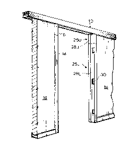
Figure 1 shows a door jamb in accord with the
invention;
Figure 2 shows the base attachment means;
Figure 3 shows the mode of installation of the
telescoping members;
Figure 4 shows the base attachment;
Figure 5 shows attachments to the telescoping
members;
Figure 6 shows a side view of the telescoping
members;
Figure 7 shows the ceiling channel support;

1316762
Figure 8 shows a side view partially in section
between the telescoping member and the ceiling
channel;
Figure 9 shows an alternate arrangement with the
ceiling channel;
Figure 10 shows the connection to the components
of Figure 9; and
Figure 11 shows an alternative door connection
using a transom,
Figure 12 shows the method of attaching the transom,
and
Figure 13 shows a detail of construction of the
upper telescopic member.
In the drawings 10 shows a ceiling channel of the types
used in my aforesaid patent with one modification as hereinafter
discussed. Such ceiling channel 10 may be attached to the
ceiling by a number of conventional means including the T - bar
shown in Fiqure 3 where T - bar is shown extending transverse
to the channel 10. (In Figure 7 a channel 10 is shown with added
upstanding spine 11 for attachment to the solid ceiling deck
by wire 15. Since the invention involves upward bias on
ceiling channel 10 there is therefore provided a compression
member 17 schematically shown between the channel 10 and the
ceiling deck to prevent upward movement of the channel 10.
This version carries side f langes 13 to carry the ceiling
panels.) Figure 3 and the remaining figures show a channel
10 without side flanges since in the main version, as shown in
Figure 7 the T - bar will commonly be suspended by a wire (not
shown) but similar to wire 15 and will bear on a compression
member (not shown) but similar to compression member 17.
The channel 10 comprises top wall 14 and vertical side walls
12 in rectilinear array defining a downwardly opening channel.
It will be understood that the ceiling channel 10 conforms
generally to the location of the intended plane of the closed
door.
--2--

1 31 6762
The door jambs of the invention comprise lower
outer and upper inner slidably telescoping channel members
16 and 18 designed to be vertically disposed. ~ach telescop-
ing channel member preferably defines in horizontal section a
general rectilinear shape open away from the intended door
opening to receive a wall or glazing panel 19. Similar parts
on the upper and lower telescoping members bear the same numeral
and suffix L or U respectively. The walls 20L, and 22L, 20U
and 22U, extend parallel to the plane of the opening and at
lo their free ends in inwardly directed lips 24L or U for connection
to a wall or glazing unit, by any conventional means.
The wall 25U, 25L of each of the telescoping channel
members facing the opening is shaped andstepped to form an
inwardly extending shoulder 28U, 28L -facing the closing
direction of the door so that the channels in section are
mirror images of each other, with the exception of hinge plate
depressions 30 on one lower member 16 and cut outs at 33 on the
corresponding location in the upper member 18. Thus the
depressions 30 receive attached hinge plates and the cut outs
33 allow the upper telescoping member to partially overlap
with the lower and slide past the hinge plate depressions.
The shoulders 28L on the lower channel 16 opposite the
hinge plates will then supply shoulder 28L to form the stop
for the door when moving toward closing position. Thus the
channel wall facing its counter part holding the hinge may
be apertured to receive the door hardware to maintain the
door closed or to lock it.
The upper and lower telescoping channel will have
their overlap adjusted to fit the floor to ceiling height
at the intended door location, and holes may be drilled and
bolts inserted to fix the overlap once the correct telescopic
overlap has been developed. However this is found unnecessary
practice in view of the fact that the upper telescopic member
13 is anchored to the ceiling and the lower telescopic member
is secured to the floor both as hereinafter described.
--3--

1 3 1 6 7 ., !
At the upper end of each upper channel 24U a
connector plate 34 extends upwardly from the upper end of
the upper channel member. The plate 34 is designed so that,
in use, i-ts plane is perpendicular to the plane of the door
opening and to a closed door. The plate 34 is shaped so that
its edges slidably meet the inner sides of the vertical
walls 12 of the ceiling channel. Thus slots 36 are cut in
opposed edges of the plate to slidably receive the inwardly
directed lips 38 of the ceiling channel. The plate 34 is a
part of the upper telescoping channel member.
At the upper end of the plate a tab 40 is bent to
be horizontal when the channels are upright. The tab is
apertured at 42 so that the upper end of the upper channel
can be fastened to the ceiling or ceiling channel to prevent
the movement of the upper end of the telescoping channel in
any horizontal directions.
The ceiling channel is provided with a small inner
channel formed by facing L shaped members 44 depending from
the upper wall member between the side walls and having the
ends of the L shaped members directed toward one another. The
small inner channel is designed to act as an upper retainer
for coil springs 46. In position over a wall panel, the coil
springs 46 act to press a plate down on the panel and which
panel is pressed downwardly against its lower limiting means
while the ceiling channel is pressed upwardly against the
ceiling. The inner channel allows the coil spring to be
held in place between members 44 and the top wall with a
helix turn between the lips of the inner channel. Similarly
in the E~rtion of the ceiling channel extending over the door
frame, and between the upper ends of the telescoping channel
coil springs 46 are installed to press downwardly on plate 50
in the alternative where a transom is used. Where a transom 52
is used it is usually of the width of the telescoping member
exclusive of the shoulder forming portion it is installed as
shown in Figure 12 to cover the space between the ceiling

1316762
channel 10 and the door. L~teral attachment of the hollow
metal transom member therefore is preferably by self-threading
bolts 58 inserted in the telescoping member through holes
drilled therein and in the side walls of the transom members.
The lower face of the transom member is preferably
stepped to form a stop - shoulder 54 for the closing or closed
door which forms a horizontal extension of the similar stop
shoulders 28U on the telescoping channel. The upper wall 56 of
the transom is shaped to provide a lower step 57 nearer the door
opening side and a high step over the remainder of the panel
thickness. The lower step is designed to underlie the adjacent
ceiling channel lip 38 and the 'riser' 60 to the higher step
meets the edge of such lip. The ceiling channel plate 50 is
shaped to have flat member 62 designed to contact the upper level
of the transom and to extend to the ceiling channel vertical wall
in the door opening direction. On the opposite side of the
transom the top plate is stepped down so that its other end
64 bears on the adjacent lip 38 of the ceiling channel and has
an up-turned end 62 to slide on the adjacent vertical wall of
the ceiling channel.
If no transom is used, so that the door top, when
closed comes immediately below the ceiling channel, the ceiling
channel may be closed by a flat plate 63 of the type used over
a wall panel and biased down by springs 46 against the lip 38 of
the ceiling channel; or by the stepped plate 50 also biased
downwardly by the spring and having a shoulder 67 defining the
closing limit of door 69 movement.
The bottom plate 68 is shaped to provide a portion 70
to be slidably received within the lower end of the lower tele-
scoping channel and is thus provided with inwardly directed slot72 designed to receive the lips 24L of the lower telescoping
member.
Apertures 74 are provided to allow the bottom plate
68 to be fixed to the floor. The purpose of the bottom plate
is to fix the lower -telescoping channel 18 against lateral
movement when the latter is slid thereover. The bottom plate
68 may be made as thick as desired for this purpose. The
channel 18 is fixed against lateral movement by being slid

1 3 1 6762
vertically over the bottom plate portion 70 and removed by
movement upwardly therefrom, taking advantage of the telescopic
adjustments be~ween telescoping channels 16 and 18.
Thus the door frame assembly is firmly ~ixed in
place as follows. Each set of telescoping channel members 16 and 18
may be somewhat contracted and the two members turned (see
Figure 3) so that the upper plate 34 is inserted between the
lips 38 of the ceiling channel received in the slots 36 of the
plate. The tab 40 rests below the inner channel on the
ceiling member and is (with the upper and lower telescoping
member) fixed against lateral movement, by being attached to the
ceiling channel with a screw 73 through aperture 42. The lower
end of the lower telescoping channel is slid over the bottom
plate portion 70. It will be seen that the door frame members
are now firmly fixed in place. Between the locations of the
telescoping members the coil springs 46 are fixed in place in the
ceiling channel and the plate 50 on the one hand or plate 63 on
the other hand (depending on whether a transom is used or not)
is fixed in place for downward bias by the springs 46, the plate
being tilted for insertion above the lips and pressed into position
against the pressure of the coil springs.
If a transom is used it is then installed by drilled
holes and self tapping bolts as described.
Any necessary door hardware or striker plate openings
77 are then provided on the lower telescoping member opposite the
hinge side of the door. As previously described, the hinge side
lower telescopic member is provided with depressions 30 for hinge
plates attached to these locations.
When it is desired to remove the door or to move
the whole wall the above procedure rnay be reversed.
In the embodiment shown, the tab 40 on the upper
plate is dimensioned to be used below and note between the L-shaped
members 44 of the small inner channel on the ceiling channel.
However, if desired, the tab 40 and its attachment may
be dimension~ ;o that it may be inserted between the lips

131676~
44 of the small channel when the channel is turned sideways to
place its upper plate 34 inside the ceiling channel and tab 40
and its connection would then be dimensioned so that when the
plate is turned to be perpendicular to the ceiling channel the
lips 44 of the small channel are received in a clearance be-
tween the tab and the upper plate. With the tab thus in place
the screw 73 may be inserted throuyh aperture 42 to fix the
telescoping members against lateral movement. As shown in
figure 5 and 8 the ceiling channel may be drilled at 79 to
allow passage of screw 73 if desired.

Representative Drawing
A single figure which represents the drawing illustrating the invention.
Administrative Status

2024-08-01:As part of the Next Generation Patents (NGP) transition, the Canadian Patents Database (CPD) now contains a more detailed Event History, which replicates the Event Log of our new back-office solution.

Please note that "Inactive:" events refers to events no longer in use in our new back-office solution.

For a clearer understanding of the status of the application/patent presented on this page, the site Disclaimer , as well as the definitions for Patent , Event History , Maintenance Fee  and Payment History  should be consulted.

Event History

Description Date
Inactive: IPC from MCD 2006-03-11
Time Limit for Reversal Expired 2005-04-27
Inactive: Adhoc Request Documented 2004-07-07
Letter Sent 2004-04-27
Inactive: CPC assigned 2003-04-25
Inactive: Adhoc Request Documented 1998-04-27
Inactive: Office letter 1998-03-11
Letter Sent 1997-04-28
Grant by Issuance 1993-04-27

Abandonment History

There is no abandonment history.

Fee History

Fee Type Anniversary Year Due Date Paid Date
MF (category 1, 5th anniv.) - small 1998-04-27 1998-02-27
MF (category 1, 6th anniv.) - small 1999-04-27 1999-04-22
MF (category 1, 7th anniv.) - small 2000-04-27 2000-03-13
MF (category 1, 8th anniv.) - small 2001-04-27 2001-02-12
MF (category 1, 9th anniv.) - small 2002-04-29 2002-04-03
MF (category 1, 10th anniv.) - small 2003-04-28 2003-02-13
Owners on Record

Note: Records showing the ownership history in alphabetical order.

Current Owners on Record
OTTO GASTEIGER
Past Owners on Record
None
Past Owners that do not appear in the "Owners on Record" listing will appear in other documentation within the application.
Documents

To view selected files, please enter reCAPTCHA code :


To view images, click a link in the Document Description column. To download the documents, select one or more checkboxes in the first column and then click the "Download Selected in PDF format (Zip Archive)" or the "Download Selected as Single PDF" button.

List of published and non-published patent-specific documents on the CPD .

If you have any difficulty accessing content, you can call the Client Service Centre at 1-866-997-1936 or send them an e-mail at CIPO Client Service Centre.


Document
Description 
Date
(yyyy-mm-dd) 
Number of pages   Size of Image (KB) 
Drawings 1993-11-11 6 137
Claims 1993-11-11 4 133
Abstract 1993-11-11 1 14
Cover Page 1993-11-11 1 11
Descriptions 1993-11-11 7 260
Representative drawing 2002-02-15 1 10
Maintenance Fee Notice 2004-06-22 1 173
Fees 2003-02-13 1 34
Fees 2001-02-12 1 30
Fees 2002-04-03 1 30
Fees 1999-04-22 1 26
Fees 2000-03-13 1 26
Correspondence 2004-07-12 4 195
Fees 1998-03-23 2 54
Fees 1998-02-27 1 31
Fees 1996-04-16 1 35
Fees 1997-04-08 1 35
Correspondence 1998-03-11 1 19
Correspondence 1996-05-22 1 32
Fees 1995-02-28 1 36
Correspondence 1993-01-29 1 22
Correspondence 1993-01-13 3 106
Correspondence 1989-05-10 1 39