Note: Descriptions are shown in the official language in which they were submitted.
~\
Page 1
NUMBER SELECTOR AND MAR~R FOR LOTTERY CARD
Field of the Invention
This invention relates generally to devices usable for
selecting numbers or groups of numbersl as well as to marking
devices generally, and more specifically, this invention relates
to a hand held device enabling numbers to be randomly selected
and a lottery ticket to be readily marked to reflect the
selection.
Background of the Invention
; A number of states of the ~nited States, as well as
countries such as Canada, have decided to solve their financial
and budgetary problems by conducting lotteries, involving in
..... ;.. ~ . .
most instances tickets, cards or play slips to be marked by the
purchaser. Lottery ticket buyers that buy a single lottery
ticket, or a number of such tickets, are faced with the problem
of selecting the numbers to be played, and then marking the
lottery ticket to refl~ect an~accurate version of the selected
numbers.
,
The purchaser paying money into the state is of course
hoping that by entering numbers on the purchased ticket that are
~ eventually selected as a winner, he or she will regain
,~
NUMB~R SELECTOR & MARÆ R ~ Page 2
substantially more money than he or she paid in. The state,
however, is careful to minimi~e the fact that the odds against a
given person winning any substantial amount o~ money in a
lottery are several million to one.
Notwithstanding the fact of the enormous odds against
winning, the population flocks to the ~rocery store, the service
station, the all-night liquor store, the drug store, and every
other conceivable kind of merchandising operation wherein
lottery sales have become a major source of activity. As the
frantic lottery ticket purchaser grasps his ticket to instant
wealth, he is confronted with a real dilemma - how to select the
numbers to be played, and how to mark the ticket or tickets in
order to accurately reElect the selected numbers.
The present invention solves these problems and frees the
ticket purchaser from the uncertainty of which numbers to play,
and provides a simple, low cost, efficient and eEfective means
~or marking the ticket immediately after such number selection.
'~'
Summary of the Invention
~ he present invention comprises a plurality of embodiments
of hand heLd number selector and lottery ticket markers o~
unique and low cost construction, that greatly assist the player
by selecting the numbers to be played, and then accurately
marking the lottery card, ticket or play slip in a rapid and
accurate manner.
For convenience and consistency oi description, the card or
play slip actually marked by the player or customer will herein
be called the lottery card. As is known, after being marked,
the lottery card typically is inserted, usually by the store
employee, into a card reader that is an essential part oE the
computer or number processor into which the selected numbers are
NI~BER SEL0CTOR ~ M~R~.R Page 3
inserted. As a result of inserting the lottery card into the
card reader, the computer or number processor then delivers a
ticket having printed thereon, numbers corresponding to the
numbers marked on the lottery card by the player. The player
must be careful to safeguard such ticket, for it may represent
the winning numbers, and it is incumbent upon the lucky player
to produce the ticket containing the winning numbers if he or
she expects to be able to claim the prize.
Some people deciding to play the lottery have the numbers
to be played already selected, so he or she need only pick up a
lottery card or play slip, and proceed to darken boxes oE the
game grids or panels of the card or play slip by the use oE a
dark pencil or ball point pen, in order to actually select the
numbers he or she is to play.
Other people, however, arrive at the store or market with
only the thought in mind of investing a certain amount oE money
in the lottery, be it $5.00, $10.00, $50.00 or whatever, and
only upoa arriving at the scene do they endeavor to select which
groups of numbers to play. After selecting the numbers, the
purchaser then has the problem oE accùrately marking the card,
so that upon being inserted into the card reader oE the
computer, he or she can rea ~ nably anticipate the delivery of a
ticket that has been imprinted with the number he or she has
selected by the use oE-the lottery card.
Accordingly, it is one of the main purposes of this
invention to help the purchaser decide which numbers to play,
and upon the numbers being selected, to assist the purchaser in
the accurate and speedy marking of the lottery card.
As will be seen in more detail hereinafter, a first
embodiment of a number selector and card marker in accordance
with this invention usable in connection with the marking oE a
card or play slip comprises a housing having substantially flat,
NUM~ER SEL~TOR & MAR~R ~ 3 ~ Page 4
generally rectangular upper and lower housing members. A slot
or aperture is formed between at least a portion of the upper
and lower housing members, into which slot the lottery card,
play slip or the like marked by the player can be inserted. The
upper housing member has a perEorate plate containing series of
closely spaced, carefully aligned holes oE an equal si~e
therein. These holes are in a rectangular array, and disposed
in columns and rows. Importantly, the placement of the
perforate plate with its series of holes must carefully coincide
with the locations of the boxes to be found in the game grids or
panels of the lottery card to be marked.
A plurality of enclosures, such as transparent enclosures,
are disposed on the upper housing member o~ this ~irst
embodiment, which serves to enclose the series o~ holes, and to
contain a plurality of small, equal size spheres, which are
captive in each enclosure. Each of these spheres is slightly
larger than the holes, so as not to be able to pass
therethrough. The size relationship of the spheres to the holes
is such that a small portion of each sphere extends below the
hole in which it resides when the spheres have come to rest in
respective holes of the perforate plate.
A marking member is located between the upper and lower
housing members, and directly below the series oE holes. A slot
is formed between the marking member and the lower housing
member for receiving the lottery card to be marked, and means
are slidably disposed in the enclosure for applying pressure to
the spheres when they have been received in respective holes of
the series of holes in the perforate plate. The pressure
applied to the spheres manifests itself through the marking
member to such an exten-t as to bring about a marking of the
cardl such that it may thereafter be read, with such marking of
the card being in respective boxes of the game grids of the
N[JMBER 5ELECTOR & MAR~R ~ 3 ~ Page 5
card. Thus, a set oE marks accurately representing the selected
sphere array is created on the panels or game grids of the
lottery card. A card marked by my device is man readable as
well as machine readable.
I am not to be limited to a number selector and lottery
card marking device having ~ive or so enclosures, each
containing it own series of balls or spheres, for in accordance
with another embodiment o~ my invention, I may utilize a single
chamber or enclosure in which spheres are trapped, and I may
utilize a perforate plate in which only one set of carefully
aligned holes are contained. In the case of the Florida Lotto
Card, there i 9 only one set oE 9~ holes accurately arranged in
columns and rows of this secondary embodiment.
When a number selector and marking device in accordance
with this invention contains only a single set oE 49 or so
holes, it i 9 obviously necessary for the player to move the
lottery card in a very accurate manner to successive new
positions with respect to the per~orate plate utilized in the
lower part o~ the device, in order that all the game grids can
be marked. To that end, I provide a plurality of alignment
devices or marks that the player can utili~e at such time as he
or she i 5 moYi ng the lottery card in order to bring about the
marking of the next panel or game grid of the card.
It is therefore a primary object of my invention to provide
a number selector and card marker packaged in one convenient,
low cost and easily utilized device.
It is another object of this invention to provide a number
selector making it conveniently possible for a lottery player to
rapidly select numbers to be played, and thereafter to achieve a
prompt and accurate marking of the!lottery card to reflect such
number selection.
NU~9EIER SELECTOR & MARÆR ~ 3 ~ Page 6
It is still another object oE this invention to provide a
number selector and card marker in which separate chambers are
utilized on a handheld device, in each of which chambers are a
number of small balls or spheres which, when the device is
shaken, can on a random basis find a hole in which to reside,
with the placement oE the ball~ or spheres thereaEter being
readily and accurately transferred onto the lottery card.
It is yet another object of my invention to provide a low
cost, highly effective, easily operated device Eor solving the
problem of a lottery player, of which numbers to select.
These and other objects, features and advantages oE my
invention will be more apparent from a study of the enclosed
drawings and the following description.
Brief Description of Drawings
Figure 1 is a perspective view of a first embodiment of a
number selector and card marker device in accordance with this
invention, with part oE this device being broken away to reveal
internal construction;
Pigure la is a sectionalized view to a somewhat larger
scale revealing preferred construction of the means by which a
given pushbutton can accomplish a sufEiciently dark marking oE
the inserted lottery card;
Figure 2 is a top view of the first embodiment in
accordance with this invention, with different portions of the
device removed so as to reveal the construction utilized at
different levels or layers of this embodiment of my device,
including balls or spheres residing in certain of the holes of
the perforate plate;
Figure 3 is a view of my device as it is held in a
playerls hand at the time the balls or spheres are being shaken;
NU~ER ~LECTOR & MARÆI~ Page 7
Figure 4 is a cross-sectional view of a portion of the
first embodiment, prepared to a larger scale, with selected
portions cut away to reveal internal construction;
Figure 5 is a fragmentary perspective view revealing the
slot in the housing, into which the ~ottery card is to be
inserted;
Figure 6 i~ a perspective view of a less expensive
embodiment of my invention, involving a marking device having
provision for marking only a single panel or game grid of a
lottery card at a time;
; Figure 6a is an enlarged cross-sectional view, revealing
how the lower part of a typical ball or sphere residing in a
hole in the perforate plate protrudes below the layer boundary
of the perforate plate, so as to be Ln a posLtLon to mark the
rectangle of a lottery card;
: : Pigure 6b is a top view of a typical perforate plate of the
: ~ type having circular holes, disposed in an array corresponding
: to a sLngle panel or game grLd of a lottery card;
Fig~re 7a is an end view of the embodiment of my invention
.depicted in Figure 6, revealing a lottery card inserted into the
card-receiving ~lot;
Figure 7b is a cross-sectional view closely relatable to
Figure 7a, and revealing internal construction;
; Figure 8a LS a fragmentary view of a typLcal section of a
: lottery card, revealing the grid pattern thereon;
Fig~e 8b is a fragmentary view of a portion of the hole
: pattern in a perforate plate having rectangularly shaped holes
rather than circular holes, with the size relationship of a
typical ball or sphere being revealed;
: Pigure 8c is a perspective view of the rectangular hole
array of Figure 8b;
,
. '
NUMBE~ ~L~TOR ~ MARÆ R Page ~
~ 3 ~
Figure 8d is a plan view of a typical perforate plate
utilizing rectangularly shaped holes;
~ igure 9 is a perspective view from a similar angle to
that depicted in E`igure 6, with Figure 9 revealing an embodiment
in which the marking member is mounted on a device that is
removable for the purpose of replacement;
Figure 10 is a si de view of the device of Figure 9,
revealing the marking member in place, and showing the slot ~or
the lottery card that is disposed immediately below the marking
member;
Figure ll is a view taken oE the top of a housing member in
accordance with a low cost embodiment of my invention, revealing
in this instance how a plurality oE notches or sightLng marks in
the edges of the housi.ng member can be used to line up with
certain numbers on the lottery card, with the alignment o~ those
certain numbers with the notches or marks assuring that all the
numbers on the panels of each card will coincide with the holes
in the perforate plate;
~ igure 12 is a perspective view of a typical card carrier
utilized in accordance with another embodiment oE this
invention, with the card carrier having a plurality of shallow,
carefully placed holes located along its long edges, to assure
the proper positioning of the card carrier with respect to the
holes in the perforate plate;
~ igure 13 is an edge view of the card carrier residing in
the housing, with part of the housing being broken away to
reveal the use therein of a spring mounted pin or plunger member
that will enter one oE the holes in the card carrier each time
one of the panel~ has been properly aligned with the perforate
plate in the housing; and
Figure 14 is a top view of another type of card carrier,
this one utilizing rounded notches disposed at spaced locations
~ '
.
'
N~MBER ~L~CTOR & MAR~3R ~ 3 ~ Page 9
along a side edge of the card carrier, into which notches a
spring biased plunger or detent member can enter in order to
assure alignment of the panels of the card with the holes in the
perforate plate of the housing.
Detailed Description
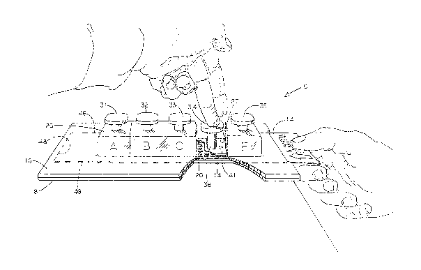
With initial reference to Figure 1, it will be seen that I
have there shown first embodiment of a number selector and card
marker device 10 in accordance with this invention. Into a slot
12 of this device, a considerable portion of a lottery card 14
is being inserted. The lottery card will reside generally in
the plane of the number selector and card marker.
The card marker 10 is principally constituted by upper and
lower housing members 16 and 1~ secured together in the manner
best seen in Figure 4. The flanges of the upper and lower
housing members may be secured together by any of a number oE
suitable means~ such as by gluing or sonic welding in case the
components are made oE plastic, or by rivets, screws, or other
fasteners in the event the members are of light metal or another
suitable material.
The upper housing member 16 of this embodiment, which is
preferably of plastic, has formed therein a perforate plate 20
in which are disposed a series 21 of carefully placed holes 22,
as will be seen in the two left panels of Figure 2. These holes
22 are of unieorm size, and are in a highly accurate rectangular
array, disposed in what may be regarded as columns and rows in
the perforate plate 20. The perforate plate 20 is typically
injection molded, utilizing a stable molded compound, such as a
polycarbonate, glass filled nylon, or PVC.
Disposed atop the series 21 of holes of this embodiment are
a group of five chambers, designated as chambers A through E in
NUM~ER SEL~CrOR & MARKER Page 10
Figure 1. Directly below each oE these charnbers are 49 holes,
laid out in five columns and ten rows in the perforate plate ~0.
The 50th hole in each chamber may or may not be formed, for the
Lotto Play Slip or lottery card utilized in Florida only has 49
boxes in each panel. Thus, for a device to be used in Florida,
the 50th hole is not formed in each part of the perforate plate.
A number of small balls or spheres 24, preferably in the nature
oE small steel shot or other hard material, are contained in
each chamber, and in Florida, six spheres are used. The balls
or spheres I use are quite close to being perEectly spherical,
and instead of steel, may be made of a hard plastic, such as
LEX~/IJ ~
nylon,~ or the like. The ~nner in which the lower surface
of a typical ball or sphere protrudes below the perforate plate,
so as to be able to mark a card disposed below the perforate
plate, is revealed in Figure 6a.
The Florida Lotto Play Slip has five panels, designated as
Panels A through E, with the 49 holes in the perforate plate of
each chamber A through E carefully corresponding to the
locations of the boxes in the several related panels or game
grids located on the Lotto Play Slip.
Quite obviously, my invention is not limited to devices
utilizing a perEorate plate having a certain number of holes, or
to holes that are circular, for the broad principles of my
device are applicaple to the marking of a large number of
different types oE cards, tickets, play slips and the like, as
may be used in other states, in Canada, in the countries of
Europe, or the like. In Canada, for example, the lottery card
has six panels or game grids.
I preferably utilize a top plate 26 forming the covering
for all five chambers A through E, with it to be understood that
a plurality of vertically disposed divider members ~7 are
utili~ed therewith, which extend downwardly from the top plate
~ ~r~ M~
NUMUER SÆLECTOR & M.9RKER ~ ' Page 11
26 so as to subdivide the chamber array into five separate
chambers of substantially equal size. The top plate is
preferably transparent, but this is not an absolute requirement.
One divider member 27 is visible in Figure 1, and two divider
members are to be seen in Figure la. Because o~ the divider
members, the six or so balls or spheres intended to be used in
each chamber are captive in those respective chambers, and
cannot move from one chamber to an adjacent one.
The holes 22 are each slightly smaller than the balls or
spheres 24, such that the balls cannot pass through the holes.
The holes are only slightly smaller than the balls, however, and
the top edges oE the holes are "broken" or countersunk to a
degree suEficient to permit a portion oE each ball to actually
extend to some degree below the bottom boundary of the upper
housing member 16. Note Figure la in this regard, where it is
apparent that the lower sphere portions are in effective contact
with the marking member 30, discussed hereinafter. As
previously mentioned, in Figure 6a I reveal an enlarged showing
in which the sidewalls of the hole are tapered to permit deep
penetration of the ball or sphere.
As should be readily apparent, by the user grasping the
embodiment of this invention represented by device 10, and
shaking same in the manner shown in Figure 3, each of the six or
so ball 8 or spheres in each chamber can each be caused, when the
device has been returned to essentially a horizontal attitude,
to randomly enter one of the holes 22 of the perEorate plate of
its respective chamber. Thus it can be seen that one oE the
goals oE my invention has been Eulfilled, that is, the ready
selection of the numbers to be played with respect to each panel
or game grid of the lottery card or play slip.
The other goal, of actually marking the card, is Eurthered
by the use of the pushbutton devices 31, 32, 33, 34 and 35 that,
NUMBER SELECTOR ~ MAR~ ~ 3 ~ Page 12
as seen in Figures 1 and 3, are respectively associated with
chambers A through ~. I may also choose to call the pushbutton
devices 31 through 35 marking devices or pressure applying
member 9 .
With reference now to Figure 4, it can be seen that the
portion of the pushbutton device or marking device 31 actually
contacted b~ the finger or fingers of the player is supported by
a pair of short shafts 36 of equal length, which extend down
through appropriately placed holes 38 formed in the top plate 26
covering the series of chambers. Inasmuch as the chambers A
through E of this ~irst emboctiment are substantially iE not
precisely identical, and each use substantially identical iE not
precisely identical components, my invention, for convenience,
is being described in some instances with regard only to a
single chamber.
The bottom ends o the short shafts 36 are secured to a
ball-contacting member 41 that is Elat and rectangular in shape,
and only slightly smaller than the chamber in which it is
operatively disposed. A compression spring 42 is utilized
between the top plate 26 and the underside of each pushbutton
device of the five chambers, which of course are pushbutton
devices 31 through 35. These springs serve to keep the
respective pushbuttons biased to their uppermost positions, and
the top side of the ball contacting member 41 disposed in
contact with the underside oE the top plate member 26. To
prevent dislodgment or misalignment oE the spring 42, I may
utilize a slight protuberance 43 on the underside of the
finger-contacting portion of each pushbutton or pressure
applying deYice 31, and a protuberance 44 in alignment tnerewith
on the upper surface of the top plate member 26, with which the
compression spring 42 interacts.
Nl~MBER SELECTOR 6 MAR~R ~ 3 ~ Page 13
Because each t~all-contacting or sphere-contacting member 41
is only slightly smaller than the chamber in which it is
vertically movable, it can be expected to contact the tops of
all six balls substantially simultaneously when the balls or
spheres have each randomly come to rest in respective holes of
the perforate plate located within the confines o~ that chamber.
Therefore, after causing the balls to seek holes and repose
therein, the player can press down on the pushbutton device 31,
32, or whichever, in order to cause the respective marking
device or baLl contacting member 41 to press down hard on all
5iX balls or spheres of that chamber at substantially the same
instant.
As also visible in Figure 9, as well as in Fiyure 2, 1
dispose a marking member 30 just below the upper housing member
16, closely adjacent the underside of the series of holes 21 of
perforate plate 20. This marking member 30 can be in the nature
of a single piece of carbon paper, or it can be of cloth or
plastic that has been impregnated with black ink. The marking
member 30 is disposed just above the slot 12 into which the
player is to insert the Lotto card 14; note Figure la. I may
utili~e a mar~ing member 30 that is a permanent part of the
device 10, or the marking member 30 can be of a slide in - slide
out nature that reposes just under the series of holes 21 of the
perEorate plate 20. This latter detail will be discussed
shortly.
Presuming the player has correctly inserted the card or
Lotto Play Slip into the slot 12 provided in accordance with the
first embodiment of this invention, panel A of the card or Lotto
Play Slip should coincide with the series of holes of chamber A,
panel B of the play slip should coincide with the series of
NUMBER SELECTOR & MARÆK ~ Page 14
holes of chamber B, and so forth, including panel E coinciding
with the location of the series oE holes of chamber E.
To assure correct alignment of the lottery card or play
slip 14 in a left-right sense, I prefer to use side members 4
on the lower housing members of this first embodiment, which
side members are only very slightly further apart than the width
of the card, ticket or play slip. These side members 46 are in
direct contact with the underside oE the edges of the upper
housi ng member . Obviously I could use another arrangement for
establishing the distance the upper member 16 is spaced Erom the
lower member 1 8, but the use of the side members 46 is
convenient, and at the same time assures proper card alignment
i n a lef t-r ig ht se nse .
Likewise, I provide a member 48 on the innermost edge of
the lower hous i ng member 18 to limit the entry oE the lottery
card or play slip. This inner member or stop serves to prevent
the player inserting the lottery card 14 too far into the first
embodiment of my device which, of course, would cause the ball
imprint not to coincide with the placement of the boxes in the
various panels or game grids of the lottery card or play slip.
The placement of member ~8 is indicated in Figure 1.
In Florida the Lotto Play Slip is 3 1/4 inch wide and 8 1/2
inch long, but obviously my number selector and card marker 10
is not to be limited to receiving play slips or cards of that or
any other particular dimension.
.
It is important to realize that because of the precision
manner in which the series of holes 21 are laid out and formed
in the perforate plate 20, and the preci sion way the housi ng
members are created, the balls or spheres can be expected to
reside in the holes of the perforate plate in a manner that
coincides precisely with the corresponding positions of the
various bo~es of the game grids depicted i n each panel o f the
lottery card. As will be noted hereinafter, I may in some
instances preE-r to utilize a perforate plate wherein each hole
.
,
Nl~MBER SELECTOR ~ MARIOER Page 15
~ 3 ~ 9
of the carefully laid out series of holes is of rectangular
cross-section. I prefer the use of injection molding
techniques, and as previously mentioned, I prefer to use a very
stable plastic, such as a suitable polycarbonate, glass Eilled
nylon, or PVC in the creation of the perforate plates.
The mold I used for the creation of perEorate plates of
injection molded material was created of tool steel, hardened
and ground, with the hole locations established to an accuracy
of .0002 inches, SUCil as by the use of a computer controlled
machining center.
As should now be apparent with respect to this ~irst
embodiment, upon the player shaking the balls until they have
each randomly come to rest in a respective hole, the player can
immediately thereafter bring about the marking oE the lottery
card or play slip so that it will accurately reflect the
positions into which the six balls or spheres of each chamber
have come to rest in the 49 holes associated with each chamber.
To accomplish such marking, the user need only push down on the
pushbutton member or pressure applying device of each chamber in
order to cause the balls or spheres 24 of that chamber to push
down hard upon the marking member 30 disposed immediately above
the lottery card or game slip 14. Because of the pre-inking of
the marking member 30, the pressure transmitted through each
ball or sphere 24 brings about the conspicuous and appropriate
marking of the boxes of the card that coincide with each hole of
the perforate plate 20 of the upper housing member 16; note
Figure la. The card becomes man readable as well as machine
readable.
The portion of the lower housing member 18 directly below
the ~ard to be marked is created to form a firm and stable base,
N~MBER SELECTOR & MAR~ R Page 16
so that the card or play slip can be readily, accurateLy and
conspicuously marked by the player using the marking device to
cause the balls or spheres to press down upon respective
portions of the lottery card 14 via the marking member 30.
As previously indicated, in accordance with the Florida
Lottery, the player, if he or she wishes, need only spend the
money involved in selecting one set of numbers of a given Lotto
Play Slip, which of course means that the user need only press
down upon the first marking device or pushbutton member 31. At
the present time, it costs $1.00 to play each set of 6iX numbers
in Florida, so if the player wishes, he or she need only select
numbers for the first panel, Panel A of the card.
More likely than not, however, the player will want to play
several sets of numbers. In that event, the player should press
down, typically in sequence, as many of the pushbuttons or
marking devices as he or she wishes to, up to Eive in this first
embodiment of my invention.
It is to be realized that my novel device is not limited to
any particular configuration, nor to the use of any particular
materials. Because I use identical balls or spheres for each
chamber, and use pushbuttons or pressure applying devices~
spring~, and the like that are identical or substantially
identiaal, each embodiment of my device readily lends itself to
economical production.
The broad principles of my invention are obviously such as
to warrant this invention not being limited to five enclosures
or chambers, to six balls, or to any particular constructional
techniques, and with regard to this fact, particular reference
is now made to the embodiments of my invention depicted in
Figures 6 through 14. It will be noted in many instances that
there is a definite and obvious relationship between the
NUMBER SELECTOR ~ ~RÆ R ~ Page 17
reference number scheme of the first embodiment, and the
reference number scheme utilized in connection with Figures 6
through 14.
In Figure 6 it is to be realized that only a single
enclosure Eor balls or spheres i5 provided in the device 60, and
it is to be understood that in accordance with this embodiment,
only a single full panel or game grid can be accommodated in the
marking location of the device at any one time. From this it
should be obvious that the lotto card 64 must be moved to a new
or second location after the first group of numbers has been
played. After the second group of numbers has been played, the
card must again be moved with respect to the upper and lower
housing members oE the device 60. In other words, it is
intended that the lottery card be incrementally moved through
the device 60, with a set of 8iX or so numbers being played, at
the player's option, at each of the five or so card locations.
I am not to be limited to any particular materials in the
construction of my lottery card marking devices, but in the
interests of a reasonable pricing structure, I prefer to make
the principal portions of a suitable plastic. It is possible,
however, when it is desired to make a particularly durable card
marking device, to fabricate it out of a light metal, but such
is not preferred.
It was of course explained in connection with the
embodiment of Figures 1 through 5 that the series of holes 21 in
the perforate plate 20 of the upper housing member 16 are
carefully laid out in precise columns and rows. The positions
of the series of holes carefully correspond to the locations of
the numbered rectangles of the panels or game grids o~ the
particular lottery card that is utilized in the state or country
involved. In a like manner, the series of circular holes 71 in
NUMBER SELECTOR & MARÆR ~ Page 18
the perforate plate 70 of Figure 6b, and the series of
rectangular holes 91 in the perforate plate 90 of Figure 8d are
carefully laid out in order to precisely correspond with the
positioning of the game grid rectangles of the lottery cards to
be utilized therewith.
Inasmuch, therefore, as precision construction has been
used throughout my device, and the card-receiving slot or space
62 between the mid portions of the upper and lower housing
members is precisely formed, the marking of the card or play
slip by the pressure applied through the balls or spheres 74 can
be expected to very closely coincide with the placement oE the
boxes ln the game grids or panels of the lottery card or play
slip,
As previously mentioned, Figure 6a reveals to a substantial
scale how a typical hole 72 in the perforate plate 70 is
configured to permit the ball or sphere 75 to fit firmly in the
hole, with the lowermost surEace of the ball or sphere
protruding below the lower boundary oE the perforate plate 70.
As is obvious, if the perforate plate is too thin, the balls or
spheres will not be able to remain stably in the holes in which
they initially come to rest, whereas if each hole is not
configured to permit the ball settling therein to protrude below
the lower boundary oE the perforate plate, it would not be
possible for the ball to bring about an acceptable marking of
the lottery card through the use of the intervening marking
member a o .
Accordingly, I either form the holes in the general manner
and configuration shown in Figure 6a, or else I counterbore the
holes somewhat, subsequent to their being formed, so that I can
be assured that each ball or sphere will sit properly in each
hole of the perforate plate.
N~MBER SELECTO~ & MARKER P~ge 19
~ 3 ~
With reference to Figure 7a, it will there be seen that the
lottery card 64 extends through the slot 62 provided in a mid
portion of the housing member of the device G0. The slot 62
extends from side to side through the device 60, and may reside
at the location corresponding to the juncture between the upper
housing member 66 and the lower housing member 68, as revealed
in Figure 7b, but obviously I am not to be limited to this
single location.
It is important to note in Figure 7b that a given panel of
the lottery card 64 resides directly below the marking member
80, with the marking member in turn reposing directly below the
perforate plate 70. It should by now be abundantly clear that
the balls or spheres must be pressed flrmly downwardly by the
marking device or pushbutton 82 into contact with the marking
member 80 and the card 64, in order for readily discernable
marks ~o be made on the lottery card. Therefore, I prefer for
the inner portion oE the lower housing member 68 to present a
flat, sturdy surface to the particular card portion it supports
at a given moment.
In view of the fact that I preEer to manufacture the upper
and lower housing members 66 and 68 of a suitable plastic, I
typically prefer to secure the adjacent margins of the upper and
lower housing members together by sonic welding, although other
means such as glue, elongate screws, or the like could be
utilized if preferred. The securing together of the upper and
lower housing members is of course accomplished while permitting
the slot 62 to extend without interruption entirely through the
device 60.
In Figure 7b I show a cross-sectional view of the device
60, in which is visible the perforate plate 70, and the six or
so balls or spheres 7~ trapped in the enclosure 77, which balls
or spheres on occasion are caused to reside in randomly selected
holes in the perEorate plate. In this figure I deliberately
NUMBE~ SELECTOR & MARKER ~ Page 20
show a single sphere 75 that has not been properly seated, and
it is to be understood that the player should not endeavor to
cause the lotto card 64 to be marked until all of the balls or
spheres contained in the enclosure have been seated in the
round, square or rectangular holes of the perforate plate.
The marking of the lottery card 64 is accomplished by the
pushbutton or marking device 82 that is slidable in a vertical
manner in the upper housing member 66. A pair of compression
springs 92 are provided on each side of the pushbutton member
82, so that it wlll normally be biased into its upper position,
which is depicted in Figure 7b. It is to be realized that I may
utilize either a pair oE leaf springs, or a pair of coil springs
at reces~ed locations in the upper housing member on each side
of the pushbutton 82. I typlcally preEer to use lea~ springs
instead of coil springs in my devices, inasmuch as leaf springs
make it possible for such devices to have less height, or in
other words, leaf springs make a more compact design possible.
Depending on the particular design, the leaf springs might be
generally L-shaped or generally U-shaped.
As is obvious, the lower surface of the pushbutton or
pressure applying member ~2 should be flat and oE hard material,
so as to assure all of the spheres being pushed with even force
down against the marking member and the lottery card when the
user pushes down upon the upper part oE the pushbutton 8~.
It will be noted that the upper housing member 66 is
configured to have a shoulder 67 on each side of the pushbutton
a2, to keep the sprlngs 92 from forcing the pushbutton or
marking device out oE the upper housing member 66 when the user
is not pushing down on same.
: As should now be clear, the arrangement is such that after
all of the balls or spheres 74 trapped in the chamber or
..
enclosure 77 have randomly been caused to become properly seated
in certain of the holes of the perEorate plate 70, the
N~jMBER SELECTOR & MA~ R ~ Page 21
pushbutton member 82 may be firmly depressed by the player, in
order to bring about a sufEiciently dark marking oE the card 64,
accomplished by the plurality of balls or spheres 74. Again,
the card 64 i5 of course disposed in the slot 62, immediate]y
below the marking member 80.
Visible in Figure 8a is a fragmentary section oE a typical
lottery card 6~, revealing to a somewhat larger scale, the
numbers that have been printed in each of the rectangles on the
game grid or panel of the card. It should now be clear that all
of the holes created in the perforate members in accordance with
my invention must be spaced to careEully coincide with this
placement of the rectangles on the game grid or panel of each
lottery card.
With reference now to Figure 8b, it will be noted that I
have here depicted to a similar scale to that used in Figure 8a,
a fragmentary portion of a perforate member 90 in which
generally rectangularly shaped holes, rather than circular
holes, have been formed. Inasmuch as the marking member 80 is
located below the perforate plate 90 but above the lottery card
64, it will be noted in Figure 8b that the marking member 80 has
been partially removed to make the numbered rectangles on the
lottery card visible. The sphera 75 depicted in Figures 8b and
8c is of a size to protrude below the lower boundary of the
perforate member, but not to pass through any of the
rectangularly shaped holes.
In ~igure 8c I provide a perspective view of several of the
~enerally rectangularly shaped holes, and from this figure it
can be seen that these holes do not have vertical sidewalls.
Rather, the sidewalls of each rectangular hole are sloped or
angled somewhat, so that the lowermost surface of each ball or
sphere can readily protrude through the lower boundary of the
" N[~MBE~ SELECTOK & MARKER Page 22
~ 3 ~
perforate plate. It is to be understood that the ball or sphere
75 is of a size not to fall through the rectangularly shaped
hole, but nevertheless being o~ a size to extend below the
perforate plate 90 for suf~icient distance as to be able to
achieve a proper and sufficient marking of the lottery card.
In Figure 8d I reveal an ent;re perEorate plate 90 of the
type having generally rectangular (or square~ holes instead of
the circular holes illustrated in the perforate plate 70
depicted in Figure 6b.
With regard to Figure 9, the marking member 80 o~ the
device 60 may be seen to be mounted upon a slidably movable
frame 86 that is readily inserted into a suitable apeeture 87
that may for example be formed at or near the lower portion of
the upper housing melnber 66. The aperture 87 will be noted to
be on a different side of the housing member than the slot 62
into which the lottery card is received, and is above latter
slot. This is because the balls or spheres being pushed down
upon the marking member 80 cause a selected darkening oE certain
portions of the lottery card -- portions that are within the
numerous rectangles contained in each panel of the lottery card.
In a manner of speaking, the aperture 87 in the housing for
receiving the slidable frame 86 for the marking member may be
regarded as 90 away from the slot 62 in which the lottery card
is to be inserted. ~s previously mentioned, the presence oE the
flat upper surface of the lower housing member 68 immediately
below the card 64 contributes significantly insofar as making it
readily possible for the user to readily bring about a
sufEiciently dark marking of the card.
By now it should be manifestly obvious that in order for a
select number of the panels or game grids of the lottery card 6~
to be properly marked, there must be proper registration between
the single set oE g9 or so holes in the perforate plate 70 (or
90) of the device 60, and the different boxes or rectangles
:
;, . .
'
NUMBER SELECTOR & MARKER 131~ Page 23
printed in the several game grids o~ panels on the Eront side oE
the Lottery card.
With further reference to the showing o~ Figure 9, the
device 60 is understood to be oE quali~y construction, and to be
of a si~e such that only one full panel or game grid can Eit at
a time within the device 60. The support member or Erame 86 is
generally U-shaped, with the marking member 80 attached thereto
by glue, pressure sensitive adhesive, or the like. In
accordance with this embodiment, additional marking members 80
could be purchased from an oEfice supply company, in order that
the device 60 can be kept in fully operational condition at all
times. When the arms of the frame 86 are oE considerable
thickness, a wide slot 88 may be utilized in each arm. Thus,
wh~n the frame 86 is in the installed position in the housing
member, and a lottery card is inserted in slot 62, the slots 88
xeceive the lottery card at a location very close below the
marking member 80.
In Figure 10 I reveal a side elevational view of the device
depicted in Figure 9, with the marking member 80 shown in the
operational position. A handle member 84 is utilized on the end
of the support member 86, to facilitate its removal from the
upper housing member 66.
Quite obviously I am not to be limited to devices 60 that
are made of plastic of high quality, for less expensive devices
may be made in accordance with my invention, which are to be
~;~thrown away after the reproductive qualities of the marking
membe~ 80 have been exhausted, or after the device has become
unsatisfactory in any other regard.
;~ ~The desired registration in accordance with the particular
embodiment of my invention deuicted in Figures 6 and 9 through
i9 accomplished by means o~ a convenient visual alignment the
user must make between the numbered rectangles appearing on the
lottery card 6~, and suitable sighting marks or alignment marks
NUM~ER SELECTOR h MARÆ R ~ Page 24
96 through 99 that are established at several appropriate
]ocations just above the card slot 62 of the housing member 66.
These marks are best seen in Figure 11. As will be explained
shortly, the distance between the marks 96 and 97 has been
carefully established, with this distance being the same as the
distance between the marks 98 and 99.
Somewhat similarly, the distance between marks or slots 96
and 98 iq a carefully established distance, and this coincides
with the distance between marks or slots 97 and 99.
It should be clearly obvious that I may also choose to
refer to the sighting marks or alignment marks as being sighting
slots or sighting notches. The sighting marks or alignment
marks ~or slots or notches) 96 through 99 will be clearly seen
in Figure 11 to line up precisely with certain numbers appearing
on the lotter~ card 64 that has been carefully inserted into the
slot 62 of the device 60.
More particularly, it will be seen in Figure 11 that by
virtue of a particular placement of the card 6~ in the device
60, the sighting mark 96 aligns with the number 8 in the first
panel of the lottery card 64, which may be nomenclatured Panel
A, whereas the sighting mark 97 aligns with the number 43 in
this same panel of the card. At the same time, sighting mark 98
aligns with the number 8 in the third panel of the lottery card,
which may be nomenclatured Panel C, whereas the sighting mark 99
at the same time aligns with the number 43 appearing in this
third panel oE the card. It is to be understood that at this
time, Panel B of the card 64 is carefully centered in the device
60.
Thus it can be seen that I have designed the device 60 to
be of a particular width, and to be precisely con~igur~d such
that when the sighting marks 96 through 99 have been aligned
'
NUI1BER SELECTOR & MARKER Page 25
with the numbers on the card mentioned above, the player can be
assured that the holes or apertures in the per~orate plate of
the device 60 will be in careful alignment with the rectangLes
of the panel of the card that is located between the ~ nels o~
the card that are at least partially visible in Figure 11. In
other words, in the illustrated instance, the user can be
assured that the numbered rectangles of Panel B oE the card 64
are in positions carefully coinciding wi~th the apertures of the
perforate plate oE the device 60, which is of course not visible
in Figure 11.
Thus, after the player has made this careful alignment of
the card in the housing 66, he or she can then proceed to
depress the pushbutton 82 on the top of the device 60 with
sufficient downward Eorce as to bring about a discernable
marking of the rectangles of Panel B of the lottery card, with
the marking of course reflecting the randomly selected positions
of the balls or spheres 74 as they reside in the apertures or
holes of the perforate plate 70 or 90.
It should be obvious to all that this position of the card
64 was chosen so as to enable a clear explanation of the use of
all four of the sighting marks or alignment marks 96 through 99
with regard to the numbered rectangles of the inserted lottery
card. This is to say, the typical user would first bring about
the marking of Panel A, before proceeding with the marking of
Panel B and the succeeding panels of the card, but I chose to
first explain the marking of Panel B so that the positioning of
all of the alignment marks or sighting marks 96 and 97 could be
fully explained.
It should also be obvious to all that during the marking of
Panel A, only sighting marks or alignment marks 9a and 99 are
utilized, with marks 96 and 97 coinciding only with an
N~B~R SEL~T~R ~ MAR~R ~ 3 ~ g Page 26
unnumbered end portion of the lotter~ card. Similarly, durir,g
the marking of Panel E, at the opposite end of the lottery card,
only sighting marks or alignment marks 96 and 97 are utilized7
with marks or slots (or notches) 98 and 99 coinciding only with
an unnumbered portion located at the other end of the lottery
card.
After the first panel of the lottery card has been marked,
it is then obviously necessary for the player to move the card
64 to a new position in the device ~0 if he or she wishes to
play another set of numbers. As should be readily apparent,
this move~ent must be for a very precise distance iE the balls
or spheres 7~ located in the enclosure 77 are to be properly
utilized to accomplish a discernable and readable marking of the
card.
Thus the player proceeds to mark tlle second panel oE the
card, and after such has been accomplished, it is again
necessary for the player to move the card 64 so that the proper
number of rectangles located in the third panel of the lottery
c~rd can be marked. It should now be clear that by careEully
utili~ing the sighting marks or alignment notches, the user or
player can readily and reliably align each successive panel of
the lottery card by visual means.
With reference now to Figure 12, it will there be seen that
I have provided an embodiment in which no visual sighting means
are utilized in assuring a proper placement oE the lottery card
in a succession of proper positions in the device 100, such
device being depicted in Figure 13. Continuing with Figure 12,
it will there be seen that I have provided a slidable card
support means or carrier 110 to receive the lottery card. As is
obviou~, the card support or carrLer 110 is created to be of a
size and confi~uration so as to snu~ly receive the card oE the
particular state or jurisdictionj in a slight recess in the
NUMBER SELECTOR ~ MAR~OER Page 27
~31~9
central portion of the carrier. In other words, there is a
raised portion around the four sides oE the card carrier 110,
with these raised portions being positioned so that a lottery
card is tightly carried therein, without the possibility oE the
card sliding to an improper or ambiguous location in the
carrier.
Also visible in Figure 12 are a series of comparatively
shallow holes 112 disposed along one or botil of the long edges
114 and 116 of the card carrier, these holes being provided for
a purpose about to be described.
As shown in Figure 12, I provide a hole 120 adjacent each
end of the card carrier, for a purpose made clear from an
inspection of Figure 13. As is visible in latter Eigure, the
user can readily lift either end of the card away Erom contact
with the card carrier 110 merely by pushing a finger ~pwardly
through the hole. This makes it very easy for the user to
re-acquire the card after it has been suitably marked.
It is important to note in Figure 13 that I ha~e provided a
spring mounted pin or plunger 124 in the housing member of the
device 110, with the plunger having a rounded lower surface or
poiat, that can readily be caused to successively enter each of
the holes 112 evenly spaced along the length of the card carrier
110.
In other words, the pin or plunger 124 in combination with
a particular hole in the card carrier amounts to a detent
arrangement serving to assure an accurate positioning oE a
corresponding panel or game grid oE the card with respect to the
holes of the perforate plate utilized in the housing of this
embodiment of my invention. This is to say, each of the holes
112 is carefully positioned with respect to the game grids or
panels of the card to be received in the support means o~
carrier 11~, such that upon the player moving the carrier or
support means from one detent location to the next, he or she by
N~MBE~ SELECTOR ~ MAR~R Page 28
1 3 ~
feel can be assured that the numbered rectangles oE the new
panel or game grid of the card will carefully correspond with
the placement of the holes in the perEorate plate of the device
100.
In the arrangement depicted in Figure 12, either end of the
card carrier can be inserted into the slot in the member 100
designed to receive same, with the placement of the holes 112
along both lony edges of the card carrier assuring that the card
carrier will tend to stop at each proper location of the card as
will assure a proper marking thereof. On the other hand, if the
card carrier is to be configured to be able to enter the device
100 from only a single direction, the series of spaced ho~es 112
along one of the long edges can be eliminated.
It is to be realized that because the holes 112 are
typically of shallow depth, that no great force is required to
move the card carrier from one card marking position to the
next. On the other hand, the pin or plunger 124 functions with
the series of holes to provide a distinct, unmistakable
positioning oE the card carrier in proper locations with respect
to the housing, such that by feel the user or player can achieve
accurate marking of the game grids or panels oE the card.
I am not to be limited to the arrangement revealed in
Figure 12, wherein a spaced series of holes are located along
aach long side of the card carrier. I say this because as shown
in Figure 14, I may create a different sort of detent
arrangement, such as one involving a series of rounded notches
132 utilized along the outer edge or edges of the card carrier.
In such instance I utillze a spring biased member 144 in the
housing, which is designed to successively enter each notch of
the card carrier when the various panels of the card are in
proper alignment with the perforate plate of the housing.
It is therefore to be seen that with either the device
shown in Figure 12, or the device shown in Figure 14, the user
N~BER ~LECTOR & MAR~R ~ Page 29
can be assured by feel that eclCIl of the panels of a lottery card
placed in the card carrier will be properly aligned with the
holes in the perforate plate, whereby the user can readily briny
about an accurate marking of the selected rectangles appearing
on the upper surface of the lottery card.
It should now be apparent that I have provided a highly
novel number selector and card marker device in which the
housing of the device can either be of a size such that
substantially the entire card can be received at one time in the
slot, or, alternatively, the housing can be comparatively small,
such that only one complete panel or game grid of the card can
be received at one time in the slot.
In both instances, aLignment means are utilized Eor
enabling the user to move the card to successive positions of
alignment in the slot in tlle cornparatively small housing, such
successive positions of alignment involving the rectangles of
each game grid of the card being brought in turn into
coincidence with the series of spaced holes.
In the comparatively inexpensive model, the alignment means
takes the form of sighting means utilized on the comparatively
small housing, so that the user can visually align the card. As
an alternative to this, the alignment means can involve the use
of a card carrier slidably mounted in the slot in the housing.
The card carrier is adapted to receive the card to be marked in
an unambiguous location thereon, and the user by feel can quite
effectively move the card carrier to a series of distinct
positions of alignment with respect to the small housing.
It should now be clear that this invention is oE sufficient
breadth that it can take a number of different forms or
configurations, and I am not to be limited except as required by
the scope of the appended claims.