Note: Descriptions are shown in the official language in which they were submitted.
J
1~-1 .qpr ~ 13:',7
13172~9
TIrrLE
FLEXIBLE MUG HOLDER
FIELD OF THE INVENTION
The present invention relates g~nerally to a
holder for maintaining open-top liquid containers in an
upright position and more specifically to a removable cup
or mug holder for use in a vehicle.
BACKGROUND OF THE INVENTION
Various designs and configurations or open-top
liquid container holders have been used before. U.S.
Patent Nos. 1,782,962 to ~obbs; 3,269,683 to Shinaver; and
4,191,350 to Ormond, each disclose a cage-type holder
comprising vertical struts joined at their upper and lower
ends to two rings for providing wall support for the
; 15 container. The Shinaver holder has a base made from eight
fixed arms extending radially like the spokes of a wheel
from a common central portion to a corresponding vertical
strut. This cage-type holder, however, is not flexible
because of its fixed-diameter base and therefore, it
cannot be used for a wide variety of container sizes. The
Hobbs holder also has a fixed diameter base due to member
12. Similarly, the Ormond container cannot e~pand to hold
a container larger than lower ring 42.
U.S. Patent No. 1,902,608 to Baltzley et al.
disclose~ a holder for a glass having an expandable
supporting base, however, this holder is complicated and
hard to make because of its many moving parts. The
following patents show other designs and configurations
.
-2- ~3172~9
for container holders: U.S. Patent Nos. 1,778,~23;
1,9~3,225; 3,568,969; 3,814,367; 4,131,259; 4,634,0~9;
4,654,274; 4,655,425; and 4,678,154.
It would be desirable, to provide a flexibl~
holder for an open-top liquid container having a simple,
expandable base which can receive a variety of diferent
sizes of containers and which could be easily attached to
or removed from a support such as a car window.
Preferably, the holder could also accommodate containers
having a handle such as a mug.
SUMMARY OF THE INVENTION
The present invention generally relates to a
flexible holder for a container and more specifically to a
removable holder for an open-top li~uid container which
has a flexible base that can accommodate containers of
various sizes. The present invention utilizes a flexible
hinge as its base which permits the holder to expand and
contract, thereby adjusting itself to snuggly hold
containers of various sizes. Preferably, the holder has a
gap in it which can accommodate a protrusion from the
container such as a handle.
Another important advantage of the holders of
the present invention is that they can easily be stacked
since one holder nests inside of another holder due to the
flexible base and the tapered sides. This is very
important in manufacturing, distributing and displaying
the holders since a stack of holders of the present
invention does not require near the amount of storage
space that is required for holders with a fixed base.
Generally, the present invention comprises a
cylindrical, cage-type holder for a container made of a
resilient material and comprising an expandable hinge as a
~3~ ~317~69
supporting base wherein a plurality of curved arms extend
outwardly f rom a common hub at the center of the base to a
plurality of members. Preferably, the arms are 1exibl~
but they may be comprised of a flexible irst portion
connected to the hub and a rigid second portion connected
to the members.
The intersections of the arms and the members
define the periphery of the flexible hinge such that an
outwardly radial force on the members causes the 1exible
hinge to expand, thereby increasing the periphery of the
base. The members extend upwardly from the arms to a
circular ring which defines the upper periphery of the
holder, while the members form tha supporting sides and
walls thereof. Preferably, the circular ring is of a
larger diameter than the periphery of the base so that the
supporting sides are tapered and enable the holders to be
stacked easily one inside another. Also, the upper
circular ring, preferably, has a gap which can accommodate
the handle of a container such as a mug.
The holder also contains an attachment means for
removably mo~nting it to an ob;ect ~uch as a door or
window of a vehicle or car. Preferably, the attachment
means is connected to the ring at a point opposite the gap
and comprises a first flange which exkends upwardly and
then outwardly to provide clearance from the ring, a
bendable hinge attached to the first flange and a second
flange attached to the bendable hinge which extends both
upwardly and downwardly from the bendable hinge such that
the bendable hinge resiliently urges the holder toward the
door. Preferably, the first flange is L-shaped and the
second flange further comprises two spaced-apart
protruding tongs that can be inserted between two
surfaces, such as the window and door of a car, for better
stability. The bendable hinge operates such that the
protruding tongs of the second flange exert a force
-4- ~3172~
inwardly toward the first flange and holder rather than
outwardly as in other holders. This enables khe bendable
hinge to urge the holder into close engagement with the
door.
Other details, objects and advantages of the
present invention will become more readily apparent from
the following description and accompanying drawings of a
presently preferred embodiment thereof.
BRIEF DESCRIPTION OF THE DRAWINGS
In the accompanying drawings, a preferred
embodiment of the present invention is illustrated, by way
of example only, wherein:
Figure 1 is a perspective view of the holder of
the present invention;
Figure 2 is a top view of the mug holder shown
in Figure l;
Figure 3 is a bottom view of the mug holder
shown in Figure l;
Eigure 4 is a front view of the mug holder shown
in Figure l;
Figure 5 is a back view of the mug holder shown
in Figure 1.
DESCRIPTION OF THE_PREFERRED EMBODIMENT
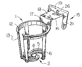
Figure 1 shows a perspective view of the
container holder 1 of the present invention utilizing the
expandable or flexible hinge 2 as the base 3 of the
holder. The flexible hinge 2 can be seen more clearly in
1~3~L72~9
Figures 2 and 3. Preferably, the base has a common hub 4
at its center with a plurality of curved arms 5 extending
outwardly therefrom. The arms 5 are attached at one end
to the hub 4 and at the other end to a plurality of
memb~rs 6 which define the periphery of base 3.
Preferably, the members 6 extend upwardly from arms 5 and
form the sides or walls of the hoLder 1.
While the embodiment shown in the Figures has
four arms 5a-5d and five members 6a-6e with one arm 5a
being connected to two members (6a, 6b~, this is not the
only possible configuration. Many other configurations
would be apparent to one skilled in the art. For example,
three or five arms could be used as long as the number of
arms 5 is sufficient to provide a base upon which to rest
the container when it is placed in holder 1. Similarly,
the number o members 6 used to form the sides of the
holder 1 may be more or less than that shown in the
drawings. Also, the width of the members 6 may vary such
that the sides of the holder 1 are more or less open.
Preferably the arms 5 are made from a resilient
material such as plastic. In fact, the entire holder 1 is
preferably made of a resilient material such as plastic~
In this way the present invention can b8 mass produced
using an injection mold and is also more durable. The
holder, however, does not have to be made entirely from a
resilient material. It could be made of material which is
rigid, provide~d certain connection points are flexible as
will be explained later.
As shown in Figures 1, 2 and 3, the hub 4,
preferabiy, is circular and the attachment points for
arms 5 are evenly spaced about the hub 4. This helps
distribute the forces evenly so that hub 4 rotates around
its center point 7 as the fl~xible hinge expands and
contracts rather than being displaced laterally.
, . ,, ~ . . .
-6- 131~2~9
Preferably, hub 4 has a plurality of projections 8 which
extend obliquely from the hub. The nur~ber of
projections 8 should equal the number of arms 5 so that
each arm 5 is connected to only one projection 8.
S In one embodiment, arms 5 have a resilient or
1exible first ~0 po~t~on and a second portion ~1 which
may be either rig~ or flexible. Preferably, the first
portion 10 is much smaller and thinner than the second
portion 11 so that it can bend as the flexible hinge 2
expands and contracts. First portion 10 is attached to a
projection 8. Second portion 11, preferably, is curved
and is connected to at least one member 6.
Members 6 extend upwardly from arms 5 and
connect with a ring 12 which defines the upper periphery
of the holder 1. Preferably, members 6 extend upwardly
and outwardly such that ring 12 is larger than the
periphery of base 3. Thus, ring 12 and members 6 define
an opening which tapers down to the smaller diameter base
formed by flexible hinge 2. This enables one holder to be
easily stacked inside another without reguiring very much
additional space. This is very important in the
manufacture, distribution and display of the holders.
Without this ability to nest inside one another, the
holders would be much more difficult to manufact-ure and
distribute because of the increased storage space required
by them.
Ring 12 may be solid or, preferably, it has a
gap 13 therein to accommodate a protrusion on a container
such as a handle. As can be seen in Figures 1 and 4, the
gap 13 along with the members 6a and 6b actually form a
slot 14 through which the handle of a container such as a
mug may protrude when it is resting on the base 3 in the
holder 1.
_7_ 1317269
Of course, the holder 1 cannot receive a
container having as its smallest diameter a diameter which
is larger 'han the diameter of ring 12 since a portion of
the container must pass through ring 12. If~ however, the
base of the container is smaller than ~ing 12, but larger
than the existing periphery of base 3, base 3 due to the
flexible hinge 2, can expand to accommodate the larger
diameter as the container is placed in the holder. As the
flexible hinge 2 expands, base 3 expands and the bottoms
of members 6 move outwardly to accommodate the base of the
container. When the container is removed, the flexible
hinge 2 contracts somewhat, attempting to return the
base 3 to its original size. The tension in flexible
hinge 2 when it expands helps hold the containPr snuggly
within members 6. This design also enables the holders to
be easily stacked, with the base of one holder sliding
into and expanding the base of another holder just as a
container would.
Holder 1 is designed to be easily attached to or
removed from a support in a vehicle. Preferably, the
support is a car window and door. An attachment means lS
connected to ring 12 is used to removably attach the
holder 1 to a car window and door. Preerably, the
attachment means 15 is connected to ring 12 directly
opposite from gap 13 and comprises an L-shaped first
flange 16 having a first portion 17 which extends upwardly
from ring 12 and a second portion 18 which extends
outwardly from the first portion 17 to provide clearance
from ring 12, a bendable hinge 24, and a second flange 19
which extends both upwardly and downwardly from the
bendable hinge 24 such that the action of bendable hinge
24 resiliently urges the holder l toward the door.
Preferably, second flange 19 includes two protruding tongs
and 21 which are located on either side of horizontal
second portion 18 and which descend and engage the inside
of the door. Locating tongs 20 and 21 in this fashion
i
-8- 13~269
provides greater stability than if they were located in
some other fashion. The tongs 20 and 21 are tapered at
ends 22 and 23 to enable them to slide easily between the
window and the door when being inserted. Bendable hinge
24 also enables tongs 20 and 21 to be inserted more
easily.
Preferably, bendable hinge 24 is formed by a
groove 25 at the connection between the hori~ontal second
portion 18 of first flange 16 and second flange 19 as
shown in Figure 3. This region should be made of a
flexible material such as plastic to permit bendable
hinge 24 to bend along groove 25 (see Figures 1 and 3).
Preferably, another groove 27 is located at the connection
between the first portion 17 and the second portion 18 o
flange 16 to form a second bendable hinge 28. This groove
also enables the flange 16 to bend if necessary when
attaching the holder 1. The second flange l9 preferably
has a hole 26 therein.
The bendable hinge 24 as well as the second
bendable hinge 28 enable attachment means 15 to compensate
for the different sizes of car doors. Present holders
typically have a rigid engagement and are extremely
difficult to insert in the window area and do nok work
well with the wide variety of car door sizes. The present
invention, however, with at least one bendable hinge in
the attachment means can be adjusted to fit almost any
door.
While a presently preferred embodiment of
practicing the invention has been shown and described with
particularity in connection with the accompanying
drawings, the invention may otherwise be embodied within
the scope of the following claims.