Note: Descriptions are shown in the official language in which they were submitted.
7~2~
CE;NTR I FtJGAL SEAL
This invention relates to sealing means for the
prevention of fluid leakage between the rotatin~ and
stationary members of centrifugal fluid pumps, turbines,
agitators and the like.
Conventionally, most centrifugal pumps prevent or
control fluid leakage, both during operation and while
stationary, by the use of interfacial seals. These seals
contain stationary and rotating sealing surfaces which
are held in sliding contact with a controlled surface
pressure to minimise fluid leakage past the sealing
surfaces. Interfacial seals may be subdivided into two
classes dependent upon the disposition of the sealing
surfaces relative to the rotating shaft axis, viz. axial
seals and radial seals. Both types of seals are widely
used in centrifugal fluid pumps.
Axial seals encompass the broad class of mechanical
end face seals in which the sealing surfaces are flat,
rigid, and disposed normally to the shaft axis. These
seals have been widely applied to centrifugal pump,
turbine and agitator shaft sealing applications with gas,
liquid and slurries as the pumped product, and have been
developed in an extensive range of variant designs.
Radial seals define the class of shaft seals in
which the sealing contact surface is cylindrical and
concentric with the pump shaft axis. The stuffing box is
a commonly used seal of this type in which impermeable
and compliant packing material is contained and
pressurised in an annular cavity surrounding the shaft by
an axially adjusted gland member. This type of seal is
extensively applied in both liquid and slurry centrifugal
pumps. Seals of this type belong to the class of radial
seals.
The abrasive nature of pumped fluid in centrifugal
slurry pumps commonly results in severe wear of shaft
seal elements resulting in increased fluid leakage and
maintenance requirements. Even with clean liquid pumps,
sealing elements wear and require adjustment. These
problems have resulted in the development of hydrodynamic
shaft seals which are incorporated in many centrifugal
~ s3 ~ r^~
-- 2
slurry pumps. These invariably comprise auxiliary
pumping vanes on the impeller which develop a
hydrodynamic fluid pressure to eliminate leakage from the
pump casing. During pump operation fluid leakage is
eliminated or substantially reduced with this type of non
contacting seal. Supplementary sealing means are
required additional to the hydrodynamic seal to prevent
leakage from the pump when stationary. Such static seals
are commonly interfacial seals of the radial type.
Although fluid leakage, in operation, is effectively
prevented or controlled by the hydrodynamic seal, the
continuous sliding contact at the static seal surfaces
results in abrasive wear at these surfaces with resultant
loss of static sealing performance.
The aim of this invention is to overcome, by novel
means, a number of limitations associated with
conventional centrifugal fluid pump seals and to improve
current sealing technology, particularly in relation to,
but not limited to, centrifugal slurry pumps (where
abrasive wear is greatest), and in accordance with the
following objectives:
(a) to increase the effective operating life of pump
seals between maintenance overhauls;
(b) to reduce abrasive wear rate at the sealing
surfaces;5 (c) to provide a seal suitable for use under the most
adverse fluid conditions, including heterogeneous
fluids typical of coarse abrasive slurries;
(d) to permit substantial axial displacement between
the stationary and rotating sealing surfaces; and0 (e) to provide a seal with automatic loading of sealing
surfaces and requiring no manual adjustment of
loading either during installation or in operation.
The present invention in one broad form comprises a
centrifugal sealing member for preventing leakage between
a rotating member and a stationary member with an outer
cylindrical surface, said sealing member comprising an
annular support member and an inner annular engaging
member, said support member being adapted to be mounted
13~7~
-- 3 --
on said rotating member, with said annular engaging
member being adapted to sealingly engage around the said
outer cylindrical surface of the stationary member when
said rotating member slows below a predetermined speed,
and is adapted to disengage from around the said outer
cylindrical surface when the rotating member rotates
faster than the predetermined speed, to provide a running
clearance between the centrifugal sealing member and the
stationary member.
Preferably seals according to embodiments of the
present invention are used for preventing fluid leakage
through the running clearance between stationary and
rotating members of centrifugal pumps and the like, which
incorporate hydrodynamic means for preventing such
leakage until their speed of rotation decreases by some
predetermined fraction of normal operating speed. The
seal comprises a stationary member with an outer
cylindrical surface substantially concentric with the
axis of rotation of the rotating members and adapted to
be engaged in sealing contact by a surrounding annular
sealing member detachably mounted on an axially adjacent
rotating member by fluid tight means. The mass and the
composite modulus of radial elasticity of the annular
sealing member is so proportioned that, at a rotational
speed greater than that at which leakage would cease to
be prevented by the said hydrodynamic means, the annular
sealing member extends radially outwards due to
centrifugal force sufficiently to provide a running
clearance between the rotating annular sealing member and
the stationary cylindrical surface.
The invention will now be described by way of
example with reference to the accompanying drawings, in
which:
Fig. 1 is a partial cross sectional view of a
preferred embodiment of the present invention with the
pump shaft stationary;
Fig. 2 illustrates another embodiment of the
present invention in partial cross section with the pump
shaft stationary; and
~ ~ ~ r~ 3 ~ ~3
Fig. 3 is partial cross sectional view taken on
line I I of Fig. 2.
Like parts are illustrated by like characters
throughout the specification and drawings.
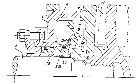
Fig. 1 shows one preferred embodiment of the
invention in a simple form as applied to a centriEugal
slurry pump. Pump impeller 1 is attached to shaft 2
which contains the pressurised fluid discharging from the
periphery of rotating impeller 1. A secondary sealing
impeller or expeller 3 is mounted on shaft 2 adjacent to
impeller 1 and contained within a separate sealing
chamber 4 formed by the external surface of casing member
5 and expeller chamber 6 which are clamped together in
sealing contact. Expeller 3 contains multiple vanes 7 of
substantially radial form attached to a substantially
plane disc rotatably driven by shaft 2 and substantially
concentric therewith. The annular sealing member 8
comprises an outer annular support member 9 and an
integral engaging member 10, made of a suitable
elastomeric material. A stiffening reinforcement ring 11
may be embedded in the sealing member. The sealing ring
8 engages in a fluid tight manner in the annular spigot
12 in the expeller 3.
The dimensions of the engaging means 10 and its
modulus of elasticity are chosen such that at rotational
speeds greater than that at which leakage would cease to
be prevented by hydrodynamic means (i.e. the rotation of
the expeller 3), the engaging means 10 moves under the
influence of the centrifugal force out of sealing
engagement with the outer cylindrical sealing surface 13,
to provide a running clearance between the rotating
sealing member 8 and the cylindrical sealing surface 13.
The main elements of the hydrodynamic sealing means
in the embodiment shown in Fig. 1 comprise the vanes 7 of
expeller 3 and auxiliary leakage vanes 14 of impeller 1
operating in concert with the adjacent surfaces of casing
5, expeller chamber 6, and stationary spoiler vanes 15.
The principal elements of the seal, formed by
utilising the sealing member of the present invention, of
,.
_ 5 _ ~3~7~f~
which one embodiment is shown in Fig . 1, comprise the
annular sealing member 8, expeller 3, and stationary
member 16.
Another embodiment of the sealing member is shown
in Figs 2 and 3. With reference to Fig. 2, the rotating
sleeve 17 is mounted on shaft 2 adjacent and in driving
contact with expeller 3. Stationary member 16 is mounted
with sealing engagement in expeller chamber 6 with its
outer cylindrical sealing surface 14 concentric with the
axis of shaft 2. The annular sealing member 8 is the
principal component of the seal, and comprises a helical
tension spring 18 disposed in toroidal form with its
rectilineal axis of symmetry colinear with the axis of
shaft 2 and enclosed by and in intimate driving contact
with an elastomeric sheath on annular engaging member 19,
separate multiple ballast weights 20 mounted with working
radial clearance within the toroidal core of spring 18,
and a helical tension spring 21 disposed in toroidal form
and moulded within an annular mounting bead of elastomer
2 concentric with shaft 2. The multiple ballast weights
20 are configured to provide maximum density of the
toroidal core of spring 18. They are typically
constructed in high density material, and in the
embodiment shown in Fig. 3 have a barrel shaped form with
conical ends, and are packed with minimum radial and end
clearance within the toroidal core of spring 18 to permit
relative movement between the spring coils and ballast
weights 20. Spring 18 contains driving means 23 to
rotatably drive ballast weights 20 with annular sealing
member 8. In the embodiment shown in Fig. 3, the driviny
means 23 is combined with a toroidal core diameter of
spring 18 and provides a rotational driving surface for
ballast weights 20. The mounting bead 22 is integral
with elastomeric sheath 19 and displaces axially from
helical tension spring 18. Mounting bead 22 engages with
static sealing contact a matching grooved recess 24 in
rotation sleeve member 17, which determines the axial and
radial location of annular sealing member 8 relative to
rotating shaft 2. Annular sealing member 8 is rotatably
7 c3 ~ ~
driven by multiple radially disposed projections 25 at
its outer periphery which are integral with elastomeric
sheath 13, and which engage with corresponding surfaces
26 of vanes 7 of e~peller 3.
At its inner radial extremity, and displaced
axially remote from mounting bead 22, annular sealing
member 8 incorporates a radial inward projection of
elastomeric sheath 19 to form a continuous sealing lip 27
of limited axial width, concentrlc with shaft 2, and
having an inner cylindrical sealing surface 28 in radial
sealing contact with outer cylindrical surface 13 of
stationary member 16. The geometry of seal lip 27 is
configured to provide for substantial radial wear without
detriment to sealing performance. Sealing lip 27 may
typically comprise a harder grade of elastomer than the
elastomeric sheath 19, to which it is integrally formed,
to provide more favourable wear characteristics. With
pump shaft 2 stationary, the outer periphery of the
annular sealing member 8 has a small radial clearance,
with the inner radial extremity 29 of vanes 7 of expeller
3.
The principal elements of the seal, formed by
utilising the sealing member of the present invention, of
which one embodiment is shown in Fig. 2, comprise the
annular sealing member 8, rotating sleeve 17, e~peller 3,
and stationary member 16.
Operation of the pump seal will be described with
reference to Figs 1, 2 and 3. Effective sealing against
fluid leakage is required for the two conditions of
stationary and rotating shaft systems. With shaft 2
stationary, and in the low speed range during pump
start-up, sealing is provided wholly by the seal of this
invention. In this condition sealing chamber 4 is
normally flooded with fluid, immersing the outer surface
of annuldr sealing member 8 between seal lip 27 and the
outer su2port member 9 ~in Fig. 1) or elastomer mounting
bead 22 (in Fig. 2). Sealing surface 13 of stationary
sleeve member 16 and annular sealing member 8 are in
sealing contact with a radial pressure predetermined to
- 7 ~ ) I J ~
e~clude fluid leakage past their common contact surfaces.
The inner surface area of annular sealing member 8
is normally exposed to the atmosphere and subject to
ambient pressure. If the outer periphery of annular
sealing mernber 8 is subjected to a fluid pressure
elevated above ambient, as may occur by supercharging of
the pump inlet, the increased fluid pressure acting upon
annular sealing member 8 causes increased contact
pressures at seal lip 27 (in Figs 1 and 2), and at
mounting bead 22 (in Fig. 2 only), thereby providing
increased resistance to fluid leakage.
At normal pump operating speed, and in the upper
speed range during pump start-up, sealing against fluid
leakage between stationary and rotating members is
lS provided wholly by hydrodynamic effects. The combination
of expeller vanes 7 and auxiliary leakage vanes 14 of
impeller 1 develops a centrifugal fluid pressure in
excess of the impeller discharge pressure, hence fluid
leakage from casing 5 via the sealing chamber 4 is
prevented. In normal seal operation an equilibrium
condition is established with fluid in sealing chamber 4
driven by expeller vanes 7 in an annular vortex at the
periphery of the chamber, surrounding inner zones of air
on both sides of expeller 3. Annular sealing member 8
occupies a fluid free region within the annular vortex,
and leakage from sealing chamber 4 across sealing faces
13 and 28 is thus prevented by hydrodynamic fluid
effects. At full operating pump speed annular sealing
member 8 is in its fully radially expanded position, with
its outer periphery in supporting contact with surfaces
29 of expeller 3 (for embodiment shown in Fig. 2), with
corresponding separation of sealing surfaces 13 and 28.
In Fig. 1, radial expansion of annular sealing lip
10 of member 8 is caused by centrifugal force acting on
the mass of the lip. This radial expansion is resisted
at low speeds by elastic circumferential tension in seal
lip 10.
In the speed range approaching normal pump
operating speeds the combined centrifugal loading
- 8 -
predominates over the combined elastic circumferential
tension, resulting in radial expansion of annular sealing
member lip 27, with a corresponding radial separation of
sealing surfaces 13 and 28. The critical rotational
speed of annular sealing member 19 at which sealing
surfaces 13 and 28 separate is an important seal design
parameter, and is a function of the axial spacing
relationship of seal lip 27, spring 18 and mounting bead
22; the masses of ballast weights 20, spring 18 and
elastomeric sheath 19; and the radial stiffness of spring
18, seal lip 10 stiffness and mass and elastomeric sheath
19. Typically these design parameters are configured to
produce separation of sealing surfaces 13 and 28 at a
rotational speed lower than the lowest limit of normal
pump operating speeds.
Sealing surfaces 13 and 28 are thus in sliding
contact only during the brief starting and stopping
process. During normal pump operation the surfaces are
separated with consequent absence of abrasive wear. This
is of particular relevance in centrifugal slurry pumps in
which sliding surfaces are unavoidably contaminated by
abrasive solid particles with resultant rapid abrasive
wear. Abrasive wear at sealing surfaces 13 and 28 is
limited only to the acceleration and deceleration periods
during starting and shut-down of the pump during which
the pump speed is below the critical seal separation
speed.
It is a common feature of centrifugal slurry pumps
that axial adjustment of shaft 2 and associated rotating
components is normally provided to improve deteriorating
pump performance resulting from increased impeller ~nd
clearances caused by abrasive wear. The present
invention can tolerate large axial displacement of seal
lip of the sealing member due to its cylindrical contact
3S geometry and axial extent of the matching stationary
sealing surface. Axial shaft adjustment is beneficial to
seal operation with this invention as the localised worn
- 9 - ~?~17~
stationary surface adjacent to the surface of annular
sealing member 16 is replaced with unworn surface by
axial adjustment of the shaft.
As will be apparent to those skilled in the art
in the light of the foregoing disclosure, many
alterations and modifications are possible in the
practice of this inven-tion without departing from the
spirit or scope thereof. Accordingly, the scope of the
invention is -to be construed in accordance with the
substance defined by the following claims.