Note: Descriptions are shown in the official language in which they were submitted.
1317358
SPEED CONTROL SYSTEM
Brief Summary of the Invention
This invention relates to control systems of the kind
adapted to control the running speed and position of a
carriage or similar device adapted to move along a
predetermined running path, for example a carriage of the type
used to transport workpieces in a manufacturing or processing
plant.
A known speed control system for a linear motor-driven
carriage or similar running body, described in Japanese laid-
open utility model application 54021/1988, comprises a slotted
plate affixed to the carriage. The plate has a plurality of
slots arranged at predetermined intervals along the direction
of movement of the carriage. A plurality of light sources and
photosensors are disposed along the path of the carriage and
opposed to each other so that the slotted plate on the
carriage moves in a path between the light sources and their
opposed photosensors to interrupt the light paths. The
outputs of the photosensors are connected in a circuit so that
they are logically ORed together to provide a single output
signal.
One drawback of the known speed control system is that
speed detection is possible only within a limited range of
carriage positions in which speed detecting means are
provided. Thus, a large number of light sources and
photosensors is required, especially in the case of a long
,~
~317358
running path. Moreover, providing a satisfactory OR circuit
is difficult because of problems in phase matching.
In the known speed control system, braking is effected
when the carriage passes a fixed predetermined position.
Thus, the ultimate stopping position of the carriage varies,
depending on carriage speed.
The present invention comprises a slotted plate arranged
along the path of the carriage rather than carried by the
carriage. The slots of the plate are disposed at
predetermined intervals in the direction of travel of the
carriage. Light emitting and light receiving devices are
arranged to provide a light path at least part of which moves
with the carriage. The moving part of the light path is
disposed so that it alternately passes through the slots in
the plate and is interrupted by the portions of the plate
between the slots as the carriage moves along its path of
movement. A transducer is provided to convert pulses from the
light-receiving devices to a signal representing the speed of
the carriage. A counter is also provided for counting the
pulses from the light-receiving devices in order to determine
the position of the carriaqe. Speed setting means is provided
to generate a set speed signal in response to the count of the
counter. Thus, the set speed signal is dependent on the
carriage position. A comparator compares the speed signal
from the transducer with the set speed signal to generate a
speed control signal for the carriage.
As the carriage moves along its predetermined path, the
light in the portion of the light path which moves with the
3 13173~8
carriage passes through the slots in the slotted plate and is
received by the light-receiving means as light pulse signals.
Corresponding electrical pulses are transmitted to the
transducer and the counter.
The transducer transforms the pulse signals to speed
signals and sends the speed signals to the comparator. The
counter counts the pulse signals and transmits the count to
the speed setting means. The speed setting means determines
the position of the carriage on the basis of the count, and
produces a set speed signal which has a predetermined value
which is a function of the carriage position. The speed
setting means transmits the set speed signal to the
comparator.
The comparator compares the set speed signal with the
speed signal. The output of the comparator is used to control
the speed of the carriage, e.g. by controlling the linear
motor driving the carriage, so that the carriage speed is
reduced if the actual speed exceeds the set speed, and the
speed of the carriage is increased if the actual speed is less
than the set speed.
The principal objects of this invention are to provide a
speed control which overcomes the aforementioned deficiencies
of the prior art, and also to provide a speed control system
in which the stopping position of the carriage is less
dependent on the carriage operating speed. It is also an
object of the invention to provide a simple and effective
means for coupling pulse signals from a moving carriage to
stationary components of the speed control system. Still a
131 7~8
further object of the invention is to provide a simple and
inexpensive speed control system for work carriagesO
Brief Descr ption of the Drawings
FIG. 1 is a schematic diagram of the speed control system
according to the invention;
FIG. 2 is a plot showing the relationship of carriage
speed and carriage stop position in a carriage transporting
system utilizing the present invention; and
FIG.3 is a similar plot showing the relationship of
carriage speed and carriage stop position in a carriage
transporting system of the prior art.
Detailed Description
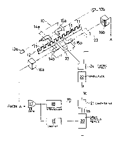
FIG. 1 shows a carriage 10 adapted to move along a
straight running path. A plate 12 extends along the path of
the carriage, preferakly along substantially its entire
length, and has a plurality of slots 11 disposed along its
length for allowing a light beam to pass from one side of the
plate to the other. These slots are preferably arranged at a
predetermined uniform pitch, although in some cases it may be
advantageous to vary the pitch of the array of slots along the
length of plate 12.
Light sources 13a and 13b, for example lasers, are
disposed at both ends of the running path, and each produces a
beam directed parallel to the running path.
Two pairs of optical conductors are provided on carriage
10, one pair comprising conductors 14a and 14b, and the other
13~7358
pair comprising conductors 15a and 15b. These optical
conductors may take the form of optical fibers or optical
fiber bundles, and are bent in order to deflect the light
beams from the light sources through the slots in plate 12 and
back to the ends of the running path. Mirrors may be used as
alternative means for light beam deflection.
Ends of light conductors 14a and 15a face light sources
13a and 13b respectively. Similarly, ends of light conductors
14b and 15b face light receiving devices 16a and 16b provided
at opposite ends of the running path. The other ends of the
light conductors of each pair 14a-14b and 15a-15b face each
other with the slotted plate 12 therebetween. Thus, two light
paths are provided. One light path extends from source 13a to
light receiver 16a, through light conductors 14a and 14b.
Similarly, the other light path extends from source 13b to
light receiver 16b through light conductors 15a and 15b. The
portion of each light path extending across the slotted plate
moves with the carriage.
The light receiving devices, which may comprise
photodiodes, phototransistors or other light-sensing devices
having a rapid response, produce an "on-off" modulated
electrical signal in response to light passing through the
slots 11 in plate 12. In other words, they receive light
pulses and convert them to electrical pulses.
OR gate 17 receives inputs from both light-receiving
devices 16a and 16b. The provision of two pairs of optical
fibers, and light sources and light-receiving devices at both
ends of the running path insures that while one set of light
6 1 31 73~8
conductors moves away from its corresponding light source and
light receiver, the other set moves closer to its
corresponding light source and light receiver. This insures
that a light pulse of adequate strength is received at least
at one end of the running path regardless of the position of
the carriage.
The output of OR gate 17 is an electrical pulse signal,
which is converted by a transducer 18 to a signal Vn
representative of the current speed of the carriage.
Counter l9 is connected to count the electrical pulses
appearing at the output of OR gate 17. The count in counter
19 is representative of the current position of the carriage.
A signal from the driving circuit for the linear carriage
driving motor causes the counter to count up or down depending
on the direction of movement of the carriage.
Speed setting means 20 produces a speed-setting signal Vs
as a function of the count in counter 19. A predetermined
functional relationship is prestored in speed setting means
20. ~he speed setting signal Vs is an output which corresponds
to the predetermined desired carriage speed for any given
carriage position.
Comparator 21 compares the current speed signal Vn from
transducer 18 with the set speed signal Vs from speed setting
means 20. The output of the comparator is a difference signal
Vc = Vn - Vs~ Vc serves as a control signal for accelerating
or decelerating the carriage. If Vc is positive, the carriage
is decelerated, and if Vc is negative, the carriage is
accelerated.
7 ~317358
Amplifier 22 amplifies the control signal Vc and delivers
the amplified siqnal to a control unit 24. The linear
induction motor which operates the carriage has a plurality of
primary members 23 disposed along the running path of the
carriage. These primary members are controlled by the control
unit 24 to cause the carriage to run or stop according to the
amplified control signal. The secondary member (not shown) of
the linear motor is carried by the carriage 10.
It will be apparent from the foregoing that th~ system
described is a control system having a feedback loop. Its
operation is as follows.
As the carriage begins to run, light rays emitted from
light sources 13a, 13b are transformed into light pulse
signals as a result of the interruption of the light beams by
the slotted plate 12. The pulse intervals vary according to
the speed of the carriage.
The light pulse signals received by the light receivers
16a, 16b are transformed into electrical pulses. These
electrical pulses are, in turn, transmitted to the counter 19
and transducer 18 through OR gate 17. The pulses are counted
by counter 19. Transducer 18 produces a speed signal Vn
corresponding to the current speed of the carriage.
The speed setting means 20 sends a set speed signal Vs to
the comparator 21. This set speed signal depends upon the
count in counter 19, and is thus dependent on the carriage
position.
Comparator 21 receives the speed signal Vn and the set
speed signal Vs/ and causes speed control signals to be
13173~8
transmitted to the primary members 23 of the linear motor by
control unit 24. The feedback loop causes the difference
signal Vc to approach zero. Therefore, the speed of the
carriage at any position along its running path always
approaches the set speed as predetermined by speed setting
means 20.
While the carriage is stationary, it is locked by a brake
(not shown).
Although two separate pairs of light conductors are shown
at positions spaced in the direction of carriage movement, an
alternate arrangement is possible in which one pair is located
directly above the other pair. Where two pairs of light
conductors are used, the pairs should be arranged one above
the other, or spaced along the direction of carriage movement
by an amount equal to the slot pitch or an integral multiple
thereof.
While two pairs of light conductors are desirable to
insure adequate light pulse strength for all carriage
positions, in some cases, for example short carriage runs, a
single pair of light conductors, a single light source, and a
single light receiver may be adequate. In this case, OR gate
17 ~an be eliminated. In the case of a single light source
and light receiver, the entire system can be very simple and
compact.
It is possible to provide two or more carriages on the
same running path, in which case all may utilize the same
slotted plate for speed control. Each carriage will have its
own speed control system, and the light sources, light
1317358
receivers and light conductors must be arranged so that no
carriage interferes with the light beam used to control the
speed of another carriage.
Fiberoptic light conductors, mirrors and the like can be
eliminated if a light source and light receiver are provided
on the carriage itself. Speed and position signals can be
transmitted to the speed setting means and comparator by
telemetry. Such an arrangement may be used, for example, when
the carriage is required to travel along a curved running
path.
In the apparatus described, the current speed and
position of the carriage are detected utilizing light beams so
that the carriage may run along its path at a predetermined
speed. As shown in FIG. 2, which illustrates the relationship
between stop position and speed, if it is desired to stop the
carriage 10 at a predetermined position Psl deceleration-
initiating positions P1, P2 and P3 are set automatically
according to the maximum, average and minimum speeds of the
carriage Vn~x~ Vave and Vmjn. The deceleration of the carriage
begins at different positions depending on its speed, and it
comes smoothly and accurately to a stop substantially at the
desired stop position Ps regardless of its speed prior to
deceleration.
In other words, since the counted number of pulses
indicates the current position of the carriage 10, the
residual distance to the desired stop position can be
computed. The current speed of the carriage is also known
from the pulse repetition rate. Thus, it is poss ble to
13173~8
determine the optimum position to initiate deceleration and to
instruct the driving motor accordingly.
In contrast, in prior systems, as illustrated in FIG. 3,
braking of the carriage is initiated as the carriage passes a
predetermined fixed position Pc~ While the carriage will stop
at a desired stop position Ps if it is moving at average speed
V~ve prior to initiation of braking, the stop position is
speed-dependent, Thus, if the carriage is moving at its
maximum speed Vmax, it will stop at position Ps2. If the
carriage is moving at its minimum speed Vmjn, it will stop at
position Ps1.
Since the control system is a feedback control system, a
set speed can be maintained regardless of varying conditions
along the running path. It is also possible to effect
adjustment on the spot.
Since speed control can be effected by means of an
electric brake rather than by a mechanical brake, smooth
deceleration and stopping may be effected irrespective of
conditions such as the weight of the carriage and its load.
The speed, speed setting and speed control signals can be
either digital or analog, and various means, such as
microprocessors, programmed logic arrays, or non-linear
networks, can be used in speed setting means 20 to set the
predetermined relationship between carriage position and the
speed set signal Vs~ In a possible modification of the
apparatus described, the light source or sources can be
carried aboard the carriage while the light receiving means
are located at stationary positions at one or both ends of the
. . .
131735~
11
running path. As mentioned previously, with telemetry, both
the light source and the light receiver can be aboard the
carriage. Numerous other modifications can be made to the
apparatus described without departing from the scope of the
invention as defined in the following claims.