Note: Descriptions are shown in the official language in which they were submitted.
1 31 7378
ANALOG TO DIGITAL CONVERSION BY MEASURING
THE RATIO OF RC TIME CONSTANTS
FIELD OF THE INVENTION
The technical field of this invention is
programmable digital electronic thermostats and more
particularly the manner of reading temperature from a
thermistor employed in such a thermostat.
BACKGR3UND OF THE INVENTION
Programmable disital electronic thermostats are
known in the art, such as U.S. Patent No. ~,206,872
entitled "Electronic Thermostat" issued June 10, 1980 to
Michael R. Levine. A typical thermostat of this type
employes a programmable microprocessor which controls the
measurement of temperature and the control of a
temperature modifying apparatus, such as a heating unit
or air conditioning unit, based upon the relationship
between the measured ambien~ temperature and a desired
temperature. Typically the desired temperature is
selected from a user programmable table of desired
temperatures for different times of the day and days of
the week. The most s mple type of program for the desired
temperature is night setback, in w~.ich the set point for
a heating unit is reduced at night when the occupants are
asleep and less heat in needed. Electronic thermostats of
MIL-200 ~-2 4F7
1~737~
this type typically employ a thermistor to measure the
temperature.
A thermistor is an electronic component having
an electrical resistance which varies with its
temperature. Typically such electronic thermostats do not
measure the resistance of the thermistor directly. Most
typically the resistance of the thermistor is measured by
measuring the time constant of an RC circuit in which the
resistance of the thermistor is the major contributor to
the resistance. This time constant can be measured
directly by timing the period needed for the voltage
across the capacitor of the RC circuit to charge to a
predetermined voltage through the resistance including
the thermistor. Alternatively the time constant can be
measured indirectly by measuring the frequency of a
variable frequency oscillator whose frequency is set by
the RC circuit, as disclosed in the above named U.S.
Patent No. 4,206,872.
The measurement of the resistance of the
thermistor in this manner is advantageous from a cost
stand point. The measurement of the time constant of an
RC circuit, either directly or via measurement of the
frequency of a variable frequency oscillator, can be
performed using simple timing circuits which are
adaptable for use with the typical microprocessor
MIL-200 --3 ~ ~17 ~ 7 8 4F7
employed in such electronic thermostats. By contrast the
direct measurement of the resistance of t~e thermistor
would require the use of some sort of analog to digital
converslon device which would be most expensive.
There are problems with use of such a technique
for measurement of temperature. Firstly, the RC time
constant is equally sensitive to any variations in the
capacitance. This leads to inaccuracies because the
typical inexpensive capacitors employed in these
thermostats are neither stable or accurately calibrated.
Secondly, the time measured by the RC time constant is
also sensitive to the supply voltage. In a typical
electonic thermostat of this type the power supply
regulation is poor. Thus there is a need for an
inexpensive technique to obtain an accurate measure of
the resistance of a thermistor that is relatively
insensitive to variations in capacitance and supply
voltage.
SUMMARY OF THE INVE~TIO~
The present invention enables determination of
the resistance of a thermistor via the measurement of its
RC time constant, and hence the ambient temperature, in a
manner which is relatively insensitive to changes in
capacitance and supply voltage. The measurement is
p
MIL-200 --4 4F7
13~7378
achieved by comparing the time constant of an RC circuit
with the thermistor as the major source of resistance
with the time constant of an RC circuit employing a
precision fixed resistor. These measurements take place
under similar conditions and employing the same capacitor
and the same supply voltage. With the time constant of
the precision fixed resistor as a reference, the
resistance measurement and hence the temperature
measurement is made more accurate.
In accordance with the preferred embodiment of
the present invention time constant measurements are made
sequentially for the thermistor and the precision fixed
resistor. A capacitor is discharged and then charged via
the thermistor. The time for the voltage across the
capacitor to reach a predetermined voltage is measured.
The capacitor is again discharged and charged via the
precision fixed resistor. The time for the voltage across
the capacitor to reach the predetermined voltage is again
measured. A ratio is formed of these two measured times.
This yeilds the ratio of the resistances of the
thermistor and the precision fixed resistor. Since the
resistance of the precision fixed resistor is known, the
resistance of the thermistor is determined.
Such a two part measurement serves to reduce or
eliminate the major sources of inaccuracy. Because the
MIL-200 --5 4F7
1317378
same capacitor i8 employed in both measurements, any
inaccuracy in the knowledge of the exact capacitance of
this capacitor is removed when the ratio of time
constants is formed. It is believed that any changes in
the value of the capacitance of the capacitor between
consecutive time constant measurements is so small as to
not affect the accuracy of the resistance measurement.
Similarly, if the two time constant measurements are
taken in rapid succession then any change inaccuracies
due to the poor regulation of the power supply voltage is
minimized.
The preferred embodiment of the present
invention includes an additional refinement which further
minimizes any inaccuracy due to change in the supply
voltage. The time constant is first measured with the
precision fixed resistor, next measured with the
thermistor and lastly again measured with the precision
fixed resistor. The two measurements of the time constant
of the precision fixed resistor are compared. If they
differ my more than a small predetermined amount, then
the measurements cannot be confirmed as accurate. In this
event the set of measurements is repeated. Any drift in
the voltage of the power supply during the sequence of
measurements is thus eliminated.
The preferred embodiment of the present
~'
- 6 ~ 1 ~1 7 3 7 8 64159-looo
invention employs a set of tristate outputs from the microproces-
sor to contxol the measurement of time constants. Such a tristate
output is either the positive or negative supply voltage or sub-
stantially isolated from both supply voltages. During measurement
of a particular time constant one tristate output is employed to
charge the capacitor through the selected element and other tri-
state outputs are set to the isolated state, thereby not contri-
buting to the charge stored within the capacitor. An input having
a predetermined voltage trigger is employed to sense the amount
when the charge reaches the predetermined level. The microproces-
sor is programmed to provide the entire measurement sequence,
measure the time required to charge the capacitor to the specified
voltage and forms the ratio via its computational capabilities.
In the preferred embodiment the measurement of the time occurs by
a program incrementing a memory register in a closed loop, which
is stopped when the voltage on the capacitor triggers an interrupt
input. This technique minimizes the necessary components external
to the microprocessor.
In accordance with the present invention there is pro-
vided an analog to digital conversion apparatus comprising: an
analog sensing device having a variable resistance dependent upon
an environmental condition, having a first terminal and a second
terminal; a precision fixed resistor having a resistance value
near the nominal value of resistance of said analog sensing
device, having a first terminal and a second terminal; a capacitor
having a first terminal connected to said second terminal of said
.:~
- 6a - ~ 317 3 7 8 64159-lO00
analog sensing device and said second terminal of said precision
fixed resistor and a second terminal connected to a reference
voltage; a discharge means connected to said capacitor for dis-
charging said capacitor; a first time constant measuring means
connected to said analog sensing means, said capacitor and said
discharge means for measuring the variable time constant of said
analog sensing device by discharging said capacitor via said
discharge means, charging said capacitor through said first
terminal of said analog sensing device and counting the number of
predetermined time intervals required for the voltage across said
capacitor to reach a predetermined threshold voltage; a second
time constant measuring means connected to said precision fixed
resistor, said capacitor and said discharge means for measuring
the reference time constant of said precision fixed resistor and
said capacitor by discharging said capacitor via said discharge
means, charging said capacitor through said first terminal of said
precision fixed resistor and counting the number of predetermined
time intervals required for the voltage across said capacitor
to reach said predetermined threshold voltage; a measurement
sequence means connected to said first time constant measurement
means and said second time constant measurement means for produc-
ing a sequence of measurements by causing sa!id second time con-
stant measurement means to measure said reference time constant
a first time thereby producing a first count, then causing said
first time constant measurement means to measure said variable
time constant, then causing said second time constant measurement
~
~ ~17 3 7 8
means to measure said reference time constant a second time there-
by producing a second count, and for comparing said first count
and said second count and repeating said sequence of measurements
if said first count and said second count differ by more than a
predetermined amount; and a ratio means connected to said first
time constant rneasurement means, said second time constant
measurement means and said measurement sequence means for comput-
ing the digital ratio of the count of predetermined time intervals
of said variable time constant and the count of predetermined
time intervals of said reference time constant if said first
count and said second count do not differ by more than a predeter-
mined amount, said ratio being the digital representation of the
environmental condition sensed by said analog sensing device.
In accordance with a further aspect of the present
invention there is provided ~analog to digital conversion apparatus
for use with a microprocessor device having at least two tristate
output lines and an interrupt input comprising: an analog sensing
device having a variable reference resistance dependent upon an
environmental condition, having a first terminal connected to a
first of said tristate output lines and a second terminal connec-
ted to said .interrupt input; a precision fixed resistor having a
resistance value near the nominal resistance value of said analog
sensing device, having a first terminal connected to a second
of said tristate output lines and a second terminal connected to
said interrupt input; a capacitor having a first terminal connected
to said interrupt input, and a second terminal connected to a
;
1 3 17 3 7 8 64159-1000
reference voltage; a discharge means connected to said capacitor
and controlled by said microprocessor device for discharging
said capacitor; and the microprocessor device being programmed for
measuring the reference time constant of said precision fixed
resistor and said capacitor ~y discharying said capacitor via said
discharge means, charging said capacitor through said first
terminal of said precision fixed resistor by applying a digital
"1" output to said second tristate output line and applying a high
impedance output to the other of said at least two tristate
output lines and counting the number of predetermined time inter-
vals required for the voltage across said capacitor to reach a
predetermined threshold voltage at said interrupt input, thereby
producing a first count, measuring the variable time constant of
said analog sensing device and said capacitor by discharging said
capacitor via said discharge means, charging said capacitor through
said first terminal of said analog sensing device by applying a
digital "1" output of said first tristate output line and apply-
ing a high impedance output to the other of said at least two
tristate output lines and counting the number of predetermined
time intervals required for the voltage across said capacitor
to reach a predetermined threshold voltage at said interrupt input,
measuring the reference time constant of said precision fixed
resistor and said capacitor a second time by discharging said
capacitor via said discharge means, charging said capacitor through
said first terminal of said precision fixed resistor by applying
a digital "1" output to said second tristate output line and
;.,
~J
~ 31~ 3 7 8 64159-1000
applying a hlgh impedance output to the other of said at least
two tristate output lines and counting the number of predetermined
time intervals required for the voltage across said capacitor to
reach said predetermined threshold voltage at said interrupted
input, thereby producing a second count, comparing said first
count and said second count, if said first count and said second
count differ by more than a predetermined amount, again measuring
the reference time constant of said precision fixed resistor and
said capacitox thereby producing another first count, again
measuring the variable time constant of said analog sensing device
and said capacitor, again measuring the reference time constant
of said precision fixed resistor and said capacitor thereby pro-
ducing another second count, and again comparing said first count
and said second count, and if said first count and said second
count do not differ by more than said predetermined amount comput-
ing the digital ratio of said count of predetermined time intervals
of said variable time constant and said count of predetermined
time intervals of said reference time constant, said digital ratio
being the digital representation of the environmental condition
sensed by said analog sensing device.
In accordance with another aspect of the present inven-
tion there is provided a method of forming a digital signal
representing an environmental condition comprising the steps of:
measuring the reference time constant of a precision fixed resis-
tor and a capacitor, by discharging said capacitor, charging said
capacitor through said precision fixed resistor and counting the
~ 317 3 7 8 6~159-1000
number of predetermined time intervals for the voltage across
said capacitor to reach a predetermined threshold voltage, there-
by producing a first count; measuring the variable time constant
of an analog sensing device having a variable resistance depen-
dent upon the environmental condition and said capacitor, by
discharging said capacitor, charging said capacitor through said
analog sensing device and counting the number of predetermined
time intervals for the voltage across said capacitor to reach said
predetermined threshold voltage; again measuring the reference
time constant of a precision fixed resistor and said capacitor,
by discharging said capacitor, charging said capacitor through
said precision fixed resistor and counting the number of predeter-
mined time intervals for the voltage across said capacitor to
reach said predetermined threshold voltage thereby producing a
second count; comparing said first count and said second count,
îf said first count differs from said second count by more than a
predetermined amount then again measuring the reference time
constant of said precision fixed resistor and said capacitor,
thereby producing a new first count, again measuring the variable
time constant of said analog sensing device and said capacitor,
and again measuring the reference time constant of said precision
fixed resistor and said capacitor, thereby producing a new second
count, and then again comparing said first count and said second
count, and if said irst count does not differ from said second
count by more than said predetermined amount, computing the digital
rates of said count of the number of predetermined time intervals
- 6f -1 3 ~ 7 3 7 8 64159-1000
of said variable time constant and said count of the number of
predetermined time intervals of said reference time constant,
said digital ratio being the digital representation of the
environmental condition sensed by said analog sensing device.
Brief Description of the Drawing
These and other ~spects of the present invention will
become clear from study of the drawings in which:
; ~.1, ,
~ MIL-200 --7 131 7 3 7 8 4F7
FIGURE 1 illustrates an example of an electronic
thermostat employing a microprocessor in accordance with
the prior art;
FIGURE 2 illustrates connections to the
microprocessor for reading the temperature indicated by
the triac and a set point set by a potentiometer;
FIGURE 3 illustrates a program for a simple
electronic set point thermistox employing the circuitry
illustrated in Figure 2; and
FIGURE 4 illustrates an example of the
subroutine for measuring the time constant of an RC
circuit connected in the manner illustrated in Figure 2.
Detailed Description of the Preferred Embodiment
Figure 1 illustrates the typical construction of
an electronic programmable thermostat in accordance with
the prior art. Electronic programmable thermostat 100
includes microprocessor unit 110 which is coupled to
display 113 and keyboard 115, power supply regulator 120,
a buffer 125 which drives a triac 133, a series resistor
line, a heat/cool mode switch 135 and a temperature
sensing circuit including variable resistor 141,
thermistor 142, capacitor 143 and transistor 144.
Electronic thermostat 100 is connected to a combined
heating and air conditioning plant including AC power
MIL-200 --8 ~. 317 3 ~ 8 4F7
supply 10, heating unit 20 with an associated relay 25
and air conditioner 30 with associated relay 35.
Electronic thermostat 100 is pxogrammed via
keyboard 115 to store a sequence of desired temperatures
at desired times. The ambient temperature of the
thermostat is measured via thermistor 142. The resistance
of thermistor 142 is measured by measuring the time
constant of the RC circuit including variable resistor
141, thermistor 142 and capacitor 143. In accordance with
the relationship with the measured temperature to the
desired temperature, microprocessor unit 110 generates an
output at output .l to buffer 125 which controls whether
triac 133 is ~riggered O~ or not. If triac 133 is
triggered ON then one of the relays 25 or 35 is supplied
with electric power from AC source 10 depending upon the
state of heat/cool mode switch 135. The actuated relay in
turn operates the corresponding heating unit 20 or air
conditioner 30.
Power supply regulator 120 is connected to
receive power from the series connection of resistor 131
and triac 133. This power comes from AC power source 10.
In the event that triac 133 is not triggered ON, then the
full voltage of the AC power source 10 appears across the
input to power supply regulator 120. If, on the other
hand, triac 133 is triggered ON, then the voltage input
~'
MIL-200 --9 4F7
131~378
to power supply regulator 120 i~ the voltage across triac
133 together with the IR voltage appearing across
resistor 131. As a result, the input voltage applied to
power supply regulator 120 varies widely depending on
whether or not triac 133 is triggered ON. Therefore,
power supply regulator 120 is employed to smooth these
wide variations in supply voltage to derive the
appropriate voltage for driving the microprocessor unit
110 .
The ambient temperature is measured by the
microprocessor unit 110 from the variable resistor 141,
thermistor 142, capacitor 143 and transistor 144.
Variable resistor 141 and thermistor 142 together with
capacitor 143 form a RC time constant circuit. The
resistance of thermistor 142 varies as a function of
ambient temperature. This resistance is measured by
measuring the time constant of this RC circuit.
Microprocessor unit 110 includes a plurality of tristate
output lines 0-3. One of these tristate output lines is
applied to one end of the RC time constant circuit, while
the other end of this RC time constant circuit is
connected to ground.
These tristate outpùt lines of microprocessor
unit 110 have unique characteristics. The output of each
of these tristate output lines can be driven to the power
MIL-200 --10 ~ 3 7 8
supply voltage in response to a "1" output or to the
ground voltage in response to a "O" output. In this state
the output line is connected through a relatively small
resistance of 50 to 100 ohms to the respective voltage
source. It is also possible to drive any of these
tristate output lines to an inde~erminate state in which
the output line is connected to neither the positive
supply voltage or ground. Typically, the isolation
between the output and either the power supply voltage or
ground is greater than 5 megaohms when in the
indeterminate state.
Transistor 144 is connected across capacitor
143. Transistor 144 has its base connected to output 2 of
the microprocessor unit 110. Transistor 144 is employed
to discharge any charge which is stored on capacitor 143.
In response to a "1" output on output 2 from
microprocessor unit 110, transistor 144 is biased ON and
discharges any charge stored in capacitor 143. In
response to a "O" output at output 2 of microprocessor
unit 110, transistor 144 is biased OFF and does not
effect the charge on capacitor 143.
Lastly, the output voltage across capacitor 143
is connected to an interrupt input of microprocessor unit
110. This interrupt input includes a Schmidt trigger
device which rapidly turns on when a predetermined
MIL-200 --11 4F7
1~17~78
voltage is reached at this input. This interrupt input is
employed to signal microprocessor unit 110 that the
voltage across capacitor 143 has exceeded this
predetermined value.
5During operation of electronic thermostat 100,
the temperature indicated by thermistor 142 is measured
employing a program stored within microprocessor unit ll0
to control the output supplied to this measurement
circuit. Firstly, transistor 144 is biased ON in order to
10dischargè any charge stored in capacitor 143. During this
operation the tristate output 0 could be held at either
the indeterminate state or at ground through the output
of a digital "0. After transistor 144 has been biased o~
for a sufficient period to substantially discharge
15capacitor 143, output 2 supplied to the base of
transistor 144 is changed to bias this transistor to OFF.
The time constant of the RC circuit is then
measured. The tristate output line 0 is driven to the
power supply voltage via the output of a digital "1". At
20the same time a timer circuit i6 initialized and begins
to accumulate the elapsed time. This output from the
tristate output line O causes the power supply voltage to
be applied across variable resistor 141, thermistor 142
and capacitor 143. As a consequence, a current flows
25through this RC circuit and begins accumulate charge
f~ '
MIL-200 --12 4F7
1~17378
within capacitor 143. This accumulating charge within
capacitor 143 causes the voltage thereacross to increase.
This voltage is sensed by the interrupt input INT of
microprocessor unit 110. When the voltage across
capacitor 143 exceeds the predetermined threshold of
interrupt input INT, this input is triggered.
Microprocessor unit 110 is programmed to stop the elapsed
time clock at this time. As a consequence, the time then
indicated by the elapsed time clock i5 a measure of the
time constant of the RC circuit. Ideally, the only
variable in this time constant measurement is the
resistance of thermistor 142. Therefore, this measured
elapsed time is a measure of the temperature sensed by
thermistor 142. Typically, microprocessor unit 110
includes a look-up table to convert this time to the
corresponding temperature.
There are several disadvantages with the
foregoing manner for sensing the temperature. Typically,
the resistance of the thermistor is not the only variable
in the system. In particular, the capacitance of
capacitor 143 may change slowly with time. In addition,
the exact temperature/resistance curve of thermistor 142
and the exact capacitance of capacitor 143 are not
typically well defined. For this reason, variable
resistor 141 has been included in the RC time ~onstant
P'
MIL- 00 --13 ~ 3 ~ 7 ~ ~ ~ 4F7
circuit in order to adjust for these factors. Variable
resistor 141 may be eliminated if a high precision
thermistor 142 and a high precision capacitor 143 are
employed. However, the magnitude of the supply voltage is
an additional variable. As explained above, the supply
voltage applied to microprocessor unit 110 is typica'ly
not very well regulated. Therefore, the voltage used to
charge capacitor 143 through variable resistor 141 and
thermistor 142 can vary depending upon the state of triac
133. This variation in supply voltage causes a variation
in the time required to charge capacitor 143 to the
predetermined voltage. These variations in the supply
voltage can cause inaccuracies in the measured
temperature.
As a result of these factors, the designer in
accordance with the prior art could make one of two
relatively disadvantageous choices. Firstly, a highly
complex power supply regulator 120 which provides an
excellent regulation of the power supply to
microprocessor unit 110 could be employed together with a
high precision thermistor 142 and a high precision
capacitor 143. A design of this type would serve to
eliminate many of the sources of inaccuracy in the
measurement of a temperature in accordance with the above
described circuit. On the other hand, this provision for
MIL--2~)0 ----14 ~1 3 1 7 3 7 8 4F7
a highly accurate power supply regulator 120 and
precision components would require additional expense in
the constructlon of the electronic thermostat. On the
other hand, a relatively low accuracy power supply
regulator 120 could be employed with relatively
inexpensive but less precise components. This design
technique reduces the cost of electronic thermostat 110
with a consequent decrease in the accuracy of the
temperature measurement and thus the accuracy of the
control of temperature.
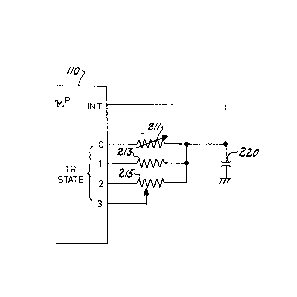
Figure 2 illustrates a circuit similar to the
circuit illustrated in Figure 1 for measuring the
resistance of a thermistor 211. Figure 2 illustrates a RC
time circuit including a plurality of resistances and a
single capacitance, capacitor 220. Thermistor 211 is
connected between the tristate output line 0 of
microprocessor device 110 and capacitor 220. Similarly, a
high precision fixed resistor 213 is connected between
tristate output line 1 and the capacitor. Further, a
potentiometer 215 has its fixed resistance connected
between tristate output line 2 and the capacitor and its
variable resistance connected between tristate output
line 3 and the capacitor. Although a discharge circuit
such as transistor 144 is not illustrated in Figure 2, it
would be understood by those skilled in the art that such
MIL-200 --15 4F7
3 ~ 8
a discharge circuit could be employed.
The object of the invention illustrated in
Figure 2 is to increase the accuracy of temperature
measurement while reducing the need for precision
components. Precision fixed resistor 213 is the only
precision component required in this circuit. In
addition, a power supply regulator 120 having relatively
poor regulation can be employed with this circuit. The
use of precision fixed resistor 213 as the single
precision component reduces the cost of construction
because precision fixed resistors are much less expensive
than precision thermistors or precision fixed capacitors.
Measurement of the resistance of thermistor 211
occurs in a manner similar to that described above in
conjunction with the description of Figure 1. Capacitor
220 is discharged. This could occur through a discharge
device such as transistor 144 illustrated in Figure 1.
Because a discharge transistor such as transistor 144 has
a very low impedance very little time would be required
to discharge capacitor 220 using such a device.
Alternatively this discharge could occur by tying all of
the tristate output lines 0-3 to the ground potential by
applying a "0" output to these lines. This latter
technique is believed advantageous because it reduces the
need for components external to the microprocessor unit
MI.J-200 --16 4F /
3 7 8
110. secause such a discharge path would involve a much
higher impedance than a discharge transistor, care must
be taken to maintain this discharge condition for a
sufficientl~ long time. This period of time should be at
least seven times the time constant of the combined
discharge path and capacitor 220. Once the capacitor 220
has been sufficiently discharged, an indeterminate high
impedance output is applied to tristate output lines 1-3.
At the same time, a "1" output is applied to tristate
output line 0. At the same time an elapsed timer is
started in a manner similar to that described above. When
the voltage across capacitor 220 reaches the
predetermined threshold voltage of the interrupt input
INT of microprocessor unit 110, then the elapsed time on
the elapsed time counter corresponds to the resistance of
thermistor 211. This in turn corresponds to the
temperature at thermistor 211.
After this measurement has been made then a
second measurement is made. Firstly, capacitor 220 is
discharged in a manner similar to that described above.
Then capacitor 220 is charged via precision fixed
resistor 213. This is achieved by applying an
indeterminate high impedance output to tristate output
lines 0, 2 and 3 and by applying a digital "1" output to
tristate line 1. This applies the power supply voltage
MI~-20~ --17 4F7
~ ~17~78
across the AC circuit including precision fixed resistor
213 and capacitor 220. In the same manner as previously
described, the elapsed time is measured from the first
application of voltage across capacitor 220 until the
voltage across capacitor 220 exceeds the predetermined
threshold of ~he interrupt input INT. This elapsed time
is a measure of the resistance of precision fixed
resistor 213.
In accordance with the preferred embodiment, the
resistance selected for the precision fixed resistor 213
is approximately equal to the nominal value of the
resistance of thermistor 211 at a selected reference
temperature, such as 70 F. The arithmetic computational
capability of the microprocessor 110 is then used to
compute the ratio of the time constant measured through
thermistor 211 and the time constant measured through
precision resistor 213. This ratio of times gives an
indication of the ratio of the resistance of thermistor
211 to the resistance of precision fixed resistor 213.
The computation of this ratio has the advantageous effect
of eliminating sources of variability. The value of
capacitance 220 is the same for each measurement. In
addition, if these time constant measurements take place
sequentially, the power supply voltage of microprocessor
110 cannot change greatly during this interval. Thus the
MI~-2()0 --18 ~ 31 ~ ~ ~ 8 4F7
formation of this ratio serves to eliminate many of the
sources of inaccuracy of the measurement of the
resistance of thermistor 211. This serves to permit a
more precise measure of the temperature.
Figure 2 also illustrates connections for
determining the operator set position of a potentiometer.
This technique employs a ratio in the manner similar to
that described above in conjunction with measuring the
resistance of thermistor 211. First, capac tor 220 is
discharged. Then capacitor 220 is charged through the
fixed value of potentiometer 215. This is accomplished by
driving the tristate output line 2 to a digital "1" while
leaving the other tristate output lines at the
indeterminate high impedance state. Thus capacitor 220 is
charged through the fixed resistance of potentiometer
215. The time necessary for the voltage across capacitor
220 to reach the predetermined threshold of the interrupt
input is measured. Next, capacitor 220 is again
discharged. Capacitor 220 is then charged through the
variable portion of potentiometer 2150 This is
accomplished by setting the output of tristate output
line 3 to a digital "1 ", thereby applying the power
supply voltage to the variable wiper contact of the
potentiometer. At the same time, the other tristate
output lines are set to the high impedance state. Thus
MI~-200 --19 4F7
~17~8
capacitor 220 is charged only through the variable wiper
of potentiometer 215. Again, the amount of time for the
voltage across capacitor 220 to reach the predetermined
value of the interrupt input is measured. The output or
S set point of potentiometer ~15 is determined by forming
the ratio of the charge time through the wiper input to
the charge time through the fixed resistance. As in the
case of the measurement of the resistance of thermistor
211 described above, the taking of this ratio serves to
reduce the measurement error due to variable parameters.
In the case of the measurement of the set point of the
potentiometer, the same capacitor 220 is employed,
thereby eliminating any variability in the nominal value
o~ the capacitor. In addition, if these time and
measurements are taken sequentially, any variation in the
power supply voltage is minimized because the change in
power supply voltage over such a short period is small.
Figure 3 illustrates the flow chart of a program
for microprocessor unit 110. This program for
microprocessor unit 110 causes electronic thermostat 100
to be a simple manual set point thermostat. The manual
set point is set by the position of potentiometer 215.
Figure 3 illustrates program 300 in ~low chart
form. Program 300 is a continuous loop which is
continuously executed in order to provide thermostatic
f~ `
Ml~-2~G --~ 4~l
~L 3 1 ~ ~ 7 8
control of the selected heating unit or air conditioner.
The discussion of program 300 will begin with processing
block 301. Processing block 301 measures the time
constant of the RC circuit including precision fixed
resistor 213 and capacit~r 220. The manner of performing
this time measurement has been explained above, and will
be further explained in regard to subroutine 500. Program
300 next measures the time constant of the RC circuit
including thermistor 211 (processing block 302). This
time measurement takes place in a similar fashion. Next,
program 300 again measures the time constant of the RC
circuit including precision fixed resistor 213
(processing block 303). This second measurement through
precision fix register 213 is employed to further
minimize any effect due to the changing power supply
voltage.
Program 300 tests to determine whether the two
time constant measurements of the precision fixed
resistor 213 are within a predetermined error limit E
(decision block 304). This is determined by taking the
absolute value of the difference between the first time
constant value tRl and the second time constant value
tR2. These two measurements are within the error limit E
if this absolute value is less than E. If the two
measurements are not within this error limit E then
Mi~-20~ 1 4F7
l 317~78
program control passes to processing block 301 to measure
the time constant of the precision fixed resistor 213
again. Program 300 remains within this loop until the two
time constant measurements are within the predetermined
error limit E. This process assures that the measurement
conditions have not appreciably changed during the period
when the three time constant measurements are taken.
Once the measurements regarding the thermistor
time constant have been completed, Program 300 forms the
ratio of the thermistor time constant to the precision
fixed resistor time constant by the formula:
tTC = tT / tRl
where tTC is the corrected time constant of the
thermistor, tT is the uncorrected time constant of the
thermistor, and tRl is the first measured time constant
of the reference resistor. This ratio is next employed
with a look-up table in order to derive the measured
ambient temperature TA (processing block 306).
Program 300 next measures the set point of
potentiometer 215. This is accomplished by measuring the
time constant of the constant portion of potentiometer
215 (processing block 307). This is followed by the
measurement of the time constant through the
~`
MI~-200 --'2 ~ 3 7 8 4F7
potentiometer tap (processing block 308). Lastly, a
second measurement of the time constant through the
entire fixed portion of the potentiometer is made
(processing block 309).
Program 300 then makes a test similar to that
indicated above in relation to the measurement of the
time constant of the thermistor. Program 300 tests to
determine if the absolute value of the difference between
the first measured time constant of the potentiometer tpl
and the second measured time constant of the
potentiometer tp2 is less than a predetermined error
limit E (decision block 310). If it is not, then the
measurement process is repeated. As previously described
Program 300 remains in this loop until the measurement is
complete.
A ratio is then formed in the microprocessor of
the time constant measured (processing block 311). This
ratio is similar to the ratio previously described for
determination of the temperature measured by the
thermistor. This ratio is calculated as follows:
tS = tTp / tPl
where ts is the corrected set point measured by the
potentiometer tap, tTp is the uncorrected time constant
through the potentiometer tap, and tpl is the first
MIL-20() --23 4F7
~3~7~78
measurement of the time constant through the fixed
portion of the potentiometer. Program 300 then reso~ts to
a look-up table to convert this ratio to the set point
temperature TS (decision block 312).
Program 300 then performs the thermostatic
control. This is shown embodied by an illustrative
subroutine 320. Subroutine 320 is a simple example of
thermos~atic control employing the sensing circuits of
the present invention. Those skilled in the art would
recognize that the sensing circuits of the present
invention could be employed with other thermostatic
control processes.
Subroutine 320 of program 300 determines whether
or not the electronic thermostat 100 is in heating mode
(decision block 321 ). ~his heating mode is set via
keyboard 115 in conjunction with the position of
heat/cool mode switch 135 to determine the particular
algorithm employed. If the electronic thermostat 100 is
in heat mode then program 300 tests to determine whether
or not the ambient temperature is less than the set point
temperature (decision block 322). If this is the case
then the triac 133 is triggered on (processing block 323)
in order to activate heating unit 20 and raise the
temperature. On the other hand, if the ambient
temperature is not less than the set point then triac 133
MI~-200 --2~ ~ 31 7 ~ 7 8 4F7
is not triggered ON (processing block 324). In thi~ event
lt is not necessary to operate heating unit 20 to raise
the temperature above the set point temperature.
If the electronic thermostat 100 is not in the
heating mode then program 300 tests to determine whether
or not the ambient temperature is greater than the set
point temperature (decision block 325). In the event that
the ambient temperature is greater than the set point
temperature then triac 133 is triggered ON (decision
block 323). In conjunction with the position of heat/cool
mode switch 135, this serves to turn on air conditioner
30 to lower the temperature. If the ambient temperature
is not greater than the set point temperature then
program 300 does not trigger triac 133 ON (processing
block 324). Thus air conditioner 30 is not actuated
because it is not needed.
Program 400 illustrated in Figure 4 is a flow
chart of the manner in which the time constants are
measured in program 300. Subroutine 400 is employed to
embody processing blocks 301, 302, 303, 307, 308 and 309
illustrated in Figure 3. Subroutine 400 is begun at start
block 401. Subroutine 400 first discharges capacitor 220
(processing block 402). This could take place with the
use of an external device such as transistor 144
illustrated in Figure 1 or via the tristate output lines
MI~-200 --25 ~ 3 ~ 7 3 7 ~ 4F7
0-3. Next, an index variable i is initialized (processing
block 403). The capacitor 220 is then charged via the
particular element J (processing block 404) by actuation
of the proper tristate output line 0-3. Subroutine 400
then increments the index variable i (processing block
405). Next, subroutine 400 tests to determine whether or
not the voltage across capacitor 220 Vc is greater than
or equal to the threshold voltage (decision block 406).
If this i6 not the case then the measurement is not
complete and subroutine 400 returns to processing block
405. If this is the case then the measurement is
complete. The measured time for the element J tJ is set
equal to the index variable i (processing block 407).
Subroutine 400 is then complete and is exited via end
block 408.
In a practical embodiment of subroutine 400, the
incrementing step 405 would be performed by adding 1 to a
memory register within microprocessor unit 110. The
processing of determining whether or not the voltage
across the capacitor Vc exceeds the predetermined
threshold of decision block 406 can be employed via the
interrupt input of INT microprocessor device 110. Thus
for example the incrementing of the index variable i can
occur within a closed loop and this loop be broken only
at the receipt of the interrupt. The interrupt is
MI~-200 --26 ~ 31 73 78 4F7
detected when the voltage across the capacitor exceeds
the predetermined ~hreshold of the interrupt input INT.
Because this interrupt input INT typically includes a
Schmidt trigger device, there is very little time between
the time at which the voltage crosses the threshold
voltage and the qeneration of the interrupt. This
interrupt signal stops the incrementing of the index
variable i and causes this value to be stored as the
measured time. Thus the clock which controls the rate of
operation of the microprocessor device 110 serves as a
timer to time the number of increments of the index
variable i.