Language selection

Search

Patent 1317562 Summary

Third-party information liability

Some of the information on this Web page has been provided by external sources. The Government of Canada is not responsible for the accuracy, reliability or currency of the information supplied by external sources. Users wishing to rely upon this information should consult directly with the source of the information. Content provided by external sources is not subject to official languages, privacy and accessibility requirements.

Claims and Abstract availability

Any discrepancies in the text and image of the Claims and Abstract are due to differing posting times. Text of the Claims and Abstract are posted:

  • At the time the application is open to public inspection;
  • At the time of issue of the patent (grant).
(12) Patent: (11) CA 1317562
(21) Application Number: 1317562
(54) English Title: METHOD AND APPARATUS FOR STRIPPING ELECTROLYTIC PRECIPITATE FROM SUPPORTING STRUCTURES
(54) French Title: METHODE ET APPAREIL SERVANT A RETIRER DES PRECIPITES ELECTROLIQUES DE LEUR SUPPORT
Status: Term Expired - Post Grant
Bibliographic Data
(51) International Patent Classification (IPC):
  • C25C 7/08 (2006.01)
(72) Inventors :
  • LEIPONEN, MATTI OLAVI (Finland)
  • ERLAMO, SEPPO JUHANI (Finland)
  • KUJANPAA, PENTTI KAARLO (Finland)
  • YLIMAKI, OLLI ERKKI (Finland)
(73) Owners :
  • OUTOKUMPU OY
(71) Applicants :
  • OUTOKUMPU OY (Finland)
(74) Agent: NORTON ROSE FULBRIGHT CANADA LLP/S.E.N.C.R.L., S.R.L.
(74) Associate agent:
(45) Issued: 1993-05-11
(22) Filed Date: 1987-10-01
Availability of licence: N/A
Dedicated to the Public: N/A
(25) Language of filing: English

Patent Cooperation Treaty (PCT): No

(30) Application Priority Data:
Application No. Country/Territory Date
864000 (Finland) 1986-10-03

Abstracts

English Abstract


(57) ABSTRACT
The invention relates to a method and apparatus for stripping
a thin, sheet-like layer of electrolytically accumulated
metal precipitate (6) from its supporting structures (1) by
means of a peeling blade (4) driven towards the upper edge of
the precipitate layer (6). For the stripping operation, the
supporting structure (1) is first attached to the stripping
station by aid of gripping members (2, 3), the frame whereof
advantageously provides a housing in common with the peeling
blades (4). Moreover, the measuring and control members (7,
8) which are advantageously located in the common housing, are
used in determining the surface profile of the supporting
structure (1), and the obtained profile is made use of while
choosing the orientation of the peeling blade (4).


Claims

Note: Claims are shown in the official language in which they were submitted.

The embodiments of the invention in which an exclusive
property or privilege is claimed are defined as follows:
1. A method for stripping a thin, sheet-like
layer of electrolytically accumulated metal precipi-
tate from a supporting structure, comprising attach-
ing the supporting structure to a stripping station
by means of gripping members, using measuring and
control members to determine a surface profile of the
supporting structure, orienting a peeling blade in
accordance with the surface profile and moving the
peeling blade in accordance with the surface profile
toward an upper edge of said sheet-like layer.
2. The method of claim 1 and including
gripping and supporting structure with said gripping
members near an upper edge of said sheet-like layer.
3. The method of claim 1 or 2 and including
using said gripping members in determining said
surface profile.
4. The method of claim 1 or 2 and including
moving the peeling blade essentially vertically from
a position near said upper edge.
5. The method of claim 1 or 2 and including
driving the peeling blade close to the surface of
said supporting structure during stripping.
6. The method of claim 5 and including
driving the peeling blade both vertically and toward
the surface of the supporting structure.

7. The method of claim 3 and including moving
the peeling blade essentially vertically from a
position near said upper edge.
8. The method of claim 3 and including
driving the peeling blade close to the surface of
said supporting structure during stripping.
9. The method of claim 3 and including
driving the peeling blade both vertically and toward
the surface of the supporting structure.
10. An apparatus for stripping a thin, sheet-
like layer of electrolytically deposited metal
precipitate from a supporting structure, comprising
gripping members for attaching the supporting struc-
ture to a frame at a stripping station, measuring and
control members for determining a surface profile of
said supporting structure, means for orienting a
peeling blade in accordance with a measured surface
profile of said supporting structure and means for
moving the peeling blade toward an upper edge of said
sheet-like layer in accordance with said surface
profile.
11. The apparatus of claim 10 wherein said
frame supports said peeling blade.
12. The apparatus of claim 11 wherein said
frame houses said control members.

13. The apparatus of claim 10, 11 or 12 and
including stripping blades on opposite sides of said
supporting structure for stripping a sheet-like layer
off two opposite sides of said supporting structure.

Description

Note: Descriptions are shown in the official language in which they were submitted.


1317~6~
The present invention relates to a me-thod and
appara-tus for stripping thin, sheet-like layers of
electrolytically accumulated metal precipitate from
supporting structures such as a cathode sheet or a
mother sheet by employing a peeling blade which is
advantageously drlven towards the upper edge of the
precipitate.
In the electrolytic production of metal, such as
zinc, it is customary to use an aluminium cathode
sheet, on the surface whereof the metal layer is
precipitated. The metaL layer is stripped after the
layer has reached sufficient thickness. In the
stripping procedure there is commonly used a strip-
ping machine comprising a peeling unit. The peeling
unit wedges an aperture at the upper edge of the
metal layer, whereafter the layer can be stripped in
the stripping unit proper.
In the method described in U.S. Patent 3,689,396, the
knife-like blades are driven under the metallic
precipitate at the side edge by employing a hinged
plastic guard, which prevents the metal precipitate
from accumulating in the corner of the cathode sheet.
In order to strip the metal layer, the guard member
is opened, and the blades have access below the
precipitate layer through the aperture formed under
the guard member. However, the cathode sheets are
easily corroded under the guard members, which
considerably shortens the working age of the cathode
sheets. Hence the cathode sheets and their produc-
tion bring about remarkable expenses.

~ 3~ 7~2
The present invention seeks to obviate some of the
drawbacks of the prior art and to achieve an improved
and cheaper method and apparatus for stripping metal
precipitates from their supporting structures.
In accordance with one aspect of the invention there
is provided a method for stripping a thin, sheet-like
layer of electrolytically accumulated metal precipi-
tate from a supporting structure, comprising attach-
ing the supporting structure to a stripping stati.on
by means of gripping members, using measuring and
control members to determine a surface profile of the
supporting structure, orienting a peeling blade in
accordance with the surface profile and moving the
peeling blade in accordance with the surface profile
toward an upper edge of said sheet-like layer.
In accordance with another aspect of the invention
there is provided an apparatus :Eor stripping a thin,
sheet-like layer of electrolytically deposited metal
precipitate from a supporting structure, comprising
gripping members for attaching the supporting struc-
ture to a frame at a stripping station, measuring and
control members for determining a surface profile of
said supporting structure, means for orienting a
peeling blade in accordance with a measured surface
profile of said supporting structure and means for
moving the peeling blade toward an upper edge of said
sheet-like layer in accordance with said surface
profile.

~317562
In order to perform an advantageous stripping according to the
inventlon, the cathode sheet comprising the metal precipitate
1s firmly attached at the top edge by means of gripping
memhers which form the frame guiding the peeling blades. The
position of the ~ripping members with respect to the cathode
sheet is advantageously chosen so that the jaws lock the
cathode sheet on both sides of the corroded zone caused by the
solution boundary of the electrolysis, so that the tor~ues
created in connection with the stripping do not turn or bend
the cathode sheet. Moreover, the gripping members are
employed for measuring, by aid of intermediate members, the
depth of the corrosion in order to define the profile of the
cathode sheet. On the basis of the obtained profile, the
movement of the peeling blades is guided in conformity to the
shape o~ the corrosion, so that the peeling blades move
advantageously along the sur~ace of the cathode sheet both in
height and in depth, thus preventing any cutting of the
cathode sheet which would lead to further damage.
The peeling blades of the apparatus of the inventlon are
advantageously knife-like blades which are sticked in between
the metal precipitate and the cathode sheet on both sides o
the sheet. The peeling blades wedge an advantageous aperture
in between the metal precipitate and the cathode sheet, which
is made use of in stripping the metal precipitate.
According to the invention, the metal precipitate is stripped
off the cathode sheet with a minimum wearing of the cathode,
whereby the working age of the cathode sheet is lengthened and
the expenses caused by the sheets are essentially reduced.
Moreover, work safety can be essentially improved~ because now
hazardous situations caused by damaged sheets arise more
rarely than before, the probability of damaged sheets thus
being minimized.
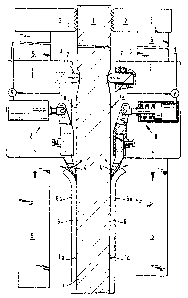
The lnvention 1s de~cribed in more detail with referen~e ~o
the appended drawings, wherein
Figure 1 is a side-view illustration o~ a preferred embodiment

~317~62
of the invention;
Figure 2 is a side-view illustration of the peeling blade of
the embodiment o~ figure l; and
Figure 3 is a front-view illustration of the peeling blade of
the embodiment of figure 1.
For an advantageous reallzation of the method of the
invention, the cathode sheet 1 lifted from the elecrolytic
bath is washed and conveyed to the stripping station according
to figure 1. In the stripping station the cathode sheet ~ is
fastened on both sides of the upper edge by means of two-part
gripping members 2 and 3. The gripping members 2 and 3 are
interconnected by aid of the frame 5, which at the same time
serves as the housing for the peeling blades employed in the
stripping procedure.
Before the stripping procedure proper~ there is determined the
profile of the cathode sheet 1, possibly deviating from a
straight planar surface and formed of earlier removed metal
precipitate layers and/or caused by the solution boundary of
the electrolysis. The determination of the profile la is car~ied
out by means of the meaSULing members ~ and control members 8,
attached to the frame above the precipitate layer 6 formed on
the cathode sheet 1. On -the basis of the measured surface
profile of the cathode sheet, the position of the peeling
blades 4 with respect to the frame 5 for starting the
stripping is chosen so that any wearing of the cathode sheet 1
owing to the stripping of the precipitate layer 6 can be
essentially avoided.
The peeling blades q employed in the stripping are, as is
apparent from figures 2 and 3, knife-like in shape and have an
advantageously bluntish and narrow point. The stripping
motion o the peeling blades 4 is advantageously started
vertically near the upper edge of the precipitate layer 6a, and
the blades are driven, controlled by the control members 8,
along the determined surface profile of the cathode sheet 1 so
that the points of the peeling blades 9 are kept essentially
near to the sheet surface also in the corroded zone of the sheet 1.

~3~75~2
Thus the peeling blades are essentially simultaneously driven
both vertlcally and in depth ln order to achieve an
advantageous realizatlon of the invention.
... .. .. ... . ~ ... .. ........ ... ... ~ . . . ..... . .. . . . . .. . .. , .. . ...... .. .... ...... ...... . . ~
.. .... .. ..... . . .... . . .. .. ... . .. ..... ..

Representative Drawing
A single figure which represents the drawing illustrating the invention.
Administrative Status

2024-08-01:As part of the Next Generation Patents (NGP) transition, the Canadian Patents Database (CPD) now contains a more detailed Event History, which replicates the Event Log of our new back-office solution.

Please note that "Inactive:" events refers to events no longer in use in our new back-office solution.

For a clearer understanding of the status of the application/patent presented on this page, the site Disclaimer , as well as the definitions for Patent , Event History , Maintenance Fee  and Payment History  should be consulted.

Event History

Description Date
Inactive: Expired (old Act Patent) latest possible expiry date 2010-05-11
Grant by Issuance 1993-05-11

Abandonment History

There is no abandonment history.

Owners on Record

Note: Records showing the ownership history in alphabetical order.

Current Owners on Record
OUTOKUMPU OY
Past Owners on Record
MATTI OLAVI LEIPONEN
OLLI ERKKI YLIMAKI
PENTTI KAARLO KUJANPAA
SEPPO JUHANI ERLAMO
Past Owners that do not appear in the "Owners on Record" listing will appear in other documentation within the application.
Documents

To view selected files, please enter reCAPTCHA code :


To view images, click a link in the Document Description column. To download the documents, select one or more checkboxes in the first column and then click the "Download Selected in PDF format (Zip Archive)" or the "Download Selected as Single PDF" button.

List of published and non-published patent-specific documents on the CPD .

If you have any difficulty accessing content, you can call the Client Service Centre at 1-866-997-1936 or send them an e-mail at CIPO Client Service Centre.


Document
Description 
Date
(yyyy-mm-dd) 
Number of pages   Size of Image (KB) 
Abstract 1993-11-30 1 19
Cover Page 1993-11-30 1 16
Drawings 1993-11-30 2 53
Claims 1993-11-30 3 62
Descriptions 1993-11-30 5 161
Representative drawing 2001-08-17 1 17
Fees 1997-04-14 1 47
Fees 1996-04-15 1 68
Fees 1995-04-12 1 85
Examiner Requisition 1991-06-18 1 53
Prosecution correspondence 1991-10-16 2 43
PCT Correspondence 1993-02-17 1 31
Courtesy - Office Letter 1987-12-11 1 37