Language selection

Search

Patent 1317614 Summary

Third-party information liability

Some of the information on this Web page has been provided by external sources. The Government of Canada is not responsible for the accuracy, reliability or currency of the information supplied by external sources. Users wishing to rely upon this information should consult directly with the source of the information. Content provided by external sources is not subject to official languages, privacy and accessibility requirements.

Claims and Abstract availability

Any discrepancies in the text and image of the Claims and Abstract are due to differing posting times. Text of the Claims and Abstract are posted:

  • At the time the application is open to public inspection;
  • At the time of issue of the patent (grant).
(12) Patent: (11) CA 1317614
(21) Application Number: 1317614
(54) English Title: ROTATING DRUM END SEAL
(54) French Title: OBTURATEUR DE TAMBOUR ROTATIF
Status: Term Expired - Post Grant
Bibliographic Data
(51) International Patent Classification (IPC):
  • F16J 15/46 (2006.01)
  • B01D 33/073 (2006.01)
  • F16J 15/34 (2006.01)
(72) Inventors :
  • BARDSLEY, DONALD E. (United States of America)
(73) Owners :
  • GL&V CANADA INC.
(71) Applicants :
  • GL&V CANADA INC. (Canada)
(74) Agent: NORTON ROSE FULBRIGHT CANADA LLP/S.E.N.C.R.L., S.R.L.
(74) Associate agent:
(45) Issued: 1993-05-11
(22) Filed Date: 1989-06-12
Availability of licence: N/A
Dedicated to the Public: N/A
(25) Language of filing: English

Patent Cooperation Treaty (PCT): No

(30) Application Priority Data:
Application No. Country/Territory Date
209,597 (United States of America) 1988-06-22

Abstracts

English Abstract


Docket No. 0319-IR-PA
ROTATING DRUM END SEAL
Abstract of the Disclosure
The seal has particular use as a seal in vats having a
rotatable drum. The seal prevents material from getting
between the ends of the drum and adjacent vat inside
surface.


Claims

Note: Claims are shown in the official language in which they were submitted.

The embodiments of the invention in which an exclusive
property or privilege is claimed are defined as follows:
1. In combination
a vat; a rotatable drum mounted in the vat; a
circumferential, inflatable tube retainer at each end of the
rotatable drum extending at least partially around the
circumference of the rotatable drum and located between the
end of the rotatable drum and the inside surface of the vat;
each circumferential, inflatable tube retainer having an
inside surface extending at an acute angle with respect to
the axis of the rotatable drum; a circumferential wear shoe
with a generally triangular cross-section at each end of the
drum in sealing contact with the drum along a first side of
the wear shoe, a second side of the wear shoe facing and
parallel to said inside surface of the circumferential,
inflatable tube retainer, said second side having a generally
semi-cylindrical groove extending along the length of the
wear shoe; an inflatable tube located in each wear shoe
generally semi-cylindrical groove and in contact with said
inflatable tube retainer inside surface; and a wear shoe
retainer having a surface in contact with the third side of
the wear shoe.

Description

Note: Descriptions are shown in the official language in which they were submitted.


1317614
.
Docket No. 0319-IR-PA
This invention relates to rotatable vacuum or pressure
washer drums used for washing pulp in pulp mills.
More particularly, this invention is a seal between the
rotatable drum and an adjacent stationary member to separate
a particular area of the vat from another particular area.
Pneumatic and hydraulic seals are available today but lack
certain qualities for proper functionO In addition, they
normally seal in a unidirectional way.
The seal structure of this invention is a new and novel
sealing arrangement between each end of the rotatable drum
and an adjacent stationary member of the vat. The seal
arrangement has the unique property of sealing in a
bi-directional way.
Briefly described, a rotatable drum is mounted in a vat. A
fixed circumferential, inflatable tube retainer is located
at each end of the vat and adjacent the end of the rotatable
drum. The inflatable tube retainer extends at least
partially around the circumference of the rGtatable drum.
Each circumferential, inflatable tube retainer has an inside
surface extending at an acute angle with respect to the axis
of the rotatable drum. A circumferential wear shoe with a
generally triangular cross-section is located at each end of
the vat, with one side in sealing contact with the corres-
ponding drum end. A second side faces and is parallel with
the inside surface of the circumferential, inflatable tube
retainer. The second side has a generally semi-cylindrical
groove extending along the length of the wear shoe. An
inflatable tube is located in the groove and is in contact
with the inflatable tube~ retainer inside surface. A wear
shoe retainer contacts the third side of the wear shoe and
:
....
,~

t317614
Docket No. 0319-IR-PA
keeps the wear shoe in place.
The invention, as well as its many advantages, will be
further understood by reference to the following detailed
description and drawings in which:
FIG. 1 is a side elevational view, partly in section,
showing the use of the new seal in a vat used for the
washing of pulp;
FIG. 2 is a view taken along lines 2--2 of FIG. 1 and in
the direction of the arrows and illustrating the circumfe-
rential positioning of the sealing arrangement;
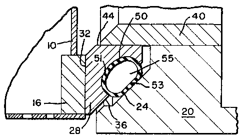
FIG. 3 is an enlarged sectional view, showing the de-
tails of the sealing structure of the embodiment of FIG. l
and FIG. 2; and
FIG. 4 is a view similar to FIG. 3, but showing the
change in dimensions of the wear shoe and inflatable tube
as the wear shoe wears;
In the various figures, like parts are referred to by like
numbers.
Referring to the drawings and more particularly to FIG. 1, a
rotatable drum 10 is mounted for rotation within a vat 12.
In operation, a pulp slurry is fed into the vat. A differ-
ential pressure is applied across~the drum by, for example,
a vacuum on the inside of the drum to form a pulp mat 11.
Filtrate drawn into a screen or deck 14 flows from the drum
through filtrate outlet 13. A seal 15, (shown schematic-
; ally), is provided at each axial end of the drum. One seal
wilI be described. It is to be understood that the other
:
-2-
,~-
:: , .: : . ., -
'
: : ' ~ ' . : :
.

1 31 76 1 4
Docket No. 0319-IR-PA
seal has the same structure as the described seal.
As shown in FIG. 3, the rotatable drum is provided with an
end ring 16. ~n inflatable tube retainer 20 for retaining
an inflatable tube is connected to end wall 21 of the vat
(see FIG. 1). As can be seen from looking at FIG. 2, the
inflatable tube retainer 20 which is fixed to the vat 12
extends approximately half way around the circumference of
the drum 10. The retainer 20 has an inside surface 24, (see
FIG. 3) which extends at an acute angle with respect to the
lQ axis of the rotatable drum.
Wear shoe 28 is located adjacent the axial end of the rota-
table drum 10. In the embodiment shown, the wear shoe does
not rotate and extends around approximately half the circum-
ference of the drum. The wear shoe is generally triangular
in cross section. The side 32 of the wear shoe 28, is in
sealing contact with the end ring 16, of the rotatable drum
10. Side 36 of the wear shoe 28, faces the inside surface
24, of the inflatable tube retainer 20. Side 36 is also
parallel to the inside surface 24. The wear shoe retainer 40
which keeps the wear shoe in place contacts the surface 44
of the wear shoe 28.
The side 36 of the wear shoe 28 is provided with a generally
semi-cylindrical groove 50. Located within the groove 50 is
an inflatable tube 55. The pressure within the inflatable
tube keeps its outside surface in contact with the surface
of groove 50 and the inside surface 24 of retainer 20. When
first installed surface 51 in contact with the groove 50 is
; arcuate and side 53 in contact with the inside surface 24 of
` the inflatable tube retainer 20 is ~lat ~see FIG. 3).
The seal has particular use when it is desired to separate
-3-
. . .
.~ ~
.

1317614
Docket No. 0319-IR-PA
or exclude one particular area of the vat from another par-
ticular area of the vat. For example, if the vat is used
for washing pulp, it is highly important that the pulp
fibers not get between the end of the rotatable drum 10 and
the end of the vat 12. Fibers bekween the end of the drum
and the vat would act like a brake. The pressure within the
inflatable tube causes a force to be directed against the
end ring on the rotatable drum and also against the bottom
~; surface of the wear shoe retainer 40. Thus, the inflatable
seal has the unique property of applying a sealing force in
a bi-directional way. As the wear shoe wears, the inflat-
able seal will change from an approximate elliptical instal-
lation configuration to a more circular configuration as
shown in FIG. 4 while still maintaining a seal at all times.
:
~ -4-
:
:: . . : ~ .:
:. , ' ,'' ~
~ ' . ~ :
:
~ .

Representative Drawing
A single figure which represents the drawing illustrating the invention.
Administrative Status

2024-08-01:As part of the Next Generation Patents (NGP) transition, the Canadian Patents Database (CPD) now contains a more detailed Event History, which replicates the Event Log of our new back-office solution.

Please note that "Inactive:" events refers to events no longer in use in our new back-office solution.

For a clearer understanding of the status of the application/patent presented on this page, the site Disclaimer , as well as the definitions for Patent , Event History , Maintenance Fee  and Payment History  should be consulted.

Event History

Description Date
Inactive: Expired (old Act Patent) latest possible expiry date 2010-05-11
Letter Sent 2009-06-19
Inactive: IPC from MCD 2006-03-11
Letter Sent 2003-10-10
Grant by Issuance 1993-05-11

Abandonment History

There is no abandonment history.

Owners on Record

Note: Records showing the ownership history in alphabetical order.

Current Owners on Record
GL&V CANADA INC.
Past Owners on Record
DONALD E. BARDSLEY
Past Owners that do not appear in the "Owners on Record" listing will appear in other documentation within the application.
Documents

To view selected files, please enter reCAPTCHA code :


To view images, click a link in the Document Description column. To download the documents, select one or more checkboxes in the first column and then click the "Download Selected in PDF format (Zip Archive)" or the "Download Selected as Single PDF" button.

List of published and non-published patent-specific documents on the CPD .

If you have any difficulty accessing content, you can call the Client Service Centre at 1-866-997-1936 or send them an e-mail at CIPO Client Service Centre.


Document
Description 
Date
(yyyy-mm-dd) 
Number of pages   Size of Image (KB) 
Cover Page 1993-11-15 1 23
Abstract 1993-11-15 1 18
Drawings 1993-11-15 2 69
Claims 1993-11-15 1 31
Descriptions 1993-11-15 4 147
Representative drawing 2001-08-01 1 15
Courtesy - Certificate of registration (related document(s)) 2009-06-19 1 103
Fees 1997-04-21 1 74
Fees 1996-04-16 1 30
Fees 1995-04-12 1 32
Examiner Requisition 1992-01-31 1 47
PCT Correspondence 1993-02-22 1 25
Prosecution correspondence 1992-05-22 2 44