Language selection

Search

Patent 1317831 Summary

Third-party information liability

Some of the information on this Web page has been provided by external sources. The Government of Canada is not responsible for the accuracy, reliability or currency of the information supplied by external sources. Users wishing to rely upon this information should consult directly with the source of the information. Content provided by external sources is not subject to official languages, privacy and accessibility requirements.

Claims and Abstract availability

Any discrepancies in the text and image of the Claims and Abstract are due to differing posting times. Text of the Claims and Abstract are posted:

  • At the time the application is open to public inspection;
  • At the time of issue of the patent (grant).
(12) Patent: (11) CA 1317831
(21) Application Number: 1317831
(54) English Title: ENGINE INDUCTION SYSTEM
(54) French Title: SYSTEME D'ADMISSION DU MELANGE AIR-COMBUSTIBLE D'UN MOTEUR
Status: Expired and beyond the Period of Reversal
Bibliographic Data
(51) International Patent Classification (IPC):
  • B60K 13/02 (2006.01)
  • F02M 35/10 (2006.01)
(72) Inventors :
  • BITTER, RUDOLF (Germany)
  • SENFF, GUNTER (Germany)
(73) Owners :
  • GENERAL MOTORS CORPORATION
(71) Applicants :
  • GENERAL MOTORS CORPORATION (United States of America)
(74) Agent: GOWLING WLG (CANADA) LLP
(74) Associate agent:
(45) Issued: 1993-05-18
(22) Filed Date: 1988-12-09
Availability of licence: N/A
Dedicated to the Public: N/A
(25) Language of filing: English

Patent Cooperation Treaty (PCT): No

(30) Application Priority Data:
Application No. Country/Territory Date
274,247 (United States of America) 1988-11-21
G 87 16 461.2 (Germany) 1987-12-12

Abstracts

English Abstract


C-4029
ENGINE INDUCTION SYSTEM
Abstract of the Disclosure
An internal combustion engine has a tuned
induction system with an air cleaner connected by a
conduit with a separate plenum mounted on a manifold
with individual runners connecting with the engine
cylinders. A throttle body having a throttle to
control induction air flow is located between the
plenum and the manifold with its runners such that the
plenum is not subject to reduced manifold pressures
resulting from throttling the air flow.


Claims

Note: Claims are shown in the official language in which they were submitted.

Claims
The embodiments of the invention in which an
exclusive property or privilege is claimed are defined
as follows:
1. An internal combustion engine having an
induction system with a plenum disposed upstream of
intake runners, said plenum being connected in series
with an upstream air filter and having a throttle body
with a throttle valve to control intake air flow,
characterized in that the throttle body (9) is located
directly at the outlet of the plenum (10) between the
plenum (10) and a manifold including the intake runners
(7,8).
2. An internal combustion engine according to
Claim 1, characterized in that the throttle body (9),
along with the manifold and intake runners (7,8) is
mounted on the cylinder head (2), and that the plenum
(10) is set directly on the throttle body (9).
3. An internal combustion engine according to
Claim 2, characterized in that the throttle body (9)
opens into the plenum (10) at a location spaced from
the side walls of the plenum (10).

4. An internal combustion engine having an
induction system with a plenum disposed upstream of and
defining a sole flow path to intake runners, said
plenum being connected in series with an upstream air
filter and having a throttle body with a throttle valve
to control intake air flow, wherein the throttle body
(9) is located at the outlet of the plenum (10) between
the plenum (10) and a manifold including the intake
runners (7,8).

Description

Note: Descriptions are shown in the official language in which they were submitted.


~3~783~
~-2716 C-4029
ENGINE INDUCTION SYSTEM
_.
Technical Field
The invention relates to tuned induction
systems for internal combustion engines of the type in
which a~collector or plenum preceding individual intake
runners is connected to an air filter, and in which a
throttle body with a throttle valve is provided in
order to control the air flow. An internal combustion
engine with an induction system of this type is shown
in United States patent 4,628,873.
~ackground
In the known internal combustion engine, the
plenum is attached to an end wall of the motor vehicle
engine compartment. Relatively long intake runners
lead rectilinearly from the plenum to the cylinder
head. A throttle body with a throttle valve to control
the quantity of air is provided at the inlet of the
plenum. ~he air inducted by the internal combustion
enyine flows from an air intake tube throuyh an air
filter and the throttle body into the plenum, and from
there through the individual intake runners into
associated combustion chamhers of the internal
combustion engine.
The configuration o the intake system
ac~ording to the above-mentioned U.S. patent 4,628,873
provides relatively long intake headers running
rectilinearly, which leads to advantageous gas velocity
conditions. This results in an increase in torque at
low engine speeds, and reduces undesirable exhaust and
noise emissions.
For reasons concerning the environmental
compatibility of motor vehicles, it is advantageous if
they are operated at relatively low enyine speeds.

13 1 ~
However, drivers take advantage of the ability to drive
at low to medium engine speeds only if sufficient
torgue is also available at the same time.
Summary of the Invention
An object of the invention is therefore that
of conf~gurinq an internal combustion engine with a
tuned induction system of the kind mentioned initially
in such a way that the engine has the highest possible
torque at medium to low engine speeds.
According to the invention, this object is
obtained by locating throttle body at the outlet of the
plenum between the plenum and an intake manifold with
individual runners.
This very simple configuration results,
surprisingly, in a definite improvement in the torque
of the internal combustion engine at medium to low
engine speeds. In addition, there is a reduction in
noise and a decrease in noxious components in the
exhaust. A reason for these positive effects is
assumed to be the fact that in the arrangement
according to the invention, air can flow into the
throttle body from a large-volume, unpressurized/
non-turbulent plenum volume. In the plenum of the
internal combustion engine according to the
25 above-mentioned patent 4,628,873 the pressure in the
plenum is influenced by changes in the setting of the
throttle valve and by the intake vacuum of the internal
combustion engine, so that the plenum pressure
fluctuates.
In one desirable embodiment of the invention,
the throttle body along with the intake manifold is
mounted on the cylinder head, and the plenum is set
directly on the throttle body. With this

~ ~ 7~
configuration, it is not necessary to attach the plenum
to one wall of the engine compartment, so that the
assembly process is simpler.
Air can flow from all dir~ctions from the
plenum into the throttle body in a uniform manner if
the throttle body opens into the plenum at a distance
from the side walls of the plenum.
The invention may have many embodiments, one
of which is illustrated in the drawing and is described
below.
Brief Drawing Description
In the drawing:
Figure 1 shows a partially sectioned end view
of an internal combustion engine according to the
invention and;
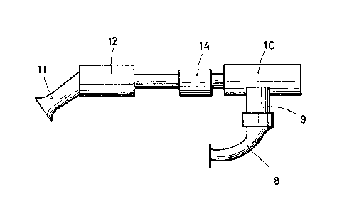
Figure 2 shows schematically a portion of the
induction system of the internal combustion engine
according to Figure 1.
Detailed Description
The internal combustion engine shown in Figure
1 has a cylinder block 1 on which is mounted a cylinder
head 2, with exhaust and intake valves 5, 6
respectively, controlled by camshafts 3, 4.
To the right of the cylinder head 2 in the
drawing is an ,ntake manifold with runners 7, 8 which
connects upwardly with a throttle body 9. An intake
plenum 10 is mounted on the throttle body 9.
Combustion air drawn in by the internal combustion
engine flows through an intake tube 11 into an air
filter 12, rom there through a conduit 13 into an
airflow meter 14, and then into the plenum 10, from
which it passes through the throttle body 9 into the
intake manifold and runners 7, 8. The engine is a

13~7~
fuel-injection internal combustion engine having
injectors 15, by means of which fuel is injected into
the intake runners 7, 8 as shown in Figure 1.
Figure 2 shows how air flows from the intake
tube 11 to one of the intake runners 8. Note that the
throttle~ body 9 opens into the plenum 10 at a distance
from the side walls of the plenum 10. As a result, air
can flow uniformly from all sides into the throttle
body 9.

Representative Drawing
A single figure which represents the drawing illustrating the invention.
Administrative Status

2024-08-01:As part of the Next Generation Patents (NGP) transition, the Canadian Patents Database (CPD) now contains a more detailed Event History, which replicates the Event Log of our new back-office solution.

Please note that "Inactive:" events refers to events no longer in use in our new back-office solution.

For a clearer understanding of the status of the application/patent presented on this page, the site Disclaimer , as well as the definitions for Patent , Event History , Maintenance Fee  and Payment History  should be consulted.

Event History

Description Date
Time Limit for Reversal Expired 1997-05-20
Letter Sent 1996-05-20
Grant by Issuance 1993-05-18

Abandonment History

There is no abandonment history.

Owners on Record

Note: Records showing the ownership history in alphabetical order.

Current Owners on Record
GENERAL MOTORS CORPORATION
Past Owners on Record
GUNTER SENFF
RUDOLF BITTER
Past Owners that do not appear in the "Owners on Record" listing will appear in other documentation within the application.
Documents

To view selected files, please enter reCAPTCHA code :


To view images, click a link in the Document Description column. To download the documents, select one or more checkboxes in the first column and then click the "Download Selected in PDF format (Zip Archive)" or the "Download Selected as Single PDF" button.

List of published and non-published patent-specific documents on the CPD .

If you have any difficulty accessing content, you can call the Client Service Centre at 1-866-997-1936 or send them an e-mail at CIPO Client Service Centre.


Document
Description 
Date
(yyyy-mm-dd) 
Number of pages   Size of Image (KB) 
Abstract 1993-11-15 1 13
Claims 1993-11-15 2 35
Drawings 1993-11-15 1 52
Descriptions 1993-11-15 4 112
Representative drawing 2001-12-26 1 7
Fees 1995-05-03 1 38
Prosecution correspondence 1991-07-03 1 31
PCT Correspondence 1993-02-28 1 23
Courtesy - Office Letter 1989-03-22 1 35
Examiner Requisition 1991-04-02 1 32