Language selection

Search

Patent 1318119 Summary

Third-party information liability

Some of the information on this Web page has been provided by external sources. The Government of Canada is not responsible for the accuracy, reliability or currency of the information supplied by external sources. Users wishing to rely upon this information should consult directly with the source of the information. Content provided by external sources is not subject to official languages, privacy and accessibility requirements.

Claims and Abstract availability

Any discrepancies in the text and image of the Claims and Abstract are due to differing posting times. Text of the Claims and Abstract are posted:

  • At the time the application is open to public inspection;
  • At the time of issue of the patent (grant).
(12) Patent: (11) CA 1318119
(21) Application Number: 1318119
(54) English Title: SAFETY RAZORS
(54) French Title: RASOIR DE SURETE
Status: Term Expired - Post Grant
Bibliographic Data
(51) International Patent Classification (IPC):
  • B26B 21/00 (2006.01)
  • B26B 21/40 (2006.01)
(72) Inventors :
  • OLDROYD, BRIAN (United Kingdom)
(73) Owners :
  • THE GILLETTE COMPANY
(71) Applicants :
  • THE GILLETTE COMPANY (United States of America)
(74) Agent: MACRAE & CO.
(74) Associate agent:
(45) Issued: 1993-05-25
(22) Filed Date: 1988-07-27
Availability of licence: N/A
Dedicated to the Public: N/A
(25) Language of filing: English

Patent Cooperation Treaty (PCT): No

(30) Application Priority Data: None

Abstracts

English Abstract


ABSTRACT
A safety razor comprising a flexible razor blade unit
secured to a handle by a connection arranged to permit free
flexure of the unit in use of the razor. The connection
comprises a slide for mounting and guiding the unit for
reciprocal movement relative to the handle in a direction
substantially perpendicular to the planes of the blades, the
slide being located at the mid-length of the unit, and further
connections, to either side of the slide, permitting relative
movement of opposite end portions of the unit, relative to the
handle, in directions generally parallel with the blade edges.
With this arrangement, the slide serves to centralize the unit
longitudinally on the handle, whilst permitting free movement of
the central part of the unit towards and away from the handle
and the further connections which are conveniently formed as pin
and slot connections permit concomitant movement of the opposite
end portions of the unit towards and away from each other.


Claims

Note: Claims are shown in the official language in which they were submitted.

THE EMBODIMENTS OF THE INVENTION IN WHICH AN EXCLUSIVE
PROPERTY OR PRIVILEGE IS CLAIMED ARE DEFINED AS FOLLOWS:
1. A safety razor comprising a razor blade unit
which is readily flexible, in response to forces
encountered during normal use, about an axis or axes
parallel with the plane of the blade and extending
substantially perpendicular to the cutting edge of the
blade, a handle and connecting means connecting the
unit to the handle, the said connecting means
comprising slide means for mounting and guiding the
unit for reciprocal movement relative to the handle in
a direction substantially perpendicular to the plane
of the blade, the slide means being located at the
mid-length of the unit, and further connections, to
either side of the slide means, permitting relative
movement of opposite end portions of the unit,
relative to the handle in directions generally
parallel to the blade edge.
2. A razor according to claim 1, wherein the said
slide means comprises a post extending essentially
perpendicular to the said plane and a socket in which
the post is slidably engaged.
3. A razor according to claim 2, wherein the post
and the socket are both of non-circular cross-section
to prevent relative rotation therebetween.
9. A razor according to claim 2 or 3, wherein the
said post is aligned with a central region of the unit
in which the main forces encountered during shaving
are directed.

5. A razor according to any one of claims 1, 2 or 3,
wherein said further connections each comprise a pin engaging
in a socket with freedom to slide laterally therein, in
directions generally parallel with the blade edge, but
constrained against substantial relative movement in
directions perpendicular to the plane of the blade.
6. A razor according to claim 4, wherein said further
connections each comprise a pin engaging in a socket with
freedom to slide laterally therein, in directions generally
parallel with the blade edge, but constrained against
substantial relative movement in directions perpendicular to
the plane of the blade.
7. A razor according to claim 5, wherein the pins
extend parallel with the said axis or axes and have rounded
upper and lower edges to facilitate fixture of the unit about
the said axis or axes.
8. A razor according to claim 6, wherein the pins
extend parallel with the said axis or axes and have rounded
upper and lower edges to facilitate flexure of the unit about
the said axis or axes.
9. A razor according to claim 7 or 8, wherein the pins
are fast with the razor handle and engage in pockets formed in
the blade unit.
10. A razor according to any one of claims 1, 2, 3, 6,
7 or 8, wherein the said further connections are each set in
from the ends of the unit and are spaced apart by a distance
approximately two-thirds of the length of the unit.
11. A razor according to claim 4, wherein the said
further connections are each set in from the ends of the unit
and are spaced apart by a distance approximately two-thirds of
the length of the unit.

12. A razor according to claim 5, wherein the said
further connections are each set in from the ends of the unit
and are spaced apart by a distance approximately two-thirds of
the length of the unit.
13. A razor according to claim 9, wherein the said
further connections are each set in from the ends of the unit
and are spaced apart by a distance approximately two-thirds of
the length of the unit.

Description

Note: Descriptions are shown in the official language in which they were submitted.


` ~
~3~
Safety Razors
~his in-ention relate6 to safet~ razors oS th(
kno~n form comprising a flexible ra70~ blade unit ~ecured
to a handle by connecting means arran~cd to permit. f~ee
flexure o~ the unit ir use of the razor.
The blade unit is flexible in the sense that is
readily flexible, in response to forces encountered during
normal use, about an axis or axes parallel with the plane
of the blade (or blades) and extendin~ substantiall~ per-
- pendicular to the cut.ting edge ~or edges) thereof.
' ~he present invention is particular~.concerned
with the means b~ ~hich such a unit. is connect d t.o a razor
handle so as to be adequatel, supported and guided thereon
whi~st permitting the required flexure of the unit in use.
~or convenience of description, the blade unit
~ill be assumed to be a tandem blade unit, ha in~ a pair
of parallel blades ~hose respect.i~e cu~tinF ed~es are he]d
in spaced paral~el relation, so as to act in tandem on the
s~in of the user.
In a presentl~ preferred form vf the in ention,
the eonllection means romprise slide means for mounting and
guiding the unit for reciprocal mo ement relative to the
handle in a direction substantially perpendicular to the
planes of the blades, the slide means being located at the
mid-length of the unit, and further connections, to either
~side of the slide means, permitting relative movement ~f
~'

oppnsite end por~ion~ Or the unit, relative to the hand]e,
in directions generally parallel with the b~ade edges.
hith this ~rrangement, the slide ~eans serve to
centralise the unit longitudinally on the handle, whilst
S permitting f`ree movement of the central part of the unit
tohards and a~ay frQm the handle and the further connectlons~
~hich are con eniently formed as pin and slot connections
permit concomitant mo~ement of the opposite end portions of
th unit to~ards and aha~ from eac}- oth(:r.
1~ ~his form of the in~ention h'i] ~ no~ be deseribed
in detaj], b~ ~a~ of examp]e, with referer,ce to the a com-
pan~ing drahi nos, i n ~hieh:
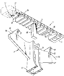
~ i~. I is a perspecti~e ~ie~, from belo~ Or the
handle and blade unit, both partly broken ahay, prior to
'5 assembly;
Fig. 2 is a perspective vieh from below the
handle assemb~ed hith the unit, hhich is sho~n in phanto~,
~ine~
Fi~. 3 is a cross-section of the assembled razor;
and
Fi~. 4 is a scrap rear vie~ of the assemb~ed
razor.
7he illustrated razor comprises a flexible head
or blade unit ~ including a tandem pair of wafer thin
~5 sin~e ed~ed b~ades 2 separated b~ a spacer and set perm-
anentl in a hi~h3~ f]exib~e moulded p]astic~ support
structule 3 pro~idinF a comb-like skin guard 4 ahcad of ar,d
belo~ the b~ade edges and a segmented cap portion 5 o er-
~in~ the b~ade pair.
3~ ~he razor handle is constituted by a unitary
moulding of plastics material formed to pro~ide an elongate
grip portion 6 and a generally plate-~ike upper portion 7
on which the blade unit I is mounted.
The conrlection means include a slide means com-
prising a central post 10 of rectangular cross-section which

~ 3 ~
dep~nds ~.rom the under6ide of the b~ade unit snd extends
substanti~ly perp~ndicular to the p~anes of the bladec at
the mid-len6th of the blade unit, and a pocket 11 formed at
the upper end of the handle. ~he pocket is also of rectan-
S gular cross-section and is sized to receive the post l~
with an easy sliding fit.
hith the post ~ocated in the pocket, the b]ade
uni~ is cerltralized ~ongitudina~ly re~ati~e to the hand]e
an~ r~stiained rr n, lotating a~out 1hc harldle, but. is guid~
'~ ~c-r eas~ ~liuin~ mo~em nt tohalds and aha! fr(lln ~l hand]e.
in t he direction o~ the length of the yost ]~.
~ urther connections are m~de to eithel side- of
the central post 10 which permit and constrain the opposite
end portions of the unit to move, relative to the handle,
'5 towards and a~ay from each other, generally para~lel to the
blade edges.
~ he handle upper porti on 7 is formed hith respec-
ti e su~port legs ]2 each ~.erminating at a for~ardly
project.ing pin 13 of part rounded cross-section. ~n the
20 assembled razor, the pins ]3 are located in and trapped by
rearhardly facing pockets l4 formed at the underside of
the support structure 3. ~he pockets 14 are con eniently
formed bet.~een adjacent ribs 15 of the struct.ure 3 and
short bridgin~ portions 1~ interconnecting tht said ribs.
. 25 As best seel) in ~ig. 4, the depth of each poc~et
approxima-es ~o the deplh of the corresponding pin ]~ ~hose
up~er and ~o~er rounded edges are ~ocated against the upper
and loher faces of the poc~et. ~he ~idth of the pocket is,
hohe er-, greater than that of the pin so as to permit move-
3~ ment of the pocket relative to the pin in a direction
generally parallel to the blade edges. Engagement. of the
pins in the pockets also retains the blade unit against
removal from the handle. The upper rounded edges of the
legs l~ and pins 13 engage against the underside of ~ebs
35 ~7 spanning a~jacent ribs iS-

3 3 ;L ~ ~ ~ e~
4 -
irlitial ~s~em~ly of the uniS with the handle i~
readily eff`ect.ed by engaging the centre post Ininthe guide
pocket 11 and pressing the unit tohards the handle in the
regions of the ~egs 1?., the pins 13 snapping into the pockets
14, thanks to the f~exibility and resilier-ce of the compo-
nent.s. ~he illustrated razor i~ intended to be disposable,
but the connection means illustrated may readily be modified
to cater for remo a] and replacement of the blade units on a
permanent handle.
'~ The unil is thus se ure~ r~tain~d to the hand]e
b~ col-nectiol~ mearls of er~ simple cc)nstrl3ct.ion, but retaills
its hi~h de~lee o~ flexibi]~t.y, reduced on]~ b~ the er~
small frict.iona] resistances t.o s~id~n~ bet~een t.ht compo-
nent.s.
'5 The support legs 12 are each set in from the end~
of the blade unit, their spacing apart bein~ approximatel~
2/3 of the length of the unit, so as to permit the unit to
def~ect con exly if one or both ends encounter lar~er forces
in use than the medial sect.ion. ~he unit can~ of course,
deflect. conca el~ if more force is encountered in the medial
section.
In the conca~e mode, deflection is limit.ed b~
abutment of the underside of the blade unit with the upper
end of the central p~rtion of the handle. and in t.he con~e~
mode b~ the underside of the cartrid~e abuttin~ the upper
ed~es 1~ of the out.er ends of the portion 7.
In the particular embodiment. il~ustrated~ conca-e
deflection is ~imited to 2.5 mm at the centre, and in the
con~ex mode, deflection of the end portions of the unit is
3n limited to 3 mm, both measured from the neutral, unstressed
condition of the unit.
The main forces encountered durin~ sha~ing are
directed perpendicular to the planes of the blades, and
pass through a region bordered by the cutting edges of the
blades. ~or thi6 reason, the post 10 is ali~ned ~ith that

1 3 ~ $ ~
region, s~ as to minimi6e an~ tendenc~ Svr the post 1~ to
be subjected to any bending movements ~hich ~uld tend to
cause it to bind in it.s pocket 11.
ln the case of a single blad unit, the post is
aligned ~ith the cutting edge of the b]ade.
1 ~

Representative Drawing
A single figure which represents the drawing illustrating the invention.
Administrative Status

2024-08-01:As part of the Next Generation Patents (NGP) transition, the Canadian Patents Database (CPD) now contains a more detailed Event History, which replicates the Event Log of our new back-office solution.

Please note that "Inactive:" events refers to events no longer in use in our new back-office solution.

For a clearer understanding of the status of the application/patent presented on this page, the site Disclaimer , as well as the definitions for Patent , Event History , Maintenance Fee  and Payment History  should be consulted.

Event History

Description Date
Inactive: Expired (old Act Patent) latest possible expiry date 2010-05-25
Inactive: IPC from MCD 2006-03-11
Grant by Issuance 1993-05-25

Abandonment History

There is no abandonment history.

Owners on Record

Note: Records showing the ownership history in alphabetical order.

Current Owners on Record
THE GILLETTE COMPANY
Past Owners on Record
BRIAN OLDROYD
Past Owners that do not appear in the "Owners on Record" listing will appear in other documentation within the application.
Documents

To view selected files, please enter reCAPTCHA code :


To view images, click a link in the Document Description column (Temporarily unavailable). To download the documents, select one or more checkboxes in the first column and then click the "Download Selected in PDF format (Zip Archive)" or the "Download Selected as Single PDF" button.

List of published and non-published patent-specific documents on the CPD .

If you have any difficulty accessing content, you can call the Client Service Centre at 1-866-997-1936 or send them an e-mail at CIPO Client Service Centre.


Document
Description 
Date
(yyyy-mm-dd) 
Number of pages   Size of Image (KB) 
Cover Page 1993-11-15 1 10
Abstract 1993-11-15 1 21
Drawings 1993-11-15 3 51
Claims 1993-11-15 3 79
Descriptions 1993-11-15 5 141
Representative drawing 2001-07-26 1 13
Fees 1995-04-17 1 64
Fees 1997-04-13 1 82
Fees 1996-04-14 1 72
Courtesy - Office Letter 1988-11-06 1 42
PCT Correspondence 1993-03-07 1 23
Prosecution correspondence 1992-09-17 1 34
Examiner Requisition 1992-07-20 1 59
Prosecution correspondence 1990-11-25 3 57
Examiner Requisition 1990-10-04 1 46