Language selection

Search

Patent 1318145 Summary

Third-party information liability

Some of the information on this Web page has been provided by external sources. The Government of Canada is not responsible for the accuracy, reliability or currency of the information supplied by external sources. Users wishing to rely upon this information should consult directly with the source of the information. Content provided by external sources is not subject to official languages, privacy and accessibility requirements.

Claims and Abstract availability

Any discrepancies in the text and image of the Claims and Abstract are due to differing posting times. Text of the Claims and Abstract are posted:

  • At the time the application is open to public inspection;
  • At the time of issue of the patent (grant).
(12) Patent: (11) CA 1318145
(21) Application Number: 1318145
(54) English Title: PIN-TUMBLER LOCK
(54) French Title: SERRURE A BARILLET
Status: Expired and beyond the Period of Reversal
Bibliographic Data
(51) International Patent Classification (IPC):
  • E05B 27/04 (2006.01)
  • E05B 27/00 (2006.01)
(72) Inventors :
  • EISEN, NOAH (Israel)
(73) Owners :
  • MUL-T-LOCK LTD.
(71) Applicants :
  • MUL-T-LOCK LTD. (Israel)
(74) Agent: CASSAN MACLEAN
(74) Associate agent:
(45) Issued: 1993-05-25
(22) Filed Date: 1988-06-30
Availability of licence: N/A
Dedicated to the Public: N/A
(25) Language of filing: English

Patent Cooperation Treaty (PCT): No

(30) Application Priority Data:
Application No. Country/Territory Date
83071 (Israel) 1987-07-03

Abstracts

English Abstract


A B S T R A C T
A pin tumbler lock comprising a shell with cylindrical hole,
a cylindrical plug fitting within said hole of said shell,
said plug rotatable by key means, said plug having first
bore means for receiving first pin tumblers, said first bore
means being substantially normal to the axis of the plug,
said shell having second bore means for receiving second pin
tumblers therein, said second bore means being aligned with
said first bore means, first pin tumblers in said first bore
means, second pin tumblers in said second bore means, and
means in said shell for forcing said second pin tumblers
into said aligned first bores to thereby prevent rotation of
said plug, first and second pin tumblers having
substantially mating surfaces at their points of contact,
chacterized that said plug comprises two grooves normal to
the axis of said plug, one groove on each side adjacent said
first bore means, and said first and second tumbler pins
mate at least partially within said grooves in the plug,
thereby providing a non-linear shear line between said plug
and said shell.


Claims

Note: Claims are shown in the official language in which they were submitted.

THE EMBODIMENTS OF THE INVENTION IN WHICH AN EXCLUSIVE
PROPERTY OR PRIVILEGE IS CLAIMED ARE DEFINED AS FOLLOWS:
1. A pin tumbler lock comprising a shell with
cylindrical hole, a cylindrical plug fitting within said
hole of said shell, said plug being rotatable by key means,
said plug having first bore means for receiving first pin
tumblers, said first bore means being substantially normal
to the axis of the plug, said shell having second bore
means for receiving second pin tumblers therein, said
second bore means being aligned with said first bore means,
first pin tumblers in said first bore means, second pin
tumblers in second bore means, and means in said shell for
normally forcing said second pin tumblers into said aligned
first bore means to thereby prevent rotation of the said
plug, said first and second pin tumblers having
substantially mating surfaces at their points of contact,
wherein said plug comprises two grooves normal to the axis
of said plug, one of said grooves being provided on each
side adjacent said first bore means, and said first and
second tumbler pins mate at least partially within said
grooves in the plug, thereby providing a non-linear shear
line between said plug and said shell.
2. A pin tumbler lock in accordance with claim 1

wherein the grooves encircle the plug normal to the plug
axis.
3. A pin tumbler lock in accordance with claim 1
wherein the second pin tumbler in the shell comprises a
concave mating surface.
4. A pin tumbler lock in accordance with claim 3
wherein the first and second pin tumblers mate at their
contact surface in a convex-concave relationship
respectively.
5. A pin tumbler lock according to any one of claims 1
to 4 wherein the lock is a dual pin tumbler lock comprising
telescopic pin tumblers.
6. A pin tumbler lock according to any one of claims 1
to 4 wherein the means in the shell for forcing the second
pin tumblers into the first bores comprises spring means.
7. A pin tumbler in accordance with claim 1, 2 or 3
wherein all the first bore means of the plug comprise

grooves adjacent to either side of said first bore means.
8. A pin tumbler lock comprising a shell with
cylindrical hole, a cylindrical plug fitting within said
hole of said shell, said plug being rotatable by key means,
said plug having first bore means for receiving first pin
tumblers, said first bore means being substantially normal
to the axis of said plug, said shell having second bore
means for receiving second pin tumblers therein, said
second bore means being aligned with said first bore means,
first pin tumblers in said first bore means, second pin
tumblers in said second bore means, and means in said shell
for forcing said second pin tumblers into said aligned
first bores to thereby prevent rotation of said plug, said
first and second pin tumblers having at the respective ends
contacting each other substantially mating surfaces to
provide contact substantially along entire surface of the
contacting ends, said plug comprising two substantially
parallel grooves each extending in a plane normal to the
axis of said plug and along the periphery of said plug, one
of said plug, one of said grooves being provided on each
opposite side of said first bore means, along the
longitudinal axis of said plug and adjacent said first bore
means, and said first and second tumbler pins being
rotatable independently of one another and mating at least
partially within said grooves in said plug, thereby

providing a non-linear shear line between said plug and
said shell irrespective of the circumferential position of
said pins, said bore means and said plug.
9. A pin tumbler lock according to claim 8 wherein said
mating surfaces include a convex surface on said first pin
tumbler and a corresponding concave surface on said second
pin tumbler.
10. A pin tumbler lock according to claim 8 wherein the
lock is a dual pin tumbler lock including telescopic pin
tumblers independent of one another located in a telescopic
arrangement.
11. A pin tumbler lock according to claim 9 wherein the
lock is a dual pin tumbler lock including telescopic pin
tumblers independent of one another located in a telescopic
arrangement.
12. A pin tumbler lock according to claim 8 wherein said
means in said shell for forcing said second pin tumblers
into said first bore means comprises spring means.

13. A pin tumbler lock according to claim 9 wherein said
means in said shell for forcing said second pin tumblers
into said first bore means comprises spring means.
14. A pin tumbler lock according to claim 8 wherein said
bore means includes plurality of bores in said plug with
said grooves being provided adjacent both opposite sides of
each of said boxes along the axis of said plug.
15. A pin tumbler lock according to claim 9 wherein said
bore means includes plurality of bores in said plug with
said grooves being provided adjacent both opposite sides of
each of said bores along the axis of said plug.
11

Description

Note: Descriptions are shown in the official language in which they were submitted.


l'~lg^~
The present invention concerns a pin tumbler cylin~er lock
which is more resistant to picking than the cylinder loclcs
of this type known heretofore.
Cylinder locks generally comprise a number of pin tumbler~
spring loaded within bores which must be depres~ed by the
proper projections in the key in order for the plug of the
lock to be rotated within the shield.
The bores in the plug and shell, due to manufacturiny
limitations, always vary in diameter. In cylinder locks the
holes are drilled. The tool for drill bits doing the work
is quite long in relation to its diameter. ~lso because of
the flexibility of the drill and uneven consistencies in the
metal being drilled, and because -they are not perEectly
formed at the cutting edges, these drilled usually drill
holes of varying diameters. Drills will also run off of a
true center line. These manufac-turing limitations cause the
whole inner plug and shell never to be matching exactly,
even in the most expensive and well made locks. Because of
these manufacturing defficiencies, lock picking is made
easier because once the end of the pin tumbler is aligned
with the shear line, a shil~ can be introduced to maintain
the separation of plug tumbler pins and shell tumbler pins.
As the next pair of tumbler pins are picked, the shim can be
advanced linearly to continue and maintain the separation
between the plu~ tumblers and shell tumblers, and so on

- 2 - 13~
until all oE the tumblers are separated along the shear line
with the shim maintaining this separation.
Locks of this type can also be picked without the use of a
shim as follows. Once the end of the pin tumbler is aligned
with the shear line, its position can be held by applying a
slight turning pressure on the plug~ As the next pair o~
tumbler pins is picked, slight further twisting of the plug
maintains the ends of the second pin tumblers aligned with
the shear line, and so on until all the tumbl0rs are
separated at the shear line and the plug can be rotated in
the shell. This is made possible by the loose fit of the
pin tumblers in the bores and by the non-mating surfaces o~
core and shell pin tumblers which is a direct result of
having a linear shear line.
This problem is more acute with dual pin tumbler locks,
since the bores and pin tumblers in such locks are of a
larger diameter than in single pin tumbler locks. Such a
IS~Qel
dual pin tumbler loc]c was disclosed in our~Patent No.
50984.
It is the object of the present invention to provide a
cylinder loc]c with a plug and pin tumblers that will make it
more di~ficult to pic]c.
The invention consists in a pin tumbler lock comprising a
shell with cylindrical hole, a cylindrical plug fitting

1 3 ~ 3 ~ ~
-- 3 --
within said hole of the shell, the plug rotatable by key
means, said plug having first bore means for receiving
first pin t~mblers, said fi:rst bore means being
substantially normal to the axis of the plug, said shell
having second bore means for recei.ving second pin tumblers
therein, said second bore means being aligned with said
first bore means, first pin tumblers in said first bore
means, second pin tumblers in said second bore means, and
means in said shell for normally forcing said second pin
tumblers into the aligned fi.rst bores to thereby prevent
rotation of said plug. The first and second pin tumblers
have substantially mat.ing surfaces at their points of
contact. The plug comprises two grooves normal to the axis
of the plug. One of the grooves is provided on each side
adjacent the first bore means. The first and second
tumbler pins mate at least partially within ~he grooves in
the plug, thereby providing a non-linear shear line between
said plug and said shell.
In a preferred embodiment, the second pin tumblers in the
shell comprise concave mating surfaces. This configuration
of the second pin tumblers permits the mating of the first
and second pin tumblers over their maximum contact surface
in a convex-concave relationship.
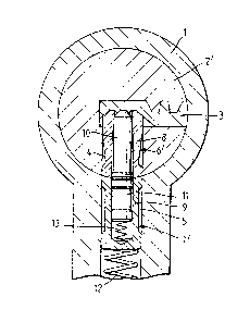
The invention is illustrated, by way of exa~lple only, in
the accompanying drawings in which:
!,r,'.`~.
, . .

3 ~ ~ q ~
Figure 1 is a vertical section or a prior art cylindér lock;
Figure 2 is a sectional view of the longitudinal
cross-section of the prior art cylinder lock of
Figure 1;
Figure 3 is a vertical section view of the cylinder lock o
the invention;
Figure 4 is a sectional view of the longitudinal
cross-section of the cylinder lock according to
- the invention; and
0 Figure 5 i5 an enlarged isometric cutout view of a plug and
pin tumbler according to the invention.
With reference to Figures 1 and 2r these locks comprise a
shell 1 in which a plug 2 is rotatable by means o a key 3
- as known per se~ The plug 2 is provided with a bore 4, and
the shell 1 with bore 5, each of these bores housing tumbler
pins 6 and 7 respectively. In the present illustration the
tumbler pins are constituted by two parts, i,e. tumbler pin
6 in the core co~prised of an outer cylindrical part 8 and
an inner part 10l and tumbler 7 in the shell comprised of an
outer cylindrical part 9 and an inner part 11. The outer and
inner pins 9 and 11 are urged by means o springs 12 and 13
respectively. Thus the inner pins 10 of the core and 11 o

- 5 - ~3~$~
the shell can move telescoplcally within their respective
outer cylindrical parts ~ and 9.
Referring now to Figures 3-5 which lllustrate the invention,
the plug 2I comprises grooves, 14 and 15, adjacent bore 4 of
plug 2'. This enables tumbler 6' in the plug 2', having a
convex contact surface, to mate lts counterpart tumbler pin
7'in shell 1, having a concave contact surface, along their
entire contact surface, 50 that tumblers 6'and 7' are
closely and maximumly engage~. The shear line 16 is
therefore not linear, but rather wavy, some parts beiny
linear along x (Figure 2) and others being curved along y.
This creates much less freedom of movement for the tumblers
around the shear line and requires more accurate matching of
the tumblers before the plugs will rotate within the shellO
Figure 5 shows OII an enlarged scale the grooves 1~ and 15 in
plug 2' and the mating pin tumblers 6' and 7'.
In the prior art locks shown in Figures 1 and 2, the plug
which is cylindrical in shape comprised a smooth linear
outer circumference. When such a plug is inserted into a
shell, there is formed a linear shear line 16' between the
plug 2 and shell 1. The outer tumblers 6 and 7 ar~ not
mated at their point of contact and a space 17 inherently
exists between the core and shell pin tumblers.

- 6 '~3 ~ 3
It is of course understood that the present lnvention is
also applicable to single pin tumbler locks and not only to
dual pin tumbler locks as exemplified.
The grooves on each side of the bore, as required by this
invention, can be in respect oE a single bore or in respect
of all the bores of the plug.

Representative Drawing
A single figure which represents the drawing illustrating the invention.
Administrative Status

2024-08-01:As part of the Next Generation Patents (NGP) transition, the Canadian Patents Database (CPD) now contains a more detailed Event History, which replicates the Event Log of our new back-office solution.

Please note that "Inactive:" events refers to events no longer in use in our new back-office solution.

For a clearer understanding of the status of the application/patent presented on this page, the site Disclaimer , as well as the definitions for Patent , Event History , Maintenance Fee  and Payment History  should be consulted.

Event History

Description Date
Time Limit for Reversal Expired 2009-05-25
Letter Sent 2008-05-26
Inactive: IPC from MCD 2006-03-11
Grant by Issuance 1993-05-25

Abandonment History

There is no abandonment history.

Owners on Record

Note: Records showing the ownership history in alphabetical order.

Current Owners on Record
MUL-T-LOCK LTD.
Past Owners on Record
NOAH EISEN
Past Owners that do not appear in the "Owners on Record" listing will appear in other documentation within the application.
Documents

To view selected files, please enter reCAPTCHA code :


To view images, click a link in the Document Description column. To download the documents, select one or more checkboxes in the first column and then click the "Download Selected in PDF format (Zip Archive)" or the "Download Selected as Single PDF" button.

List of published and non-published patent-specific documents on the CPD .

If you have any difficulty accessing content, you can call the Client Service Centre at 1-866-997-1936 or send them an e-mail at CIPO Client Service Centre.


Document
Description 
Date
(yyyy-mm-dd) 
Number of pages   Size of Image (KB) 
Claims 1993-11-16 5 133
Abstract 1993-11-16 1 27
Cover Page 1993-11-16 1 11
Drawings 1993-11-16 3 73
Descriptions 1993-11-16 6 160
Representative drawing 2002-02-18 1 12
Maintenance Fee Notice 2008-07-07 1 171
Fees 1997-04-17 1 72
Fees 1996-05-24 1 30
Fees 1995-05-18 1 34
Prosecution correspondence 1991-06-27 5 116
Examiner Requisition 1991-05-16 1 78
PCT Correspondence 1993-02-24 1 36
Courtesy - Office Letter 1988-11-25 1 29