Language selection

Search

Patent 1318234 Summary

Third-party information liability

Some of the information on this Web page has been provided by external sources. The Government of Canada is not responsible for the accuracy, reliability or currency of the information supplied by external sources. Users wishing to rely upon this information should consult directly with the source of the information. Content provided by external sources is not subject to official languages, privacy and accessibility requirements.

Claims and Abstract availability

Any discrepancies in the text and image of the Claims and Abstract are due to differing posting times. Text of the Claims and Abstract are posted:

  • At the time the application is open to public inspection;
  • At the time of issue of the patent (grant).
(12) Patent: (11) CA 1318234
(21) Application Number: 607067
(54) English Title: CASSETTE CONTAINING FLEXIBLE TUBING TO BE DISPENSED THEREFROM
(54) French Title: CASSETTE DE DISTRIBUTION DE TUYAU SOUPLE
Status: Deemed expired
Bibliographic Data
(52) Canadian Patent Classification (CPC):
  • 156/11
  • 217/5.5
(51) International Patent Classification (IPC):
  • B65B 9/15 (2006.01)
  • B65B 67/12 (2006.01)
  • B65F 1/06 (2006.01)
(72) Inventors :
  • RICHARDS, DAVID CHARLES (United Kingdom)
  • WILLIAMS, MAURICE STANLEY (United Kingdom)
  • WARD, BRIAN (United Kingdom)
  • RICHARDS, DAVID CHARLES (United Kingdom)
  • WILLIAMS, MAURICE STANLEY (United Kingdom)
  • WARD, BRIAN (United Kingdom)
(73) Owners :
  • MELROSE PRODUCTS LIMITED (United Kingdom)
(71) Applicants :
(74) Agent: FETHERSTONHAUGH & CO.
(74) Associate agent:
(45) Issued: 1993-05-25
(22) Filed Date: 1989-07-31
Availability of licence: N/A
(25) Language of filing: English

Patent Cooperation Treaty (PCT): No

(30) Application Priority Data:
Application No. Country/Territory Date
8818365.2 United Kingdom 1988-08-02

Abstracts

English Abstract


A CASSETTE CONTAINING FLEXIBLE TUBING
TO BE DISPENSED THEREFROM
In a cassette for dispensing flexible tubing, the
tubing is packed in a tightly layered mass between a
tubular core and the vertical wall of a casing.
Subsequently a cap is mounted in an expanded portion of
the casing. The cap has A vertical part fitting the
portion and a flange partially overlapping the pack. The
cap is secured against rising by punching tongues out of
the portion that engage in a groove in the part. The
inner surface of part aligns with surface of casing. The
junction beneath expanded portion prevents cap from
descending as the tubing is dispensed from the top of the
pack, over the core edge and through core.


Claims

Note: Claims are shown in the official language in which they were submitted.


THE EMBODIMENTS OF THE INVENTION IN WHICH THE EXCLUSIVE
PROPERTY OR PRIVILEGE IS CLAIMED ARE DEFINED AS FOLLOWS:

1. A cassette for use in dispensing flexible tubing
packed therein in layered form, the cassette comprising a
rigid body formed by a central tubular core open at top
and bottom, a surrounding casing wall positioned to
provide an annular space between said tubular core and
said casing wall and an annular base wall joining a lower
end of said surrounding casing wall to the lower end of
said tubular core, a length of non-resilient flexible
tubing packed profusely in a tightly layered mass in said
annular space to constitute a pack surrounding said
tubular core, a cap placed over said pack of tubing and
formed as an annular cap axially movable in said casing
and extending radially from said casing wall to a
location providing a gap between the inner edge of said
cap and said tubular core enabling said tubing to be
dispensed by passing from the top of said pack, between
said cap and said core, over the top edge of said core
and downwards through said core, and detent means
integral with said casing wall and projecting inwards
therefrom to engage said cap to limit movement of said
cap away from said pack.
2. A cassette according to Claim 1, in which said
detent means are protuberances distributed round
the internal surface of said casing wall.
3. A cassette according to Claim 2, in which said
protuberances are formed on said casing wall subsequently
to the mounting of said cap above said pack of tubing.


4. A cassette according to Claim 1, in which said
casing wall is cylindrical and is formed at its upper end
with a cylindrical portion of increased uniform diameter
and in which said cap is formed with a cylindrical
periphery that is a sliding fit in said cylindrical
portion of increased diameter whereby the unexpanded
portion of said casing wall limits any downward movement
of said cap in said casing wall.
5. A cassette according to Claim 4, in which said
cylindrical periphery of said cap is formed with an
internal peripheral surface of effectively the same
diameter as the internal surface of the unexpanded
portion of said casing wall.
6. A cassette according to Claim 2, in which said
protuberances distributed round the internal surface of
said casing wall are inwardly projecting tongues and in
which said cap is formed with a peripheral surface formed
with a groove to be engaged by said tongues.
7. A cassette according to Claim 3, in which said
protuberances distributed round the internal surface of
said casing wall are tongues bent inwards from the casing
wall by piercing means.

Description

Note: Descriptions are shown in the official language in which they were submitted.


`-` 1 31 8234


This inven~ion relates to a cassette containlng flexible
tubing to be dispensed therefrom. Such a cassette car be located
in a position from which the tubing is required and when the
tubing is exhausted, ~he cassette can readily and easily be
replaced by a similar full cassette. One situation in which such
a cassette can advantageously be used is packaging apparatus as
described in applicant's Canadian Patent No. 1,298,191.
One object of the invention is to provide a cassette
that is very well adapted for mass and rapid production by
~0 mechanical means and is compact yet capable of containing 100 ft
(30.4~ m) of tubing, for example.
According to the invention, a cassette containing
flexible substantially non-resillent tubing comprises a rigid body
having a central core open at top and bottom and a surrounding
casing joined to the lower end of the core by an annular base
wall, the tubing being packed profusely in a tightly layered mass
between the core and the casing and an annular cap placed over the
pack of tubing subsequently to the formation thereof and shaped to
extend inwards, from the periphery of the casing towards, but not
as far as, the core, detent means operative after mounting the cap
being provided on the casing for limiting upward movement of the
cap within the casing, the casset~e being arranged for the tubing
to be dispensed by passing from the top of the pack, between


B~

1 31 8234


the cap and core~ over the top edg~ of the core and
downwards through the core. One advantageous form of
detent means comprises tongues bent slightly inwards ~rom
the casing wall to engage the periphery of the cap so as
5 to limit upward movement of the cap. Such tongues maybe
formed from the casing wall after mounting the cap.
Alternatively the tongues maybe formed initially on the
casing wall for the cap to snap past them on being
mounted.
The cap may be formed with a cylindrical part and a
flange that projects over the pack ~rom the top of the
cylindrical part and the top of the casing may be
expanded to recei~e the cylindrical part. This
arrangement considerably facilitates the assembly of the
15 cassette and its use, when the diameter of the
cylindrical part is equal to the diameter of the
unexpanded portion of the casing. It is understood that
the terms ~top~ and ~hottom~ in this specification are
simply used to indicate the relative positions of the
20 parts of the cassette, the "top" being the area at which
the tubing is discharged from the pack. Obviously the
cassette may be mounted in a variety of positions, for
example, with its axis horiæontal.
In order that the invention may be clearly
25 understood and readily carried into effect a cassette for
dispensing flexible tubular material will now be
described, by way of example, with reference to the
accompanying drawings in which:-
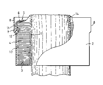
Figure 1 is a side elevation, partly in section,

t31823~


of the cassette;
Figure 2 is an enlargement of part of Figure 1,
showing more detail; and
Figure 3 is a front ele~ation of part of Figure 2.
Refexring to Figure 1, the body of the cassette
consists of a rigid moulding of plastics material
comprising a central cylindrical core 1, open at top and
bottom and a cylindrical casing 2, open at the top, and
having an annular base wall 3 joining the lower ends of
10 the core and casing.
Packed in the cassette between the core and casingis a mass or pack of profusely and tightly layered non-
resilient tubing 4, which may for example, be high
density polyethylene tubing.
After the tubing has been packed an annular cap 5
is placed over the pack of tubing 4. This cap 5 has a
top flange 6 that extends inwards towards, but not as far
as, the core 1 from a cylindrical part 7 that has a
portion bearing against the inner surface of an e~panded
20 pcrtion 8 of the casing 2. To prevent the cap 5 from
rising undesirably after it has been mounted, three
bevelled piercing tools 9 (Figure 2) distributed
equidistantly round the casing are simultaneously
operated to form three tongues 10 bent inwards from
25 portion 8 of the casing to engage in an annular V-shaped
groove 11 formed in the cylindrical part 7 of the cap 5.
When the cap is mounted, the tubing pack 4 is slightly
compressed and then immediately released whereupon the
groove 11 is lifted to the tongues 10.

`` t318234

It has proved highly desirable, both from the point of
view of the asse~bly of the cassette and of its use for the inner
cylindrical surface 12 of the cylindrical part 7 of the cap to
ha~e precisely the same diameter as the inner surface 13 of the
unexpanded portion of the casing 2.
In use the casse~te is mounted in a support or device
such as the packaging device described in applicant's Canadian
Patent No. 1,298,191 and the flexible tubing is pulled or pushed
(if the end of the tubing is first closed) through the core 1, the
tubing passing from the pack 4 between the flange 6 and core 1 and
then over the top edge of the core which is slightly expanded at
14 to provide a ~urved edge to avoid damage to the tubing.
As the flexible tubing is used, the pack shrinks
downwards and to prevent the cap 5 from descending and perhaps
getting wedged in the casing, the junction lS at the bottom of the
casing expansion 18 acts as a stop.
For tublng of approximately 8 or 9 inches (20 or 23 cm)
diameter, the diameter of the core 1 may be approximately 4 inches
(10.16 cm). These figures are, of course, only by way of example,
and a wide range of sizes is possible.
Various modifications of the cassette described above
may be made without departing from the scope of the following
claims. For example, in the case of a thermoplastic body dimples
may be formed inside the casing (by the external application of
hot points) to engage a circumferential groove on the cap.
Moreover, it is not essential for the tongues 10 to be formed
after the cap 5 has been inserted. They may constitute initial
portions of the body prior to filling. Then after the flexible


~j

` 1 3 1 823~


tubing has been packed, the cap is thrust into the body with
sufflcient force for its edge to snap past the tongues which will
then take up positions that prevent the cap from rising in the
body. Instead of tongues small dimples or other shallow
protuberances or even a shallow embossed ring may be formed on the
inside surface of the casing past which the cap is to snap on
being mounted.
Apparatus for packing cassettes as described above with
layered or pleated flexible tubing is described in our Canadian
Patent Application No. 2,019,173.

Representative Drawing
A single figure which represents the drawing illustrating the invention.
Administrative Status

For a clearer understanding of the status of the application/patent presented on this page, the site Disclaimer , as well as the definitions for Patent , Administrative Status , Maintenance Fee  and Payment History  should be consulted.

Administrative Status

Title Date
Forecasted Issue Date 1993-05-25
(22) Filed 1989-07-31
(45) Issued 1993-05-25
Deemed Expired 2010-05-25
Correction of Expired 2012-12-05

Abandonment History

There is no abandonment history.

Payment History

Fee Type Anniversary Year Due Date Amount Paid Paid Date
Application Fee $0.00 1989-07-31
Registration of a document - section 124 $0.00 1989-11-15
Registration of a document - section 124 $0.00 1992-11-20
Maintenance Fee - Patent - Old Act 2 1995-05-25 $100.00 1995-03-20
Maintenance Fee - Patent - Old Act 3 1996-05-27 $100.00 1996-04-15
Maintenance Fee - Patent - Old Act 4 1997-05-26 $100.00 1997-04-14
Maintenance Fee - Patent - Old Act 5 1998-05-25 $150.00 1998-04-14
Maintenance Fee - Patent - Old Act 6 1999-05-25 $150.00 1999-04-14
Maintenance Fee - Patent - Old Act 7 2000-05-25 $150.00 2000-04-13
Maintenance Fee - Patent - Old Act 8 2001-05-25 $150.00 2001-04-17
Maintenance Fee - Patent - Old Act 9 2002-05-27 $150.00 2002-04-16
Maintenance Fee - Patent - Old Act 10 2003-05-26 $200.00 2003-04-16
Maintenance Fee - Patent - Old Act 11 2004-05-25 $250.00 2004-04-13
Maintenance Fee - Patent - Old Act 12 2005-05-25 $250.00 2005-04-13
Maintenance Fee - Patent - Old Act 13 2006-05-25 $250.00 2006-04-13
Maintenance Fee - Patent - Old Act 14 2007-05-25 $250.00 2007-05-17
Maintenance Fee - Patent - Old Act 15 2008-05-26 $450.00 2008-04-16
Owners on Record

Note: Records showing the ownership history in alphabetical order.

Current Owners on Record
MELROSE PRODUCTS LIMITED
Past Owners on Record
PROCESS IMPROVEMENTS LIMITED
RICHARDS, DAVID CHARLES
WARD, BRIAN
WILLIAMS, MAURICE STANLEY
Past Owners that do not appear in the "Owners on Record" listing will appear in other documentation within the application.
Documents

To view selected files, please enter reCAPTCHA code :


To view images, click a link in the Document Description column. To download the documents, select one or more checkboxes in the first column and then click the "Download Selected in PDF format (Zip Archive)" or the "Download Selected as Single PDF" button.

List of published and non-published patent-specific documents on the CPD .

If you have any difficulty accessing content, you can call the Client Service Centre at 1-866-997-1936 or send them an e-mail at CIPO Client Service Centre.


Document
Description 
Date
(yyyy-mm-dd) 
Number of pages   Size of Image (KB) 
PCT Correspondence 1993-03-02 1 15
Prosecution Correspondence 1992-08-19 1 14
Examiner Requisition 1992-07-03 1 55
Prosecution Correspondence 1992-06-04 3 53
Examiner Requisition 1992-03-04 1 56
Representative Drawing 2001-12-28 1 14
Drawings 1993-11-16 1 30
Claims 1993-11-16 2 78
Abstract 1993-11-16 1 23
Cover Page 1993-11-16 1 16
Description 1993-11-16 5 175
Fees 1997-04-14 1 63
Fees 1996-04-15 1 46
Fees 1995-03-22 1 38