Note: Descriptions are shown in the official language in which they were submitted.
PATENT
1 31 839~1
BACKGROUND OF THE INVENTION
Field of the Invention
This invention relates generally to the driving of
stepping motors and, more particularly is directed to a
method of driving a stepping motor so as to make the latter
suitable for effecting tracking movements of a magnetic pick
up or head in respect to a magnetic disk, fQr example, as in
an electronic still camera.
DESCRIPTION OF THE PRIOR ART
In an existing electronic still camera, a rotated
magnetic disk is employed for the recording of video signals
corresponding to still pictures or images in respective
circular tracks on the magnetic disk. Usually, a magnetic
recording and/or reproducing head is carried by an arm
mounted for rectilinear movements substantially parallel to
a radius of the rotated magnetic disk so that the head can
be made to record and/or reproduce a video signal in a
selected circular track on the disk when such selected track
is traced by the head. Since the track pitch or radial
distance between adjacent tracks on the magnetic disk is
quite small, for example, 100 ~m, the movements of the arm
for causing tracking of the head in respect to a selected
track are minute, for example, of the order of 10 ~m.
Therefore, when a stepping motor is employed to effect the ` ~-
~rectilinear movements of the arm carrying the magnetic head
for tracking by the latter, it is conventional to provide
AS18:16mk -3-
PATEN~
39-0100.2134
1 31 83q7
reduction gearing between a rotor of the stepping motor and
a lead screw for propelling the rectilinearly movable arm.
However, problems arise when reduction gearing is interposed
between the rotor of the stepping motor and the mechanism by
which rotary movements of the rotor are converted into
rectilinear movements of the arm supporting the magnetic
head for effecting tracking. More specifically, the
pxesence of the reduction gearing increases the cost of the
apparatus and reduces the speed with which the tracking
movements of the magnetic head can be effected.
Furthermore, the positioning accuracy is deteriorated due to
backlash in the reduction gearing.
In order to improve the accuracy with which a
driven member can be positioned by a stepping motor, a
so-called micro-stepping method has been proposed for
driving the stepping motor. In accordance with such micro-
stepping method, a stepping motor having a rotor or driven
member and a plurality of phases or windings to which input
pulses are applied in predetermined seauences for
establishing excitation states by which the rotor is stepped
to respective positions, is operated so as to bring the
rotor to rest at a desired position intermediate stepped
positions which correspond to first and second excitation
states-,-respectively. For example, if the ratio of the
distances from the desired position of rest of the rotor to
the stepped positions corresponding to the first and second
AS18:16mk -~-
PA~ENT
39-0100.213
1 31 8397
excitation states, respectively, is 1:3, the first and
second excitation states are alternately employed with a
duty ratio of 3:1, that is, with a duty ratio which
inversely corresponds to the ratio of the distances from the
desired position of rest of~the rotor to the stepped
positions of the latter corresponding to the first and
second excitation states, respectivelyO Furthermore r the
frequency of the alternation between the first and second
excitation states is made sufficiently high so that the
rotox of the stepping motor and the system to be driven
thereby, such as, the rectilinearIy moveable head-supporting
arm, do not oscillate or vibrate in response to the
alternation of the excitation states.
However, the proposed micro-stepping method for
operating or driving a stepping mo~or is disadvan'ageous in
that the desired minute angular movement of the rotor of the
stepping motor may be absorbed by the backlash or play in
the system to be driven, for example, in the lead screw and
followe pln by which the arm supporting the magnetic head
is rec.ilinearly moved in response to turning OI th~ ro.or,
so that the head is not moved at all. In other words, even
if the rotor of the stepping motor is angularly displaced to
extent calculated to achieve precise tracking of a selected
track by the magnetic head, the actual movement of the head
may not precisely correspond to that angular displacement of
~S18:16mk -5-
PATENT
39-0100.2134
1 3 1 8397
the rotor due to mechanical play in the motion transmitting
system.
Although it has been suggested to employ a
so-called uni-directional feed in which, during the micro-
stepping operation of a stepping motor, the alternation
between first and second excitation states always starts
with the same one of such states, it has been found that
even such uni-directional feed does not reliably achieve the
accurate positioning of the head for tracking purposes due
to the mechanical loss or play in the motion transmitting
system.
OBJECTS AND SUMMARY OF THE INVENTION
Accordingly, it is an object of this invention to
provide a method and apparatus in which a stepping motor is
driven so as to precisely position the rotor between stepped
positions thereof, and which avoids the above described
disadvantages of the prior art.
More specifical1y, it is an object of .his
invention to provide a method and apparatus in which a
stepping motor is driven so as to achieve minute
displacements of a driven member, that is, displacements
smaller than those corresponding to the natural steps of the
rotor, without interposing reduction gearing between the
rotor and the driven member.
A further object is to provide a method and
apparatus in which a stepping motor is driven, as aforesaid,
AS18:16mk -6-
.
PATENT
39-0100.2134
~ 3 1 8397
by subdividing a natural step of the rotor is and a member
driven theraby is precisely positioned in correspondence to
such subdivision of the natural step.
In accordance with an aspect of this invention, in
driving a stepping motor having a driven member or rotor and
a plurality of phases to which input pulses are applied in
predetermined sequences for establishing excitation states
by which the driven member is stepped to respective
positions, the input pulses are applied so as to alternate
between first and second excitation states corresponding to
respective stepped positions which are adjacent each other
and between which it is desired to bring the driven member
to rest, with such alternation being initially effected at a
frequency at which the driven member or rotor is made to
oscillate between the stepped positions corresponding to
such first and second excitation states, respectively. Then,
the frequency of alternation between ~he-first and second
excitation states is gradually increased to a value at wnich
the driven member no longer oscillates with such alternation
and comes to rest at a position between the stepped
positions corresponding to the first and second excitation
states, respectively. A duty ratio is selected for the
first and second excitation states which inversely
corresponds to the ratio of the distances from the desired
position of rest of the driven member to the stepped
positions of the latter corresponding to the first and
AS18:16mk -7-
PATENT
39-0100.2134
1 31 8397 .~
second excitation states, respectively, and such duty ratio
is applied to the alternation between the first and second
excitation states at least during the increasing of the
frequency of alternation to the value at which the driven
member no longer oscillates.
In a preferred ~mbodiment of the invention, the
selected duty ratio which inversely corresponds to the ratio
of distances from the desired position of rest of the driven
member to the stepped positions of the latter corresponding
to the first and second excitation states, respec~ively, is
also applied to the alternation between the first and second
excitation states at the initially effected relatively low
frequency at which the driven me~ber, and any mechaniczl
transmission system coupled therewi.h is made to oscillate
between positions corresponding to .he first and second
excitation states, respectively. Such oscillation or
vibration of the driven member of the stepping motor and of
the mechanical tran~mission system coupled therewith exceeds
the mechanical play or loss in such transmission system. As
the rrequency of the alternation between the first and
second excitation states is gradually increased, while
maintaining the selected duty ra~io for the first and second
excitation states, the driven member of the stepping motor
and the mechanical transmission system drivén thereby
vibrate to a decreasing extent so that the mechanical play
is uniformly distributed at the opposite limits of the
AS18:16mk -8-
PATENT
39-0100.2134
1 31 8397
oscillation or vibration. When the frequency of alternation
between the first and second excitation states is increased
to the value at which the rotor or driven member no longer
oscillates with such alternation, the mechanical motion
transmission system is stopped precisely at the desired
position determined by the selected duty ratio.
The above, and other objects, features and
advantages of the invention, will be apparent in the
following detailed description of an illustrative embodiment
of the invention when read in connection with the
accompanying drawings forming a part hereof, and in which
corresponding parts are identified by the same reference
numerals in the several views of the drawings.
BRIEF DESCRIPTION OF THE D~WINGS
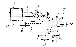
Fig. 1 is a front elevational view of a portion of
a known electronic still camera including a stepping motor
that may be advantageously driven in accordance with an
embodiment of this invention;
Fig. 2 is a side elevat~onal view OL the apparatus
shown in Fig. 1 as viewed in the direction indicAted by the
arrow II on that view;
Fig. 3 is a block diagram showing a driving
circuit that may be employed for driving the stepping motor
of the apparatus in Figs-. 1 and 2 in accordance with an
embodiment of this invention;
AS18:16mk -9-
PATENT
39-0100.2134
1 31 ~397
Fig. 4 is a schematic diagram illustrating the
directions of current flow through the phases of the
stepping motor in Fig. 3 for the various excitation states
achieved in the case of a two~phase excitation;
Fig~ 5 is a schematic diagram illustrating the
sequences in which input pulses are applied to the phases of
the stepping motor for the two-phase excitation;
Fig. 6A is a diagram illustrating the alternation
between two excitation states with a selected duty ratio in
accordance with an embodiment of this invention,
Fig. 6B is a diagram similar to of FigO 6A, but
showing a reversal of the order of the excitation states
between which the alternation occurs; and
Fig, 7 is a flow diagram to which reference will
be made in explaining the driving of a stepping motor in
accordance with this invention.
DESCRIPTION O~ A PREFERRED EMBODIMENT
Referring to the drawings in detail, and initially
to Figs. 1 and 2, it W7 11 be seen that the invention is
advantageously applicable to the drlving of a stepping motor
1 which is includ~d in an electronic still camera and which
has stator windings or phases lA and lB and a rotor lC [Fig.
3). The rotor lC of the stepping motor is directly coupled
to a lead screw 2 which, with a follower pin 4 extendin~ from
an arm 3 and engageable in a groove of the lead screw 2,
forms a mechanical transmission for converting rotary or
AS18:16mk ~10-
,
PATENT
39-0100.2134
1 31 83~7
angular movement~ of the rotor lC into rectilinear movements
of the arm 3 in the directions of the arrows LR on Fig. 1.
A magnetic head 5 is suitable situated on the arm 3 so as to
be movable along a radius of a rotated magnetic disk (not
shown) in response to the movements of the arm 3 in the
directions of the arrows L~ under the guiclance of guide rods
6 and 7. Additional mechanisms (not shown) are desirably
provided to prevent canting or swinging of the arm 3, ~or
example, angular displacements of the arm 3 relative to the
axis of the guide rod 6 such as would result in the
movements or the opposite end portions 8 and 9 of the guide
rod in the directions of the arrows UP and DO, respectively,
on Fig. 1. It will be appreciated that turning of the rotor
lC of the stepping motor 1, and hence of the lead screw 2,
which is converted into rectilinear movements or the arm 3
with accompanying movements o the magnetic head 5 in the
radial direction of the rotated magnetic disk, makes it
possible for the head 5 to track or trace a selected
circular track on the disk ro recording or reproducing a
video sisnal ln such circular rrack.
As shown in Fig. 3, the apparatus for driving the
stepping motor 1 in accordance with this invention comprises
a micro-computer 10 which provides excitation control
signals to a drive circuit ll. The drive circuit 11 is also -
connected with a power source 12 and is operative, in
response to the excitation control signals ~rom the
micro-computer 10, to apply input pulses in pxedetermined
AS18:16mk -11-
PATENT
39-0100.2134
131~397
sequences to the phases lA and lB of the stepping motor 1
for establishing excitation states 0, 1, 2 and 3 o the
motor by which the rotor lC is stepped or angularly
displaced to respective stepped positions. More
specifically, and as shown on Figs. 4 and 5, for the
excitation state 0, the drive circuit 11 provides current
flows through the phase lA in the direction from line A to
line A and through the phase lB in the direction from line B
to line B. For the excitation state 1 r the drive circuit 11
provides current flows through the phases lB and lA in the
direction from line B to line B and in the direction from
the line A to the line A, respectively. Similarly, for the .
excltation state 2, the current flows are est2blished in the
~
direction from the line A ,o the line A and in the direction
from the line B to the line B, whereas, for the excitation
state 3, the current flows are provided in the direction
from the line B to the line B and in the direction from the
llne A to the A.
Ir the pulse-like currents shown on Figs. 4 and 5
to be characteristic of the excitation states 0, 1, 2 and 3
are provided, in sequence, such excitation states occur in
the same order and sequence for stepping the rotor lC to
respective stepped positions tha~ are angularly spaced from
each other by 90. In a practical example of the apparatus
shown on Figs. 1 and 2, the lead screw 2 may be designed and
dimensioned so that the magnetic head 5 is moved in the
direction of the arrows LR through a distance of 100 ~m
AS18:16mk -12-
PATENT
39-0100.2134
1 31 8397
corresponding to the track pitch in response to the turning
of the rotor lC by two steps, for example, the two steps
corresponding to the change-over from excitation state 0 to
excitation state 1, and then from excitation state 1 to
excitation state 1 to excitation state 2. In other words,
each 90or natural step of th.e rotor lC corresponds, in the
example being described, to a 50 ~Im movement of the head 5.
Thus, if it is assumed that, for the purposes of tracking,
the magnetic head 5 is to be moved only through a distance
of 10 ~m from an initial position PO to a correct tracking
position Pt on Fig. l, it is apparent that such small
movement of the head cannot be achieved by the turning of
the rotor lC of the stepping motor l through a natural step
thereof.
Therefore, in the example given, that is, in the
case where the magnetic head 5 is moved through a distance
of 50 ~m in response to one step of the rotor lC, for
example, from the position corresponding to the excitation
sta~e 0 to the position corresponding to the excitation
sta,e l, the movement o~ he head through the distance of
lO ~m for tracking purposes i9 achieved by dividing a
natural step, for example, the step between the positions of
the rotor corresponding to the excitation states 0 and 1,
into 5 equal portions and then disposing the rotor lC at a
position corresponding to one of such step portions measured
from the stepped position corresponding to the excitation
state 0 as a starting point. More particularly, the
AS18:16mk -13-
PATENT
39-0100.2134
13183q7
stepping motor 1 is operated, as hereinafter described in
detail so as to bring the rotor lC to rest at a position
where there is a ratio of 1:4 between the distances from the
position of rest of the rotor desired for tracking of a
selected track by the head 5 to the stepped positions of the
rotor corresponding to the e~citation states 0 and 1,
respectively. In order to achieve such positioning of the
rotor intermediate stepped positions which are adjacent each
other, for example, which correspond to the excitation
states 0 and 1, such excitation states are alternately
employed with a duty ratio thereof which inversely
corresponds to the ratio of the distance~ from the desired
position of rest of the rotor lC to the stepped positions of
the latter corresponding to the excitation states 0 and l,
respectively. In other words, in the case where the ratio
or the distances from the desired position of rest of the
rotor lC to the stepped positions of the latter
corresponding to the excitation states 0 and 1,
respectively, ls 1:4, the duty ratio selected for the
excitation states 0 and 1 is 4:1, respectively.
In accordance with the present invention, the
alternation between the excitation states, for example, the
states 0 and 1, corresponding to respective stepped
positions which are adjacent each other and between which it
is desired to bring the rotor lC to rest, is initially
effected at a relatively low frequency, for example, the
frequency of 200Hz, as indicated on Fig. 6A1 and at which
AS18:16mk -14-
PATENT
39-0100.2134
1 31 ~397
the rotor lC oscillates between the stepped positions
corresponding to the excitation states O and 1,
respectively. Thereafter, in accordance with this
invention, the frequency of alternation between the
excitation states O and 1 is gradually increased, for
example, to 500Hz, lkHz and 2kHz, again as shown on Fig. 6A,
so that the frequency of alternation between the excitation
states O and 1 finally attains a value, for example, the
frequency of 2kHz, at which the rotor lC no longer
oscillates with such alternation and comes to rest at a
position between the stepped positions corresponding to the
excitation states O and 1, respectively. Furthermore, the
duty ratio for the excltation states O and 1 which, for
example, has been selected to be 4:1 as previously
indicated, is applied to the alternation between the
excitation sta,es O and 1 at least during the increasing of
the frequency of alternation to the value at which the rotor
lC no longer oscillates.
A specific operation of the stepping motor 1 in
accordance with a method embodying the present invention
will now be described with reference to Fig. 6A which
illustrates a control sequence determined by the
micro-computer 10 when operating in accordance with the
program illustrated by the flow chart of Fig. 7 for moving
the magnetic head 5 a distance, for example, of 10 ~m,
suitable for tracking. At the commencement of the control
sequence, that is, in the step 50 on Fig. 7, the computer 10
calculates and sets the duty ratio, for example, the ratio
AS18:16mk -15-
PATENT
39-0100 . 2134
1 3 1 83q7
Of 4 :1 r which is the inverse of the ratio (1:4) of the
distances from the desired position of rest of the rotor lC
to the stepped positions of the latter corresponding to the
excitation states, for example, the states O and 1, between
which it is desired to bring the rotor to rest. Upon such
selection of the duty ratio, the program advances to the
step 51 in which the excitation states O and 1 are
alternately established for times in accordance with the
previously calculated duty ratio, with the initial
alternation of the excitation states O and 1 being effected
at a relatively low frequency, for example, of 200Hz. In
such case, each period during which the excitation states O
and 1 are established, in that order, has a total duration
of 5msec and, since the duty ra-io has been calculated to be
4:1, during each such period, the excitation state O is
established for 4msec and the excitation state 1 is
established for lmsec. Further, in the specific example
shown in Fig. 6A, alternation at .he low frequency oE 200Hz
is erfective for two periods, that is, for lOmsec. With the
alternation between the exci-ation states O and 1 being
effected at the low frequency of 200Hz, the rotor lC of the
stepping motor 1 is oscillated at the frequency 200Hz for
the time lOmsec corresponding to two periods between the
stepped positions of the rotor corresponding to the
excitation states O and 1, respectively. Since the follower
pin 4 extending from the arm 3 is suitably urged into
contact with the lead screw 2 by a suitably applied force
AS18:16mk -16-
.
.
PATENT
39-0100.2134
1318397
which substantially takes up or absorbs the mechanical play
therebetween, the whole system to be driven, including the
rectilinearly movable arm 3 and the magnetic head 5 thereon,
is reciprocated a distance of approximately 50 ~m
corresponding to a natural step of the rotor lC between its
positions corresponding to the excitation states 0 and 1,
and which exceeds any mechanical loss or play that remains
in the system. Thus, the whole system to be driven vibrates
at the frequency of 200Hz during the initial lOmsec of the
control sequence.
At the completion of two periods of alternation
between the excitation states 0 and 1 at the frequency of
200H~ with the duty ratio 4:1, the program advances to the
step 52 in which it is determined whether or not the control
sequence is completed. Since;the control sequence is not
completed at the conclusion of the alternation between the
excitation states 0 and 1 at the frequency of 200~z, the
frequency of alternation is shifted upwardly in .he step 53,
for example, to the frequency 500Hz, and the program returns
to the step 51. At this time, the alterna,ion between the
excitation states 0 and 1 is repeated for two periods, each
having a duration of 2m sec with the duty ratio of the
excitation states 0 and 1 being maintained at 4:1 so that,
in each period-, the excitation state 0 is maintained for
1.6msec and is followed by the excitation state 1 for 0.4msec,
as shown on Fig. 6A. Thus, for a period of 4msec, the
AS18:16mk -17-
PATENT
3g-0100.2134
1318397
rectilinearly movable arm 3 is vibrated at the increased
fre~uency of 50OHz.
Once again, in khe step 52, ik i~s determined that
the control sequence is not completed and the program
returns to the step 53 in which the frequency of alternation
between the excitation states O and 1 is further increased
to lkHz so that one period of the alternation between the
excitation states O and 1 has a duration of lmsec. Since
the duty ratio for the alternation of the excitation states
O and 1 is maintained at 4:1, during each of two periods,
the excitation state O is applied for 0.8msec and the
excitation state 1 is applied thereafter for 0.2msec. At
the completion of two such periods, that is, after 2.0mse~c,
it is determined in the step 52 that the control sequence i5
not finished and, as a consequence thereof, the program is
returned through the step 53 to the step 51. At this time,
in the step 53, the frequency of alternation between the
excitation states O and 1 is further increased to 2kHz,
while the duty ra.lo is main.ained at 4:1. Thus, in the
succeeding step 51, during each o~ two~periods, the
excitation state O is established for 0.4msec and is
followed by the excitation state 1 for a duration of
O.lmsec. The alternation between the excitation states O and
1 is continued for two periods, that is, for lm sec, as
shown on Fig. 6A, and, at the completion thereof, it is
determined in step 52 that the control sequence is finished.
AS18:16mk
'. ; '. "'' ' '
PATENT
39-0100.213
1 3 1 8397
Thereupon, in the next step 54, the supplying of currents
from the drive circuit 11 to the phases lA and lB of the
stepping motor 1 is halted simultaneously so as to prevent
the generation of noise and to conserve energy.
It~will be noted that, in the above descri~ad
method of operating the stepping motor 1 in accorda~ce with
the present invention, as the frequency of alternation
between the excitation states 0 and 1 is increased from its
initial relatively low level or band, for example, the band
includins 200H7 and 500Hz, the rectilinearly movable arm 3
vibrates in a manner for substantially equally distributing
any mechanical play remaining in the motion transmitting
system, that is, the lead screw 2 and follower pin 4, in
both of the vibratin~ directions indicated by the arrows L R
on Fig. 1. When the frequency of alternation of the
excitation states 0 and 1 attains a suitably high frequency,
for example, the frequency of 2kHz, the rotor lC, and hence
the rectilinearly movable arm 3, no longer oscillates or
vibrates in response to the alternation or the excitation
states. Thererore, the amplitude of the vibration of the
rectilinearly movable arm 3 is yradually attenuated as the
frequency of alternation between the excitation states 0 and
1 is increased until finally the arm 3 comes to rest at a
position which is precisely l/5th-of one step from the
position corresponding to the excitation state 0, considered
as a starting point. In other words, the position o~ rest
of the arm 3 precisely is spaced from the positions thereof
AS18:16mk -l9-
,
PATENT
39-0100.2134
1 31 83q7
corresponding to the excitation states 0 and 1 by distances
having the ratio 1-4. From the foregoing, it will be
apparent that, in the described example, the magnetic head 5
has been moved by the distance 10 ym from its initial
position PO on Fig. 1 to the tracking position Pt where the
head comes to rest. Therefore, the stepping motor 1 can be
made to accurately and rapidly dispose the head 5 at any
desired position in respect to the rotated magnetic disk.
Although the invention has been described above
with reference to the case where the excitation state 0 has
been taken as the starting point for the alternation between
the excitation states 0 and 1, it is to be understood that
the invention is not limited to such selected starting
point. For example, as illustrated on Fig. 6B, if the duty
ratio for the excitation states 0 and 1 is maintained at
4:1, respectively, it is possible to bring the rotor lC to
the same position of rest, that is, spaced by l/5th step
from the position corresponding to the excitation state 0 in
the direction toward the position corresponding to the
excitation state 1, even though the alternation between the
excitation states 0 and 1 starts with the excitation state
1. More specifically, whether the alternation between the
excitation states O and 1 commences with the excitation
state 0, as in Fig. 6A, or with the excitation state 1, as
in Fig. 6B, the final or rest position of the rotor lC, and
hence of the head 5, will be precisely the same, and is
determined by the selected duty ratio. More speci~ically,
AS18:16mk -20-
PATENT
39-0100.2134
1 31 8397
and as shown on Fig. 6B, during each period of alternation
between the excitation states 1 and 0, in that order, the
durations of the excitation states 1 and O are in the ratio
1:4, respectively. Once again, in the specific example of
Fig. 6B, two periods of alternate excitat:ion in the states 1
and O are initially effected at the frequency of 200Hz, and
then at the frequency of 500Hz, followed by two periods of
alternation at the frequency lkHz, and finally by two
periods of alternation at the frequency 2kHz.
In the case of the operation illustrated by Fig.
6B, the alternation between the excitation states 1 and O at
the relatively low frequency of ~OOHz again causes
oscillation OI the rotor lC between the respective stepped
positions, whereby the rectilinearly movable arm 3 vibrates
in a manner for substantially equally distributing any
mechanical play remaining between the lead screw 2 and the
follower pin 4 in both of the vibrating directions indicated
by the arrows L R on Fig. 1. Thereafter r as the frequency
of alternation between the excitation states 1 znd O is
increased, for example, through the frequencies of 500Hz and
lkHz, to a suitably high frequency, for example, the
frequency of 2kHz, the rotor lC, and hence the rectilinearly
movable arm 3, fi.nally ceases to oscillate or vibrate in
response to the alternation of the excitation states, but
rather comes to rest at a position which is precisely 4/5th
of a step from the position corresponding to the excitation
AS18:16mk ~21-
,
PATENT
39-0100.2134
1 31 83q7
state 1 in the direction toward the stepped position
corresponding to the excitation state 0. Hence, the
distances from the position of rest of the rotor lC to the
stepped positions corresponding to the excitation states O
and 1 is again in the ratio 1:4 which is t:he inverse of the
duty ratio 4:1 with which the excitation states O and 1,
respectively, are alternated even when usi.ng the excitation
st~te 1 as the starting point~
Accordingly, it will be apparent that, in
accordance with the present invention, there is no
difference in the accuracy with which the head 5 is
positioned whether the rotor lC is moved from the stepped
position corresponding to the excitation state O in the
direction toward the stepped position corresponding to the
excitation state 1, or the rotor lC is moved in the
direction rrom its stepped position corrPsponding to the
excitation state 1 toward the stepped position corresponding
to the excitation state 0. In each case, as the frequency
of alternation between the excitation states O and 1, or
between the excitation states 1 and 0, is gradually
increased, the center of vibration or oscillation converges
at the desired position of rest of the rotor lC in such a
manner that the mechanical loss or play, for exampla,
between the lead screw 2 and the follower pin ~, is equally `
distributed in both directions.
Although the invention has been specifically
described above in its application to the positionin~ of the
ASl8:16mk -22-
PATENT
39-0100.2134
13~8~q7
rotor lC at a precisely determined position located between
the stepped positions of the rotor corresponding to the
excitation states 0 and 1, respectively, the invention is
not limited in that respect. In other words, the invention
can be similarly applied to the operation of the stepping
motor 1 in order to position the rotor lC thereof precisely
at a desired position of rest between any two adjacent
stepped positions, for example, between the stepped
positions corresponding to the excitation states 1 and 2,
the excitation states 2 and 3, or the excitation states 3
and 0, respectively.
Furthermore, in the embodiment of the invention
described in ~etail above, the duty ratio (4:1) which is
selected for the alternated excitation states 0 and 1, and
which is the inverse of the ratio (1:4) of the distances
from the desired position of rest of the ro,or lC to the
stepped positions corresponding to the excitation states 0
and 1, respectively, is applied at all of the frequencies,
that is, at the frequencies of 200~z and 500~z, as well zs
at lknz and 2k~z. However, in accordance with the present
invention, it is only necessary that the selected duty ratio
for the exci~ation states 0 and 1 be applied thereto at
least during the increasing of the frequency of alternation
to the value at which the rotor lC no longer oscillates.
Thus, the specifically described embodiment of this
invention can be modified to employ a duty ratio of 1:1, or
any other arbitrarily selected duty ratio, for the
AS18:16mk -23-
PATENT
39-0100.2134
1318397
excitation states O and 1 during the initial stages of
alternation between the excitation states, for example,
during the alternation between the excitation states O and 1
at the frequencie~ of 200Hz and 500Hz, respectively,
whereupon the duty ratio for the excitation states O and 1
is changed to 4:1 during the alternation at the frequency of
lkHz and the alternation at the final frequency of 2kHz.
Further, although a specific embodiment of the
invention has been described, by way of example, with
reference to a stepping motor having a two-phase excitation
system, it will be appreciated that the invention can be
similarly applied to stepping motors having a single-phase
excitation system or a single-double-phase excitation
system. Furthermore, although the speciSically described
embodiment illustrated in Figs. 6A and 6B employs two
; periods of alternation between the excitation states O and 1
at each OL the different frequencies 200Hz, ~OOHz, lkHz and
2kHz, it will be appreciated that the number of periods of
alternation between the two excita'ion states at each of
such freguencies can be freely varied.
By way or summary, it will seen that, in
accordance with the present invention, a member dri~en by a
stepping motor is brought to rest precisely at a desired
position which-is apart from a stepped position of the rotor
by a distance which may be only a fraction of a natural step
of the motor, without requiring the use of a reduction gear
mechanism for that purpose. Further, the position at which
AS18:16mk -24-
.
PATENT
39-0100.2134
1 31 8397
the driven member is hrought to rest is determined by
merely suitably selecting a duty ratio for the alternate
application of excitation states corresponding to respective
stepped positions which are adjacent each other and between
which it is desired to bring the driven member to rest.
Thus, by selecting such duty ratio, the position of rest of
the driven member may be readily selected to be anywhere
between two adjacent stepped positions, rather than merely
at a mid-point therebetween, for example, as in a
conventional micro-stepping method.
It is further a feature of this invention that the
accuracy with which the driven member is brought to rest at
a selected position is improvedt without regard to the
direction in which the driven member approaches such position
of rest. Thus, the present invention has the possibility of
being embodied ih 2 relatively more compact mechanism, for
example, by the elimination of the conventionally employed
xeduction gear mechanism, and further has the possibility of
providing grea.er flexibility in operation, for example, by
suitably selecting .he duty raiio with which the alternation
of the excitation states is effected so as to provide a
relatively wide range of variation of the rest position of
the driven member, and also by permitting movement of the
driven member to its rest position from either side thereof
without adversely influencing the accuracy.
Although a specific embodiment of the invention
has been described in detail herein with reference to the
AS18:16mk -25-
PATENT
39-0100.2134
- 13183q7
accompanyi.ng drawings, it will be appreciated that the
invention is not limited to that precise embodiment, and
that various changes and m~difications may be effected
therein by one skilled in the art without departing from the
scope or spirit of the invention as defined in the appended
claims.
AS18:16mk -26
,