Note: Descriptions are shown in the official language in which they were submitted.
131~2
DESCRIPTION
CAMERA IMAGE PLANE SIZE CONTROL DEVICE
1. Technical Field
The present invention generally relates to apparatus
for controlling the size of the image plane in a camera, and
more specifically to apparatus for controlling the size of
an image plane in a camera which includes a zoom lens. The
present invention further relates to an apparatus for
controlling the size of the image plane in a camera, which
image plane size is restricted by an aperture.
gE~n~ Art
Generally, the size of an image plane in a camera is
standardized in accordance with a predetermined standard,
e.g., ISO or JIS (i.e., the Japanese Industrial Standard).
The largest size of an image plane for 35 mm film is as
follows: 24.8 mm - 24.0 mm X (i.e., by) 36.8 mm - 36.0 mm.
The size of the image plane is restricted by the fixed
aperture in convehtional cameras. Such fixed apertures,
which cannot be varied, have not been disadvantageous in
present cameras, even those having a zoom lens. This is due
to the fact thak lens systems including a zoom lens are
designed such that the size of the image plane cannot be
influenced by the exit pupil, even where the exit pupil most
closely approaches the ima~e plane. In conventional
cameras, the size of the image plane is restricted in the
vertical direction by upper and lower inner rails which
virtually come into contact with upper and lower edges of
the film; and, in the lateral or horizontal direction, by an
aperture formed in an aperture defining or restricting plane
which lies in front of the inner rails.
The aperture defining plane is positioned in front of
the inner rail~ in order to minimize damage which would
otherwise be caused to the film by virtue of contact between
the film and the inner rails. The distance between the
aperture defining plane and the inner rails is generally
about 0.5 mm. Such type of film plane size restriction
- 2 - 1 3 ~ J
mechanism is not disadvantageous in conventional
cameras, e.g., even those having zoom lens systems, and
therefore is capable of satisfying requirements such as
the JIS.
However, it has been found that the size of the
image plane can be larger than the standard in a zoom
lens developed by the present applicant. This zoom lens
has an exit pupil which very closely approaches the film
plane at one extreme focal leng-th, so that one or more
rays of llght will defract outwardly through the
aperture. The aperture is restricted along its vertical
extent by inner rails which come in contact with the
film, and in a lateral direction by frames which have
aperture defining surfaces spaced from the film plane,
and which serve to define the aperture. Accordingly,
because of the separation or spacing of the aperture
defining surfaces from the film plane, enlargement of
the image plane will occur in the lateral direction.
Conventional image plane size restriction
mechanism~ are not capable of solving the problem of
enlargement of the actual image plane
,,~
~ 3 ~
One feature of one embodiment oE the present
invention, thereEore, i5 to provide an apparatus for
controlling image plane size wi-thin a predetermined
standard size even when using a zoom 1ens system in
which an exit pupil will very closely approach the film
plane.
In order to achieve the above-noted features, in
accordance with the present inven-tion, the right-hand
and left-hand peripheral edges of the aperture frame
which define the aperture in the aperture defining plane
located between the upper and lower inner rails will at
least partially project or extend towards the inner
rails.
Only the right and left-hand peripheral edges of .
the aperture frame need to project towards the inner
rails, because the solution of the problem noted above
lies in decreasing the distance between the aperture
defining plane and the film plane, i.e., it will be
necessary to displace the aperture defining plane
_ 4 _ ~ 3 ~
towards the Eilm plane. However, displacement of the
entirety of the aperture defining plane towards the
inner rails would decrease the passage area of film
between the inner rails and the aperture defining plane,
thereby resulting in an increase in the possibility of
damage to the film plane. Accordingly, it has not been
advisable~ nor practicable, to move the entire aperture
defining plane -towards the inner rails. Under such
circumstances, only a portion of the aperture defining
plane, i.e., the aperture frame, projects towards the
inner rails; and such structure alone is capable of
restricting the actual image plane size within a
predetermined standard or range.
ISCLOSURE OF INVENTION
In order to achieve the above and other features
and advantages of the present invention, an apparatus is
provided for controlling the size of an image
~3 ~ 'J
plane in a camera having a zoom lens in which an exit pupil
moves in accordance with the zooming motion of a lens so
that the size of the image plane will vary. one apparatus,
elg., includes a pair of movable frames which restrict the
right and left ends of an aperture to define the image plane
size, and which extend in a lateral direation substantially
parallel to the directlon of movement of thè film. The
movable frames are operatively associated with the zooming
operation of the zoom lens ~o that the movable frames moves
in a lateral direction in accordance with the position of
the exit pupil, in order to restrict the lmage plane size
within predetermined values.
In accordance with another aspect of the prPsent
invention, an apparatus is prov-ided for controlling the
image plane size in a camera which comprises aperture
frame(s) which define the image plane size and which are
movable in directions along an optical axis of the imaging
lens. This apparatus also includes actuating means for
moving the aperture frame(s) to positions away from and
approaching the film, which film moves along (and behind)
the frame~s). ~his actuating means is operatively connected
to a film winding and rewinding mechanism provided in the
body of the camera. In this fashion, when a film winding
operation is completed, the aperture frame(s) will closely
approach the film and render it to be substantially flat by
forming a relatively narrow tunrlel-shaped space or gap
through which the film can pass; and, during film winding
and rewinding operations, the aperture frames will move away
from the film to permit the film to move relatively more
freely.
In accordance with still another aspect of the present
invention, an apparatus is provided for controlling the
image plane size in a camera having a camera body with an
imaging lens. The apparatus includes aperture frame(s)
which define the size o~ the image plane and which are
movable in two directions along an optical axis of the
:IL 3 ~ 2
imaging lens. The apparatus also includes means for biasing
the aperture frame(s) to move towards film which ls moving
adjacent (and behind) the aperture frame(s), and
electromagnetic actuating means ~or separating the aperture
frames from the film, against the force exerted on the
frame(s) by the biasing means, during the ~ilm winding and
film rewinding operations.
In another aspect of the present invention, an
apparatus for controlling the size of an image plane in a
camera having a zoom lens is provided. The zoom lens
comprises means for displacing an exit pupil of the lens in
accordance with a zooming operation of said lens. The
apparatus comprises first and second movable apertured
frames together forming an aperture which comprises means
for defining the size of said image plane, with the first
and second movable aperture frames being movable in
directions substantially parallel to the direction of
movement of film which is travell:ing within said camera,
said movable aperture frames being movable in response to
the movement of the exit pupil dur:ing a zooming operation,
said movable aperture frames thereby comprising means for
restricting the size of said image plane within
predetermined limits.
The present invention further provides apparatus for
controlling the size of an image plane in a camera, wherein
the camera has a body and an imaging lens therein. The
apparatus comprises at least one aperture frame comprising
means for deflning the boundaries of said image plane, each
said aperture frame being movable in a direction along the
optical axis of said imaging lens, in which the apparatus
further comprises actuating means for moving each of said
aperture frame(s) towards and away from film positioned
within said camera which moves along a path adjacent to, and
behind, the extent of said aperture frames. The actuating
means ls operatively attached to a film winding and
rewinding mechanism positioned within said camera body,
7 ~ 3 ~
thereby comprising means, when a film winding operation is
completed, to move each aperture frame into a position in
which the frame closely approaches (but preferably does not
contact) said film and into a position in which the frame(s)
is moved away from said film during film winding and
rewinding operations, respectively.
In another aspect of the invention, apparatus is
provided for controlling the image plane size in a camera
which includes a body and an lmaging lens therein. The
apparatus comprises at least one aperture frame defining the
size of said image plane, means for moving said at least one
aperture frame in a direction along an optica~ axis of said
imaging lens, with said apparatus further comprising means
for biasing said at least one aperture frame into a position
closely ad;acent to film moving along a path adjacent to
said aperture frame, and electromagnetic actuating means for
spacing said at least one aperturs f,rame into a position
away from said film, against the force exerted by said
biasing means during film winding and rewinding operations.
The present invention also provides apparatus for
controlling the size of the image plane in a camera having
an imaging lens, said apparatus comprising at least one
aperture frame defining said image plane, each said aperture
frame being movable in a direction along an optical axis of
said imaging lens. Means are provided for biasing said at
least one aperture frame away from film moving along a path
adjacent to said at least one aperture frame. Actuating
means ara provided for moving said at least one aperture
frame into a position closely adjacent to said ilm against
the force exerted by biasing means, and means are provided
for limiting the movement of said at least one aperture
frame towards said film; the actuating means and the
restricting means are operatively connected, respectively,
to a film winding and rewindlng assembly in said camera,
wherein when a film winding operation is completed, the
aperture frames will be maintained in a position in which
8 ~ 3 ~ iJ
each said aperture frame is closely adjacent to said film,
and wherein each of said aperture frames is moved away from
said film during film winding and rewinding operations.
In a further aspect of the present invention, a camera
is provided having a body which is adapted to receive film
moving in a predetermined fashion along a path through said
camera body, said camera comprising at least one movable
aperture frame which comprises means for defining the size
of an image plane on said film.
The camera can include, e.g., two aperture frames and
mean~ for moving said two frames in opposite directions
in a direction substantially parallel to the direckion of
movement of film within said body; and the frames are
positioned in front of said film when said ~ilm is in said
camera. ~ach of said frames is substantially L-shaped, with
each frame including a vertical portion and a substantially
horizontal lateral plate portion attached thereto. Each
lateral plate portion comprises a rack, with said racks
facing each other in spaced relation; and a single common
pinion engages both of said racks.
The lateral plate portion on one of said frames has a
projection extending forwardly from said frame. The camera
further comprises a generally L-shaped drive arm posit~oned
in front of said frames, between a camera lens and said film
path, wherein said arm is pivotably attached to said camera
via a stationary shaft, said arm having an upper fork-shaped
portion having a generally U-shaped recess adapted to engage
a projec~ion on one of said frames. A lower end of said
drive arm includes a cam follower, wherein the cam follower
is adapted to abut a camming surfacP on a rotatable zoom
lens, said camming surfacs and said cam follower together
comprising means for pivoting said drlve arm in response to
rotation of a cam ring forming part of the lens, wherein
said drive arm, when pivoted, comprises means for moving
said two frames.
The camera includes a zoom lens, and said frames are
9 ~ 3 ~ J
movable in response to movement of said zoom lens. The zoom
lens is adapted to be rotatably driven by a motor whlch
drlves a rotatable gear, said lens having a sector gear
thereon which ls adapted to engage said rotatable gear so as
to be rotatably drlven by sald motor.
The lens has a tapered camming surface positloned on a
rear peripheral portion of the cam ring forminy part oE said
lens. A drive arm is pivotably attached to a stationary
camera shaft, with the arm having a cam follower along a
lower portion thereof which contacts said camming surface,
said drlve arm further comprising an upper, substantially Y-
shaped recessed portion. One of the frames includes a
forwardly projecting pin positioned within said Y~shaped
recessed portion, wherein each of said frames includes a
substantially horizontal portion and a substantlally
vertical portion, said pin be~ng connected to one of said
horizontal portions, with each of said horizontal portions
including a toothed rack.
A slngle pinion engages both of said racks and
comprises means for driving said frames over equal distances
in opposite direct~ons when said drive arm pivots in
response to movement of the cam ring on said zoom lens. The
drive arm is biased by a spring, with the spring comprising
means for continuously biasing said cam follower against
said camming surface. The camera ~urther comprlses pair~ of
upper and lower inner rails, wherein said inner rails,
together with said frames, define said image plane size,
wherein said inner rails being positioned forwardly of said
film and rearwardly of said aperture frames. A pressure
plate is located rearwardly of said film path, said plate
being biased towards said inner rails by a spring attached
to said camera body, wherein a film path is defined by the
substantially tunnel-shaped space located between said rails
and said plate.
~ zoom lens controls the posltion of the exit pupil of
~;
lo -~3~
the camera, and means are provided for moving the frames in
response to movement of said zoom lens in order to
adjustably define the siæe of the image plane. The camera
can include means for maintaining the film plane
substantially flat. The flat film plane maintenance means
comprises said at least one movable frame and means for
moving said frame substantially along the optical axis of a
lens of said camera. The frame moving means is attached to
a film winding and rewinding mechanism.
A spring is provided for normally biasing the frame
towards said film plane. An electromagnetic actuating
assembly comprises means for moving said frame away from
said film against the biasing force of said spring during
film winding and rewinding operations. The camera further
comprises means for moving said frames closer to said film
when said film is not being wound or unwound, and means for
spacing the apertured frame(s) away from the film during
winding and unwinding of the film. The frame is generally
rectangular and has a flat surface facing said film and a
central aperture of a size which is substantially equal to a
predetermined standard image plane size.
The camera can further comprise a spring biased
pressure plate positioned rearwardly of the film, and the
frame can include a lower portion with first and second
guide plates, each of said guide plates having a slot
positioned generally perpendicularly with respect to said
film path. The camera body includes inwardly extending
guide pins, wherein respective ones of said guide plate
slots ride on respective guide pins. The ~rame includes a
flat surface substantially parallel to said film plane.
The camera further comprises at least one spring
attached to each of said guide plates, said springs
comprising means for continuously biasing said frame towards
said film. The springs attached to said guide plates exert
a tensile force which is less than the biasing force of a
compression spring which presses said pressure plate against
. , .
~ 3 ~
said film. At least one iron piece is attached to a front
end of each oE said guide plates, and the camera further
comprises electromagnets in said camera body which are
disposed oppositely from each of said guide plates~ The
electromagnets are energi~able to selectively attract said
pieces and to move said apertured frame(s) away from said
film against the biasing force of springs aktached to said
guide plakes.
A film winding motor and a release button are provided
for selectively actuating said film winding motor and said
electromagnets~
Alternately, the moving means can comprise mechanical
actuating means. In such case, the frame is generally
rectangular and has first and second lower front edges
comprising flanges.
The camera body includes complementarily-shaped,
stepped portions which are parallel to said flanges and
which comprise stops for limiting motion of each aperture
frame towards said film plane. Each ~rame includes a flat
surface oppositely dlsposed to said film and an aperture of
a size corresponding to a predetermined standard image plane
size. The frame includes a front surface, and the camera
further comprises an apertured ~frame actuating plate
resiliently attached to said front frame sur*ace by at least
two spaced springs, and means for driving said actuating
plate into engagement with said front frame surface~ The
actuating plate includes an elongated slot extending in a
direction substantially perpendicular to the optical axis.
The camera comprises a film winding and rewinding assembly
having an eccentric driving pin engayed ln said elongated
slots, and the winding and rewinding assembly comprises a
rotatable pinion gear adapted to be driven by a drive motor,
said pinion gear meshing with a double gear supported by
said camera body.
The double gear comprises a first complete gear with
teeth around its entire periphery and a second, partial gear
12 ~ 3 ~
with teeth located along a portion of its outer periphery.
A switching lever is mount~d coaxially with said double gear
and is rotatable with respect to sald double gear to thereby
comprise means for switching said camera from film winding
to film rewinding operations, said lever including a free
end attached to a planetary gear which is rotatably
supported by said lever. A spool gear is adapted to engage
said partial gear, thereby comprising means for winding said
film, said spool gear being meshed, via an internal gear,
with a sprocket driving gear having sprockets thereon. The
double gear comprises means for winding said film by one
frame when said double gear is wound over one rotation. The
planetary gear selectively meshes with one of either an
aperture frame driving gear or a first fllm rewinding gear
in response to swinging motion of said le.ver, and the
driving pin is mounted on an aperture frame driving gear.
The moving means comprises an elec~romagnetia actuator
assembly and a mechanical actuating assembly. The frame is
generally rectangular and is biased away from said film by
at least one spring attached to said camera body and to said
frame, and the camera further comprises at least one stop
for limiting motion of said frame away from said film.
The frame further comprises a charging pin adapted to
bear against a rotatable cam, and the mechanical actuating
assembly includes a first shaft rotatably driven by a motor,
with a pinion gear being attached to said shaft and meshing
with a first planetary gear rotatably positioned on an
additional shaft which is attached to sald camera body. A
generally V-shaped switching lever is attached at one end to
said additional shaft.
An intexmPdiate gear is attached, via a common shaft,
to an intermediate portion of said lever, wherein said lever
is engaged with said first planetary gear, and a second
planetary gear is attached to a second end of said lever,
said lever being adapted to swing in both clockwise and
counterclockwise dlrections. The camera further comprises a
~ 3 ~ 2
sprocket drive gear whose sprockets engage teeth on said
intermediate gear, said cam being integrally attached to
said second planetary gear, and said cam being curved,
wherein said pinion gear engages a spool gear.
A first rewinding gear is adapted to selectively engage
said second planetary gear, and a second rewindirlg gear is
provided having a first rewinding shaft which is integrally
attached thereto. A restricting lever is pivotably attached
to the bottom of said camera body and comprises means for
maintaining said frame in a closely adjacent position to
said film, said lever having a hook at one end and an
attracti~e portion at a second! rear end. Ths camera
further comprises an electromagnet oppositely disposed from
said portion, wherein said lever is continuously biased by a
spring to force said hook into abutment with a front face of
said frame, wherein said electromagnet, when activated,
comprises means for rotating said res~riction lever against
the bias of sald spring.
As is well known, in one embodiment of the invention
the film is adapted to be guided, a:Long its rear surface, by
a pressure plate which comes into contact with outer rails
along its upper and lower edges; and the upper and lower
edges of the film are guided by inner rails. In this
fashlon, the film is capable of moving without contacting
the aperture defining plane. Durlng movement o the film
towards the aperture, the resilient characteristics of the
film which cause it to tend to coil can be gradually
eliminated.
As a result, the portion of the film located in the
area of a patrone chamber tends to easily contact the
aperture deflning plane; and this tendency of the film to
coil decreases as this portion of the film comes closer to
the aperture. Accordingly, it is reasonable to pro~ect only
the peripheral portion of the aperture defining plane
towards the inner rails. Specifically, projecting only a
peripheral portion of the aperture defining plane towards
~,
14 :!L 3 ~ 2
the inner rails will not substantially increase ~he
possibility that the projecting portion oE the aperture
defining plane will contact the film. The projecting
portion oE the aperture defining plane ls positioned ~uite
close to the plane of the film, and, accordingly, rearward
movement of the exit pupil causes only a slight lncrease in
the size of the image plane in the lateral direction,
thereby maintaining and restricting the image plane size
within the predetermined standard.
The projecting peripheral portions of the aperture
defining plane can be easily achieved, e.g., by using a die
cast material, which requires only a few additional
operations in order to manuEacture the camera body from a
die cast material.
In an other aspect the present invention provides
apparatus for controlling the size of an image plane in a
camera. The apparatus comprises a frame with an aperture
in an aperture defining plane, said plane being located
forwardly of inner rails on said frame, the camera havlng a
rear cover and a pressure plate attached to said rear cover.
The plate and the inner rails together define a tunnel-shaped
path for film to move. The aperture includes a peripheral
area defining said aperture, said peripheral area including
at least one projection adapted to extend towards said inner
rails.
The inner rails respectively deflne upper and lower
edges of the aperture. There are two projections, one of
said projections defining a left hand border of said
aperture and a second of said projections deEining a right
hand border of said aperture. Each pro~ection is connected
to a substantially flat aperture defining frame portion by
an inclined ramp. Each projection is substantially flat and
is positioned in a substantially parallel fashion to the
frame portions. Each aperture is substantially rectangular.
~ Brief Description of Drawinqs
The above and other objects, features, and advantages
~3~9~
of the present invention will become more fully apparent
from the accompanying drawings, in which similar reference
numerals represent similar parts throughout the several
views, and wherein:
Figs. l-3 illustrate a ~irst embodiment of an apparatus
for controlling image plane size in accordance with the
present invention, in which:
Fig. l is a perspective view of a main portion oE
the control apparatus of the present invention:
Fig. 2 is a sectional view taken along line II-II
of Fig. l; and
Fig. 3 is a schematic plan view showing the
positional relationship between the movable frames of Fig. 1
and an exit pupil of the camera lens
Figs. 4-7 illustrate a second embodiment of an
apparatus for controlling the size of an image plane in
accordance with the~present invention,!in which:
Fig. 4 is a side elevational view of a main
portion of the control apparatus in a first operational
position;
Fig. 5 is a side elevational view of the control
apparatus of Fig. 4 in a second operational position;
Fig. 6 is a schematic perspective view of an
aperture frame of the apparatus of Fig. 4; and
Fig. 7 is a time chart i:Llustrating the operation
of a relea~e switch, a film winding motor, and an
electromagnet;
Figs. 8-ll illustrate a third embodiment of an
apparatus for controlling the size of an image plane in
accordance with the present invention, in which:
FigO B is a top plan view of a main portion of
the control apparatus in a ~irst operational position;
Fig. 9 is a top plan view of the control
apparatus of Fig. 8 shown in a second operational position;
Fig. lO is a sectional view of an aperture frame,
outer rails, and pressure plate of the,apparatus of Figs. 8
16
and 9; and
Figs. llA, llB, llC and llD, respectively, are
schematic plan views of a main portion o~ the control
apparatus of Figs. 8~10 illustrated in sucaessive
operational positions7
Fig~. 12-16 illustrate a fourth embodiment of an
apparatus for controlliny the size of an image plane formed
in accordance with the present invention, wherein:
Fig. 12 is a top plan view of a main portion of a
control apparatus in a first operational position;
Fig. 13 is a top plan view of the control
apparatus of Fig. 12 in a second operational position;
Fig. 14 is a side elevational vlew o~ a main
portion of the control apparatus of Figs. 12 and 13 in a
first operational position;
Fig. 15 is a side elevational view of the portion
of the control apparatus of Fig. 14 shown in a second
operational posltion; and
Figs. 16A, 16B, 16C, and 16D, respectively, are
respective schematic plan views of a main portion of the
control apparatus of the device of Figs. 12 and 13
illustrated in different, successlvè. operational positions;
Fig. 17 is a graph illustrating the disadvantages of
the prior art which ara overcome by the apparata of the
present invention,
Fig. 18 is a longitudinal sectional view of a pressure
plate and inner rails in a known camera;
FigO 19 is an enlarged view of an image plane of a
camera illustrating a disadvantage o~ the.image plane size
in a known device: -
Fig. 20 is a rear view of a die cast camera body formedin accordance with an alternate embodiment of the invention;
Fig. 21 is a sectional view of the die cast camera body
taken along lins XXI-XXI of Fig. 20;
Fig. 22 is a sectional view taken along line XXII-XXII
of Fig. 20; and
17 ~3~
Fig. 23 is an enlarged view of the imaye plane of a
camera illustrating the operatlon of the image plane slze
control device of Figs. 20-22.
Best Mode for Carryinq Out the Invention
The present invention will now be described in greater
detail with respect to the drawings, ~n which Figs. 1-3
represent a first embodiment of the present invention. In
the first embodiment, the idea of improving the flatness of
the film plane is not a main consideration.
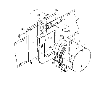
Fig. 1 illustrates a main portion of a camera having a
zoom lens in which the lens system includes a cam ring 1.
The cam ring is adapted to be rotated by a driva motor 2 via
a sector gear 3 which moves front and rear lens element
groups ~not shown in the drawings) along the direction of
the optical axis. Zooming cam grooves 4 and 5 are provided
on the exterior surface of the cam ring in order to effect
zooming of the lens. Cam ring 1 is provided about its outer
(and rear) periphery with a cam surface 6 against which a
cam follower 9, provided on a lower portion of drive arm 8,
is adapted to abut. The drive arm 8 is rotatably supported
by a stationary shaft 7. Drive arm 8 is biased by spring 30
to continuously press cam follower 9 against cam surface 6
on ring 1. As best seen in Fig. 1, camming surface 6 has a
substantially curved exterior surface with a gradually
increasing height, as measured about the outer peripheral
surface of cam ring 1, sc that when cam ring 1 rotates,
drive arm 8 is rotated about shaft 7 by virtue of its
engagement with the exterior portion of cam surface 6.
A pair of left and right movable frames 31 and 32,
respectively, which are movable in directions parallel to
the direction of movement of film F, are provided in front
of the film plane along whlch the film moves. Frames 31 and
32, when taken together with upper and lower inner rails 12
(see Fig. 2) which can come into contact with upper and
lower edges of the inner face of film F, define the aperture
which, in turn, defines the image plane size.
18
Outer rails 14, which are per se known, are provided,
both above and below inner rails 12, respectivaly, in order
to bear against the upper and lower edges of a pressure
plate 10 located on a back cover of the camera (which back
cover is not shown in the draw~ngs) in order to restrict the
position of pressure plate 10. In this fashion, film F will
move along a tunnel-like passageway defined by and between
the pressure plate 10 and inner rails 12, as shown in Fig.
2.
Movable frames 31 and 32 have associated lateral plate
portions 31a and 32a, respectively, which are disposed
oppositely to each other and which are provided with racks
17 and 18, respectively. These racks have teeth which are
engaged by a s~ngle common pinion 16 located between lateral
plate portions 31a and 32a. With such a gearing
arrangement, movable frames 31 and 32 can latsrally move, in
opposite directions, perpendicular ~o the optical axis,
while maintaining a symmetrical positional relationship
between them. Movable frame 31 includes a generally
cylindrical pro;ection 21 which is engaged within Y-shaped
fork or recess 20 on the upper end of drive arm 8, so that
as the drive arm rotates about shaft 7, movable frames 31
and 32 will laterally move as a result of the movement of
projection 21 on frame portion 31a. In other words, the
pivoting motion of the drive arm translates into oscillating
motion of projection 21 and causes relative movement of
frames 31 and 32 in equal distances and irl opposite
dlrections
Cam surface 6 is shaped so that the ~xit pupil in the
zoom lens system will be located at its forwardmost
position, and at its most distant location from film F, when
cam follower 9 of drive arm 8 contacts the lowest end 6a of
cam surface 6. As in the position of Fig. 1, the exit pupil
will be located at its rearmost position, closest to film F,
when cam follower 9 contacts the highest end 6b o~ cam
surface 6.
19
With such an arrangement, when cam ring 1 is rotated
for zooming, drive arm 8 will rotate in accordance with the
shape of cam surface 6 which abuts cam follower 9 so as to
move movable frames 31 and 32 rightwardly and leftwardly,
respectively, with respect to the optical axis of the
camera; the movable frames will be moved in opposite
directions over the same displacement. The angular
displacement of drive arm 8 about stationary shaft 7 in the
clockwise direction, as viswed in Fig. l, will be larger
when the exit pupil is closest to film F, so that movable
frames 31 and 32 will be most closely located to each other
in this position. To the contrary, angular dlsplacement of
drive arm 8 will be the smallest when the exit pupil is
farthest away from film F, so that movable frames 31 and 32
will then be brought lnto their largest spaced position.
Thus, the size of the actual image plane can always be
controlled within predetermined limits by properly designing
the shape of camming surface 6.
Fig. 3 illustrates the positional relationship between
the exit pupil and movable frames 31 and 32 by providing one
example thereof. In ~ig. 3, S represents the closest
position of the exit pupil, i.e., a position in which the
lens system comes closest to film F, and L represents the
farthest position of the exit pupil, in which the lens
system is located farthest from ~ilm F. Assuming for a
moment that the exit pupil is in position S, the pupil will
have an exit pupil radius rS, with the image plane size
being defin2d by the ray of light cS. When the exit pupil
is in position L, the Pxit pupil will have an exit pupil
radius rL and the imaga plane size will be defined by a ray
of light cL. Accordingly, it will be necessary to move
movable frames 31 and 32 into positions designated by tha
solid line (when the exit pupil is in position S) and the
dotted line (when the exit pupil is in position L), in order
to make the actual image plane size de~ined by the ray o~
light cS identical to the actual image plane size defined by
` ` ~ 3 ~
the ray of light cL, irrespective of the change in position
and radius of the exit pupil, respectively.
It should be appreciated that in practice it is not
necessary to strictly control the movement of movable frames
31 and 32 in order to always establish a precisely identical
lmage plane size, since the image plane size can have a
predetermined tolerance which lies in a range in accordance
with predetermined standards, as illustrated in Fig. 17.
The curved profi]e of camming surface 6 has been shown
in an exaggerated fashion in Fig. 1 for the purpose of
clarifying and best illustrating the principles of movement
of the cam ring 1 and the drive arm 8, which has a cam
follower 9 abutting cam surface ~.
It should also be noted that the present invention is
not directed to the particular lens system which is used,
and, accordingly, the details of the lens system used for
varying the focal length in response to rotation of the cam
ring 1 are not illustrated in the drawings.
Second, third and fourth embodiments of the present
invention will now be described in detail; each of these
embodiments is intended to control image plane si2e, as
described above.
In order to achieve a substantially complete flatness
for the film, in the second, third and fourth embodiments,
an aperture ~rame 120 (as shown in Fig. 6) is provided which
is capable o~ approaching and moving away from the f~lm
plane F along the optical axis of the camera lens. The
aperture frame is adapted to approach the ~ilm when the film
is completely wound, in order to form a tunnel shaped gap or
space for the film to traverse between khe frame and the
pressure plate, and to move away from tha film both during
winding and rewinding of the film.
Figs. 4-7 illustrate the second embodiment of the
present invention, in which the aperture frame is actuated
by an electromagnetic actuating means. Aperture frame 120
is provided in front of pressure plate 10, which pressure
. I . .. ... . . . . ... . .
21 ~3~ 2
plate is per se known, as shown ln F~g. 18, and is adapted
to move in two directions along the optical axls oE the
imaging lens system of the camera. Aperture frame 120 i5
generally rectangular and include~ a flat surface 120a
located opposite to ~ilm F. Aperture frame 120 also
include~ a central aperture 12Ob which corresponds to the
standard image plane size determ~ned, e.g., by JIS.
Aperture frame 120 is provided, along its lower
opposite end, with right and left guide plates 122, only one
of which is illustrated in Figs. 4 and 5. The guide plates
are substantially identical, and eac~ includes a guide slot
124 which extends in a direction perpendicular to the plane
of the film. The guide slot ~ncludes a forward end 124a
which serves, via its selec~ive engagement with pin 126, to
limit rearward movement of the frame into a position closely
adjacent to the film plane. A p~n/slot engaged position is
shown in Fig. 4. Guide pins 126, which are provided on
camera body B, are engaged i.n the respective guide slots
124, so that aperture frame 120 can be moved in a direction
perpendicular to the fllm plane while maintaining the
parallel relat10nship between flat surface 120a of the
aperture frame and the film plane. Springs 128, one of
which is illustrated in F~gs. 4 and 5, are provided between
each guide plate 122 and camera body s; these springs
are adapted to continuously bias the aperture frame
120 towards film F.
Iron members or pieces 130 are attached to the front
ends oE each guide plate 122 and are located opposite from
3~ electromagnets 132, which are provided in the front of the
guide plates. The electromagnets 132 form, together with
-the attractive iron members 130, an electromagnetic actuating
means. Electromagnets 132 are energized to attract
corresponding iron pieces 130 in order to move aperture
frame 120 away from film F, tllereby overcoming the biasing
force~of spring 128, as shown in Fig.5. The electromagnets
22
132 are activated ~s described herein~f-ter. ~ig.7 is
timing cllart illustrating the rel~tionship between the
operation of electrom~gnets 132, a camer~ release button
or switch (illustrated schematically), and a winding motor
(again illustrated schematically) Eor winding film F. Both
the winding motor and release button are well known and
are not illustrated in detail because their d~tails do no-t
form a portion of the present invention.
As seen in Fig. 7, when the release button is pushed, a
release signal is turned to its ON position, so that
releasing will be effected. When the r~leasing operation is
completed, i.e., when the release signal is turned to OFF,
electromagnets 132 and the f~lm winding motor will be
actuated. When the film winding ~otor and the
electromagnets 132 are turned ON, iron pieces 130 of
aperture frame 120 will be attracted by energized
electromagnets 132, so that aperture frame 120 will move
away from film F. In this state, in which aperture Erame
120 is located away from the film, the film will be wound
over one frame by the film winding motor. When film F is
wound by one frame, a film windlng completion signal is
issued, so that the winding motor and electromagnets 132
will be deenergized. As a result of this deenergization,
aperture frame 120 will be returned to its initial position
in which the aperture frame is moved into a position closely
adjacent to film F via the action of return springs 128.
The above operation is repeated until the picture on
the last film frame has been taken. When no film frames
remain to be taken, a signal representing the end of the
film is issued so as to energize electromagnets 132; iron
pieces 130 of the aperture frame 120 will again be attracted
by electromagnets 132 in order to further separate or space
aperture frame 120 away from film F. Simultaneously, the
film wlnding motor will be energized to reverse and thereby
rewind film F.
when rewinding of the film terminates, a signal
~ 3
23
repres~nting compl~tion of film rewindiny is issued, and
electromagnets 132 and the film winding motor are thus
deenergized.
In accordance with this second embodiment o~ the
present invention, upon releasing, aperture frame 120 will
closely approach film F in order to restrict the image plane
size and to form a tunnel-shaped traversing path for ~ilm F
between pressure plate lo and the frame, thus improvin~ the
flatness of the film ~. When film F is being wound and
rewound, aperture frame 120 will be moved away îrom fllm F
under the influence of electromagnets 132, and, accordingly,
the film emulsion layer will not be damaged. Additionally,
resistance to movement of film F will be decreased by such
movement, resulting in a dec:rease in power consumption which
need to be supplied from the motor.
Although the entire aperture frame approaches and moves
away from the film in the embodiment which is illustrated,
it is also possible to move only a portion of the aperture
frame, e.g., only right and/or :Left edge areas of the
aperture frame which could be formecl as separate portions of
the aperture frame would then need to 3~e moved away from a
ma;or portion of the aperture frame. rrhi~ is true in cases
ln which the image plane size in the vertical direction is
restricted by the inner rails which have been discussed
previously.
Figs. 8~11 illustrate a third embodiment of the present
invention, in which the aperture frame is mechanically
actuated by a mechanical actuating means rather than by an
electromagnetic actuating means, as in Figs. 4-7.
Aperture frame 120 is generally rectangular, with a
shape similar to that of the aperture frame in the second
embodiment, and includes a front lower right edge flange
220a and a front lower left edge flange 220a/ as illustrated
in Figs. 8 and 9. Flanges 220a will come into abutment with
6tepped ~portions 120c formed on camera body B in order to
limit th~ po~ition of the aperture frame 120 in which it is
` ` 24
most clesely ad~acent to film F. Aperture frame 120
includes a flat surface 120a located opposite from film F
and an aperture 12Ob which corresponds to a predetermined
standard image plane size in accordance wlth the JIS.
An aperture frame actuating plate 222 is attached to a
front lower and of aperture frame 120 via right and left
hand springs 224, as shown in Fig. ~i~ Actuating plate 222
is provided with an elongated slot 222a which extends in a
direction perpendicular to the optical axis of the camera
and which i5 adapted to be associated with a film winding
and rewinding mechanism.
One embodiment of a film winding and rewinding
mechanism, and its associated connecting mechanism, wlll
hereinafter be described. Pinion gear 230 is connected to a
drive shaft (not shown) on a drive motor (also not shown)
and is adapted to mesh wikh an entire gear 232a of a double
gear 232 which is rotatably supportçd on camera body B.
Double gear 232 comprises a complete gear 232a, which
includes teeth about its entire outer periphery, and a
partial gear 232b, which has a diameter smaller than the
diameter of complete gear 232a, and which includes teeth
only along a portion of the outer periphery of partial gear
232b.
Double ~ear 232 is attached to a switching lever 234
which is coaxlal with the gear and which is rotatable
relative to double gear 232 to switch between film winding
and rewinding operations. Switching lever 234 is provided,
along a free end thereof, with a planetary gear 236 which is
rotatably supported by switching lever 234 and which meshes
with the complete gear 232a of double gear 232. Switching
lever 234 reverseg the directions of its swinging motions in
accordance with the directions of rotation of double gear
232.
The partial gear 232b of double gear 232 can be engaged
by a spool gear 238 which iB connected to a spool 240 for
winding the film via a friction membe,r (not shown in the
;
~ 3 ~
drawings). Spool gear 238 meshes with sprocket driving gear
242, having sprockets 244, via an intermediate gear 244a.
These gears are formed so that when double gear 232 rotates
by one turn, the film will be wound by one frame.
Planetary gear 236 selectively meshes with an aperture
frame driving gear 246 or a first film rewinding gear 250 of
a film rewinding gear train in accordance wikh rotation
caused by the swinging movement of switching lever 234.
lo Speci~ically, when pinion gear 230 rotates in a clockwise
direction, as shown in Fig. 8, in order to e~fect a winding
operation, switching lever 234 Will rotate in a
counterclockwise direction, so that planetary gear 236 will
come into engagement with aperture frame driving gear 240.
To the contrary, when the pinion gear rotates in a
countercloc}cwise direction, as illustrated in Flg. g, in
order to effect a rewinding operation, switching lever 234
will rotate in a clockwise direction, so that planetary gear
236 will come into engagement with flrst rewinding gear 250.
Aperture frame drlving gear 246 includes an eccentric
driving pin 248 which is ~itted within elongated slot 222a
of a respective actuating plate 222. The first film
rewinding gear 250 is engaged by a film rewinding gear 256
which is integrally attached to a ~`ilm rewinding shaft (not
illustrated) via gears 252 and 254 o~ the gear train.
Figs. llA, ~lB, llC and llD illustrate operation of the
apparatus of Figs. 8-lo. In each of these Figs., neither
switching lever 234 nor planetary gear 236 are illustrated,
and only one spring 224 is shownl in order to clarify
explanation of the operation of this device.
Upon completing preparation for taking a photograph,
i.e., when the film has been completely wound by one ~rame,
aperture frame driviny gear 246 will stop at a dead polnt,
at which point driving pin 2 48 Will most closely approach
pressure plate 10, as illustrated both in Figs. 8 and llA.
In this position, springs 224 are compressed, and,
accordingly, aperture frame 120 will come into abutment with
26
stepped portions 120c of camera body B at flanges 120a of
aperture frame 120, such that the rear face of aperture
frame 120 will closely approach film F. Accordingly, the
image plane will be strictly restricted by the aperture of
aperture frame 120, which moves into a positio~ closely
adjacent to film F. Specifically, frame 120 and plate 10
are spaced so as to form a tunnel-shaped gap or space within
which the film will he guided for movement. Furthermore, in
this position, spool gear 238 will face a toothless portion
of partial gear 232b, along which no teeth are provided.
When the release button is pushed to effect a releasing
operation, the motor rotates in order to rotate pinion gear
230 in a clockwise direction. Rotation of pinion gear 230
in this clockwise direction causes the complete gear 232a,
which meshes with pinion gear 230, to rotate. As a result
of this rotatlon, doubl.e gear 232 rotates, and the rotation
of complete gear 232a is transmitted to aperture frame
driving gear 246 via planetary geax 236, so that driving pin
248, and, accordingly, aperture frame actuating plate 222,
will separate or become spaced from pressure plate 10. This
causes further separation of aperture frame 120, which is
connected to aperture frame actuating plate 222 via spring
224, away from film F, thereby permitting film to travel
freely during unwindtng and rewindlng.
On the other hand, since spool gear 238 is located
opposite the toothless portion of partial gear 232b, the
spool gear will not rotate for a certain period of time
after the motor begins rotation, i.e., until it engages the
teeth on the partial gear. When aperture frame 120 moves
completely away from film F, the toothed portion of partial
gear 232b will engage spool gear 238 to rotate the spool
gear, as illustrated in Fig. llB. As a result of such
engagement, film F will be wound, as shown in Fig. llC, by
spool 2~0.
When the toothless portion of partial gear 232b is
again located opposite from spool gear ,238, the film winding
27 ~3~ 'J
operation will end, so khat spool gear 23~ will stop its
rotation, as shown in Fiy. llD. In this position, the motor
will continue rotation in order to rotate aperture frame
actuating gear 246. Each time the aperture frame actuatiny
gear 246 rotates by one turn, i.e., when all the components
are positioned as illustrated in Fig. 3, the motor will stop
and the film winding will terminate. The release operation
will be effected in the position illustrated in Fig. 8, and
when this releasing operation ends, all of the above-noted
operations will be repeated.
Rewinding of the film is carried out as will now be
hereinafter described. When the end of a roll of film F is
detected (by a conventional fi].m sensor), the ~llm rewinding
operation wlll automatically start in response to a
detection signal which is sent to the film rewinding
assembly. The motor is then reversed to rewind film F and
thus rotate pinion gear 230 in a counte,rclockwise direction,
as illustrated in Fig. 9. This reverse rotation of the
pinion gear 230 causes switching lever 234 to rotate in a
clockwise direction, so that planetary gear 236 will move
away from the aperture frame actuating gear 246 and will
come into engagement with the first rewinding gear 250. As
a result of this engagement, rotation of the first rewinding
gear 250 is transmitted to gear 256 via the gear train
(including gears 252 and 254) to effect rewinding o film F.
When the end of the film is detected prior to the
rewinding operation of film F, the film will stop moving in
any stage of the winding operation (in a position between
that shown in Figs. llB and llC), such that the film will ~e
placed under tension. After this stage, film rewinding will
begin while aperture frame 120 moves away ~rom film F.
Further, when the operation is swltched to the rewinding
stage, planetary geax 236 will move away from aperture frame
actuating gear 246, so that the aperture frame actuating
gear 246 will not rotate. Accordingly, there is no
possibility that aperture frame 120 will come into contact
~ 3 ~
28
with the emulsion layer of film F during winding or
rewinding, and will therefore not result in damage to the
film emulsion layer.
Although in the embodiment which is illustrated
aperture frame 120 is entirely movable away from and towards
film F, it is also possible to move only right and left hand
edges of the aperture Erame, which may be formed as separate
parts from the remaining body portion, in cases in which the
image plane size, in the vertical direction, is otherwisa
restricted by the presence of the upper and lower inner
rails.
Figs. 12-16 illustrate the Eourth embodiment of the
present invention, in which the aperture frame i6 actuated
by a combination of an electromagnetic ackuator as
illustrated in the second embodiment of the invention and a
mechanical actuator as illustrated in the third embodiment
of the invention. ~ ,
In the fourth embodiment, the aperture frame 120 is
again generally rectangular in configuration, similar to the
other embodiments of the invention. The aperture frame is
continuously biased away from film F by springs 322l which
are positioned between the camera body and the aperture
frame. The farthest position of aperture frame 120 from
film F is limited by a stop 324 provided on the camera body.
Aperture frame 120 includes a charging pin 326 which is
adapted to bear against a charging cam 342.
Pinion gear 330, which is secured to a drive shaft on a
drive motor (neither of which is illustrated in the
drawings) meshes with planetary gear 332, which is rotatably
supported by shaft 334 of the camera body. The shaft
includes a generally V-shaped, bent switching lever 336
which is rotatably supported and which has an intermediate
gear 338 attached to a shaft at an intermediate portion of
the lever. Intermediate gear 338 then engages a first
planeta~ry gear 332. A second planetary gear 340 is
rotatably mounted on the Eront end of the switching lever
29 ~ `3~
and is adapted to be engaged by intermediate gear 338. In
this manner, the switching lever will selectively swing in
clockwise and counterclockwise directions, in aacordance
5 with the directions of rotation of planetary gear 332. As a
result, intermedlate gear 33~ wlll move away Erom and close
to a sprocket drive gear 346 having sprock2ts 348 integrally
attached thereto, in accordance with the direction of
swinging motion of switching lever 336. Charging cam 342 is
10 integrally attached to planetary gear 340, and has a curved
profile, as illustrated best in Figs. 12 and 13. Pinion
gear 330 also engages a spool gear 344, which is
frictionally engaged by a spool (not illustrated in the
drawings).
A first rewinding gear 350 is provided on the camera
body and is adapted to selectively engage and move away from
sun gear 340, in accordance with the selected swinging
motion of switching lever 336; and the camera is also
provided with rotatable gears 352 and 354, which transmit
rotation of firsk rewinding gear 350 to rewinding gear 356,
which includes a film rewinding shaft 356a integrally
attached thereto.
With such an arrangement, when pinion gear 330 rokates
in a counterclockwise direction, as illustrated in Fig. 12,
switching lever 336 will rotate in a clockwise direction in
order to bring intermediate gear 338 lnto engagement wlth
sprocket drive gear 346 BO as to rotate sprocket 348, in
order that the film will be wouncl by the sprocket.
To the contrary, when pinion gear 330 rotates in a
clockwise direction, as illustrated in Fig. 13, swltching
lever 336 will rotate about shaft 334 in a counterclockwise
direction, so that the planetary gear 340 will come into
engagement with the first rewinding gear 350, such that
rewinding shaft 356a will rotate in order to wind film F.
Behind and below apertura frame 120 a restriction
mechanism for the aperture frame is provided, as best shown
in Figs. 14 and 15. This restriction assembly ~s adapted to
30 ~L3~
retain aperture frame 120 in a photographing positlon in
which the aperture frame is moved inko a position closely
ad~acent to film F, agai.nst the bias oE spring 322. The
res-tria-tion assembly has a restriction lever 362 which is
pivotably connected to the bottom of the camera body. Lever
362 inaludes a hook 362a a~ its fron~ end which is adjaaent
to aper-ture frame 120, and an attraatirlg member 362b at its
rear end, opposite to the front end. The attraation piece
362b is located opposlte to an eleatromagnet 360.
Restriation lever 362 is aontinuously biased by springs 364
such that hook 362a will come into abutment with the front
face of aperture frame 120. Inner hook sùrfaces 362c, as
shown in Figs. 14 and 15, are provided to engage the ront
frame surface and maintain frame 120 in a position alosely
adjacent to film F, forming a tunnel-shaped gap, between
the plate and the frame. Ih other words, hooks 362a and
surfaces 362c serve to maintain frame 120 close to, but
spaced from, the film plane of film F. Electromagnet 360
20. will attract, when activated, attractive piece 362b so
as to rotate restrlction levre 362 against the bias of spring
364. l'his rotation, as sllown in Figure 15, will cause hook
362a to move downwardly to free frame 120 -to'move, under
tl~e influence of spring 322, into abutment with stop 324.
The operation of ths apparatus of the fourth em~odiment
of the invention will now be described, particularly with
respect to Figs. 16A-16D.
~ig. 16A illustrates the position of the apparatus in
which the releasing oparatlon terminates and a winding
30 operation begins, similar to that of Fig. 12. In this
position, the restrict~on lever 362 is disengaged from
aperture frame 12~, so that the aperture frame will separate
from film ~ under the asslskance or bias of spring 322, and
so that intermediate gear 338 will mesh with sprocket drive
35 gear 346.
When the winding operation is lnitiated, pinion gear
3 1 ~ 3 ~ 9 ~
330 will rotate in a counterclockwise direction, such that
planetary gear 340 will rotate in a clockwise direction,
and, accordingly, charging cam 342, which is integrally
attached to planetary gear 340, will rotate in the same
direction. Rotation of aharging cam 342 will cause charging
pin 326, which bears against the cam surface of charging cam
342, to move upwardly as shown in Fig. 16A, so as to move
aperture frame 120 towards film F and against spring 322, as
lo shown in Fig. 16B.
Further rotation of charging cam 342 will cause
charging pin 326 to move into abutment with the largest cam
lobe portion 342a of charging cam 342, so that aperture
frame 120 will closely approach film F. As a result, hook
362a of restriction lever 362, which is biased by spring 364
in a counterclockwise direction as shown in Fig. 14, will
come into engagement with aperture frame 120 in order to
prevent the aperture frame from moving away from film F
(under the bias of spring 322), as shown in Fig. 16C.
Further rotation of charging cam 342 causes the largest
cam lobe portion to move away from charging pin 326 so that
the smallest diameter portion 342b of the charging cam which
is connected to the largest cam lobe portion 342a via a
stepped portion will be positioned oppositely from charging
pin 326, as shown in Fig. 16D. This will result in
completion of the winding operation of film F. In this
position, charging pin 326 cannot move to the smallest
diameter portion 342b of the charging cam 342, insofar as
aperturs frame 120 is retained in a position in which the
aperture frame is closely adjacent to film F, as a result of
the action of restriction lever 362 which bears against
aperture frame 120.
When a releasing operation is effected, i.e., when the
apparatus is ln the position illustrated in Fig. 16D,
electromagnet 360 will be energized when tha releasing
operation is completed in order to attract attractive piece
362b of restriction lever 362 and in order to separate hook
32 ~ 3 ~ ~ a~ ~
362a from aperture frame 120. As a result of this movement,
aperture frame. 120 is released from restriction lever 362,
and, accordingly, the aperture frame will quickly move into
a position in which it contacts stop 324 under the force of
spring 322. Specifically, the aperture frame will move
further away from film F and move into the position
illustrated in Fig. 16A. After this movement, the previous
operations will be repeated.
When the end of the film is detected by a sensor (not
shown), the rewinding operation will begin. The motor will
reverse to rotate the pinion gear in the clockwise
direction, so that planetary gear 332 will rotate in the
counterclockwise direction. Simultaneously, sw.ltching lever
336 will rotate in a countercloc~wise direction in order to
separate intermediate gear 338 from sprocket drive gear 344,
so that the planet gear 330 will mesh with first rewinding
gear 350. ~s a result of this meshing, rotation of pinion
gear 330 will be transmitted to rewinding gear 356, and the
rewinding shaft will rotate in order to rewind ~ilm F.
Normally, the rewinding operation begins by performing
one frame winding operation, during which time aperture
frame 120 moves away from film F and charging cam 342 moves
away from charging pin 326 in response to rotation of
switching lever 336, prior to establishing engagement
between planetary gear 340 and first rewinding gear 350.
Accordingly, no rewinding o~ the film occurs during periods
when aperture frame 120 is spaced closely with respect to
film F.
It is possible that the operation will be switched to
a rewinding operation immediately prior to completion of the
winding operation, when restriction lever 362 restricts the
motion of aperture frame 120, as illustrated in Fig. 16C.
In such case, possible damage to the film is avoided by
activating electromagnet 360 to further space aperture frame
120 from film F in accordance with rotation of switching
lever 336.
i
~ 3 ~ 2
Further, in the fourth embodiment, it is possible
to move only right and left edge portions of the aper-
ture frame, which are formed as independent elements,
separately from the remaining portion of the aperture
frame, as in the second and third embodiments of the
invention, independently away from and towards film F.
This could be done in any case in which the vertical
size of the film plane is restricted by the inner rails.
Reference will now be made to Figs. 17 to 19 which
lo illustrate prior art.
Fig. 17 illustrates the enlargement of the image
plane in the lateral direction. In Fig. 17, Q repre-
sents the aperture defining surface, R represents the
aperture formed in the aperture defining surface Q, and
F represents the film plane. The actual image plane
size of an image formed on film plane F, when exit pupil
E is located at position L, and the actual image plane
size of an image formed on film plane F when exit pupil
E is moved to a position S closer to film plane F than
position L, are defined by rays of light (a) and tb),
respectively. As seen in Fig 17, the actual size of the
image plane is larger than the maximum standard size
36.8 mm when exit pupil E is in a position ~ which is
closer to film plane F. There is a tendency for the
exit pupil to more closely approach film plane F when
the zoom lens increases magnification and when the size
of the lens system is minimized. Conventional fixed
apertures cannot solve this problem of enlargement of
the actual image plane which arises when the exit pupil
so closely approaches the film plane.
The film and, accordingly, film plane F, move
within a tunnel-like space defined by and between a
pressure plate 10, which ensures that the film plane
will be flat, and inner rails 12, which restrict/abut
~ 33a - ~ 3 ~
the upper and lower edges of film plate F, as shown in
Fig. 18. In Fig. 18, outer rails 14 are provided which
restrict the position of pressure plate 10, which plate
is pressed against the film via spring lOa. As seen and
understood in Fig. 18, the vertical right hand and left
hand edges of Eilm plane F are not subjected to a force
which cause the film to be pressed against pressure
plate 10. Thus, any pressing force applied to the right
and left hand side edges of film plane F is small, so
that only the right and left edges themselves of the
film plane are prevented from separating from pressure
plate 10.
Fig. 19 is a similar talbeit enlarged) representa-
tion of an image plane in the lateral direction. ~s
shown in Fig. 19, an aperture defining plane 16' is
illustrated having an aperture 17'. Film plane F' is
also shown with respect to the position of aperture
defining plane 16i. Assuming that the complete image
plane area receives 100% of the rays of light which pass
the lens system of the camera and reach the film plane
F', and that the incomplete image plane area receives
only part of the rays of light which pass through the
lens system and which reach the film plane F', when exit
pupil P' is located at position A'; and, further, assum-
ing that rays of light a' define the complete image
plane area and that rays of light b' define the incom-
plete image plane area, the actual image plane size
(i.e., the actual image plane area) can then be defined
by rays of light which correspond to a bisector of light
rays a' and bl. The actual image plane size defined by
rays of light c' can then be larger than the standard,
as noted above. This tendency, resulting from the
rearward motion of exit pupil P', i.e., towards the film
plane F', increases as the zoom lens increases magni-
fication and as the size of the lens system is mini-
~" -
~ 3 ~L ~ 3 ~
ml~ed.
~n an alternate embodiment of the present inven-
tion, which is illustrated in Figs. 20-23, film is
charged into a patrone chamher 511 and is wound by a
winding spool 513 in a winding spool chamber 512.
Between patrone chamber 511 and film winding spool
chamber 512 are provided respective pairs of upper and
lower outer rails 514 and inner rails 515, respectively,
having the front elevational shapes which are illus-
lo trated in Fig. 20. Specifically, outer rails 514 are
adapted to contact a pressure plate (not illustrated in
Fig. 20) on the back cover of a camera in order to
- restrict and define the position of outer rails 514.
Inner rails 515 are adapted -to abut the upper and lower
edges of a front face or emulsion surface of the film.
The distance between outer rails 514 and inner rails
515, as measured along the optical axis direction, is
usually about 0.2 mm. As a result, a tunnel-like space
or gap is formed between the inner rails and the pres-
sure plate. The film is adapted to move in the tunnel-
like space created between the pressure plate and rails
514 and 515. Upper and lower inner rails 515 define the
upper and lower edges of aperture defining plane 516.
Plane 516 includes a central opening 517 which assists
in defining the image plane size on film positioned in
the camera.
According to one main feature of this embodiment,
the right and left-hand peripheral edge portions of the
aperture frame which defines aperture 517 are inclined
so as to project towards inner rails 515. Fig. 23
illustrates an enlarged view of a portion of aperture
517. Projections 51
.,
34 ~ 3~
are provided along right-hand and left-hand edges of the
aperture deEining plane 516 of aperture frame 550, which
define aperture 517. Since projections 518 determine the
image plane size along both the right and left hand sides,
width(s) of the projections (see Fig. 23) 518 is as small as
possible, so that there will be no substantial change in the
size of the image plane. Projections 518 are smoothly and
continuously connected to aperture defining plane 516 via
inclined surfaces 551. The projecting length of projections
518 from aperture defining plane 516 can be determined in
accordance with the position and size of the exit pupil when
the zoom lens system moves illtO its rearmost position. ~he
projecting length of projections 518 towards inner rails 515
will now be illustrated by way of a specific example.
In Fig. 23, the position or positions of the exit pupil
when the zoom lens system comes closest to the film, and
when the lens system is moved farthest away from the film,
respectively, have been assumed to be represented by S
(closest) and L (farthest), respectively. The actual slzes
of the image plane when the exit pupil is located at the
positions S and L are defined by rays o~ light aS and cL,
respectively. The radii of the exit pupil at positions S
and L are rS and rL, respectively.
The value of the distance 11 between the pro~ections
518 and ~ilm F is determined in accordance with the distance
dS or dL and ~etween the film F and position S or position
L, radius rS or rL of the exit pupil, and aperture size Ap,
in order to satisfy the requirement of the JIS.
As one example, when dS = 20.2 mm, dL = 49.25 mm, rS =
0.79 mm, r~ = 3.6 mm, and Ap - 35.9 ~ 36.0 mm, the distance
11 will be calculated as follows: 11 = 0.~4 ~ 0.14 mm. In
vie.w of the irregularity of the dimensions of the portions
of die cast camera bodies, influences on the emulsion layers
o~ film, and the irregularity in lens systems, if Ap = 35.9
mm and 11 = 0.35 mm, the sizes of the image plane at
positions S and L will be 36.52 mm and 36.16 mm,
1 3 ~
- 35 -
respectively. These values will be wlthin the standard
values of the JIS.
When the values mentioned above are selected, e.gO,
~ the 35 mm film (which usually has a thickness of 0.12
0.16 mm) which has the relatively large resilient char-
acteristics discussed above when the film has directly
emerged from patrone chamber 11 and is moving into the
relatively larger space or gap defined between inner
rails 515 and aperture defining plane 516, there will
accordingly be no possibility that the film will contact
aperture defining plane 516. On the other hand, when
the film closely approaches aperture 517, the flatness
of the film will be increased by outer rails 14, e.g.,
by their engagement with the pressure plate, and by
inner rails 515. The film will pass through the narrow
space or gap between inner rails 515 and projections
518, while maintaining the film in a relatively largely
flat position. This will prevent the emulsion layer of
the film from contacting projections 51~ and since this
ensures that the film is in an area adjacent to projec-
tions 518 ~i.e., near the periphery of aperture 517),
the image plane size along the right and left-hand
directions will become stabilized, regardless of the
position of the exit pupil of the lens system.
As should be understood from the foregoing dis-
cussion, in accordance with the present invention, even
when the exit pupil approaches the rearmost position,
the image plane size along the left and right-hand
directions should be maintainable within a predetermined
standard.
Industrial Applicability
The apparatus of the present invention can be app-
lied to any camera having a zoom lens in which the image
plane size can be varied in accordance with the posi-
tional displacement of an exit pupil of the lens in
order to restrict the image plane size within predeter-
mined limits, and in order to take a properly sized
photograph; the embodiments of the invention need not
necessarily be used
:~ 3 ~ 2
36
with a ~oom lens, however.
It is obvious to those o~ ordinary skill in the art
that the above embodiments have been described as speci~ic
representative examples o~ the present invention, and that
other features and embodiments within the scope of the
claims would be within the s]cill of those o~ ordinary skill
in the art to which this invention pertains.