Note: Descriptions are shown in the official language in which they were submitted.
131~80
The invention relates to a system for monitoring the closing
of a movable barrier mounted on a frame surrounding an
opening and movable back and forth relative thereto between
an open state and a closed state, with a first circuit
provided outside of the movable barrier for the purpose of
emitting a signal indicating the closed state.
~ystems of this kind are needed chiefly in vehicles, e.g., in
streetcars, trains or subways, to make sure that when doors
have to be operated by remote control from a central point,
such as a driver's cab, they are fully closed. Usually the
barriers or doors in question are single-leaf sliding doors
or doors having two leaves which can slide against one
another, which can be driven back and forth in separate
frames around the door openings of the passenger compartments
be electrical, pneumatic or other actuators. Nevertheless,
other kinds of doors may be involved, such as folding doors
or swinging doors, as well as other movable barriers such as
windows, flaps, sliding valves or the like. [For the sake of
simplicity, however, the word "door" will be ~sed herein to
refer to all kinds of such movable barrier~
X
1319180
The door states which are to be siynalled are especially the
"open" state or "closed" state, and the state of being free
to close. This is to be understood to mean that a door is
able to close or is in the "free" state if it can be moved to
a closed position by the actuator. On the other hand, a door
is not closable or is in the "blocked" state when some
obstacle, such as a passenger, a ~ox or the like, is blocking
the opening and the door therefore cannot be fully closed by
operating its actuator.
The states of "open" or "closed" are usually monitored by
means of electromechanical limit switches which are actuated
when the doors approach their closed positions. These limit
switches are disposed on the frame and connected to circuits
which emit a signal identifying the "open" or "closedl' state
and thus indicate the state of the door to the driver of a
vehicle or produce a controlling signal. The circuits are
disposed outside of the doors, i.e., they are mounted not on
the latter but on the frame or other part of the vehicle or
the like and therefore are stationary, in contrast to the
doors, and can be moved only together with the vehicle or the
like.
X 2
131ql80
The presence of an obstruction in the opening might be
indicated by monitoring that period of time which is started
in the closing operation by actuating the door driver. If
one of the signals from the limit switches identifying the
"closed" state does not arrive within a predetermined period
of time after the actuation of the driver, this signifies
that the door in question is in the "blocked" state on
account of an obstruction.
Since such systems are often considlered to be insufficiently
safe, they can have, in addition to the limit switches, a
switching means contained within the door itself which
responds when the door encounters an obstruction and thereby
supplies additional "free" or "blocked" signals which
indicate an obstruction or trigger a controlling operation
immediately without any predetermined waiting period.
One problem with such means of detection lies in their
sensitivity to trouble and hence their insufficient
reliability in operation. Their limit switches are subject
to considerable mechanical wear, and in extreme cases their
position in relation to the doors can change, which would
falsify the "open" and "closed" signals. Furthermore, the
switch means mounted on the doors themselves are connected to
the circuits and indicators mounted outside of the doors by
trailing electrical or pneumatic lines which are undesirable
~ 3
1 3 1 9 1 80
for safety reasons. Syskems of this Xind therefore require
careful maintenance that has to be performed repeatedly at
frequent intervals of time.
The invention provides a system of the kind described above
such that the signals necessary for the indication o~ the
closing operation and of the state of the door which are
produced in the door itself are without contact, i.e.,
without mechanical contact by physical components and without
galvanic connections between the doors and the circuits
provided outside of the doors.
In accordance with the invention the first circuit has at
least one first inductive element mounted on the frame and a
second electrical circuit having at least one second
inductive element is mounted on the door and, for the purpose
of the contactless production of the signal indicating the
closed state in the first circuit, is inductively coupled
with the first inductive element in at least one selected
position of the door.
The invention brings with it the advantage that the door-
state signals are produced contactlessly by inductive
2~
131q'180
coupling. Mechanical wear and undesired changes of the
position of switches or the like are therefore
impossible, so that, even with a low frequency of
maintenance, a high safety of operation is achieved. The
signals "closed" and "open" or "blocked" and "free" can
thus be produced with a single second circuit which upon
the occurrence of the "blocked" signal simultaneously
excludes the emission of the "closed" signal, so that,
even if very small obstructions should jam between the
door and the frame, the two signals cannot occur
simultaneously. The system in accordance with the
invention can easily be so arranged that trouble in the
system, such as power failures, burst lines, short-
circuits or the like, will always result in a signalling
of the "open" and/or "blocked" state. This has the
advantage, especially when the system is used on
vehicles, that in the event of trouble in the system
there will be no possibility of giving a wrong signal
that the vehicle is ready to start.
In one aspect the invention provides a system for
monitoring the closing state of a movable barrier which
is mounted on a frame defining an opening and is movable
between an open and a closed position, said system
comprising: first electric circuit means mounted on said
barrier for being moved therewith and including first
inductive means; and second electric circuit means
mounted outside said barrier and including second
inductive means and an oscillator means for producing, if
switched on, an electric current in said second circuit
means; said first and second inductive means being
arranged with respect to each other in such way that, if
said oscillator means is switched on, said second
inductive means is enabled to contactlessly induce
electric energy in said first inductive means for --
activating said first electric circuit means, and said
~ 1~
;~
1 3 1 q 1 80
first inductive means is enabled to contactlessly induce
an electric signal characteristic of a closure state of
said barrier in second inductive means in at least one
selected position of said barrier.
The invention will now be further explained by means of
embodiments in conjunction with the appended drawing,
5a
13191~0
wherein:
Figures 1 and 2 diagrammatically show a system in accordance
with the invention for indicating a state of a door which is
characterized by an obstruction in the door opening, showing
the door in the open ~tate and in the obstructed state,
respectively.
Figures 3 and 4 diagrammatically represent a system in
accordance with the invantion for verifying the closed state
of a door, showing the door open and fully closed,
respectively.
Figures 5 to 7 are schematic diagrams o~ electrical circuits
for the systems of Figures 1 to ~.
Figure 8 is a schematic diagram of an alternative embodiment
of the second circuit of the system of Figures 3 and 4.
Figure 9 is a diagrammatic representation of the application
of a system according to the invention to a vehicle door.
Figures 10 and 11 are an enlarged front view and top view of
details of three inductive elements of the system according
to Figure 9.
:30
1319180
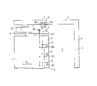
Figure 1 shows diagrammatically a movable barrier 1, e.g., a
sliding door which can be moved back and forth in the
direction of an arrow _ bPtween its open position in Fig. 1
and its closed position which is nearly reached in Fig 2. The
door 1 in this case is mounted for displacement in a manner
not shown in detail in a frame or the like defining an
opening 2. This frame contains, for example, a frame member
3 parallel to the direction of movement, and a frame member 4
pexpendicular thereto, which contains on its inside a margin
5 against which an edge 6 of the cloor 1 will abut when the
door is in the closed position. The abutment edge 6 is, for
example, cushioned by a gasket 7 of an elastic material
extending o~er the entire height of the door 1. The gasket
is preferably hollow throughout its length and its interior
is provided with a plurality of switches 8 spaced parallel to
the edge 6. These switches 8 consist, for example, of
momentary contact or pressure switches with movable contacts
~a, 8b, 8c etc., which are held in the normally open position
by a spring or the like and face the abutment edge 6. If a
local pressure is applied to the abutment edge 6 in the area
of any of the switches 8, thereby pressing th~ gasket 7
inwardly, at least one of the movable contacts 8a, b, c will
close the corresponding switch 8. All switches 8 together
form a switch system 9.
~ 7
1 31 9 1 ~0
At the upper end, in Fig. 1 the door 1 has a bar 10 which is
disposed closely parallel to the frame member 3. The bar 10
is moved back and forth together with the door 1, extends
preferably oYer its entire width, and can be covered~
cladding.
An inductive element 12 acting as a sender is mounted on the
frame member 3, and consists of a conductor loop (Fig. 1)
with a section parallel to the direction of movement; or a
corresponding coil with several turns of wire in a circuit 13
in Fig. 5, which consists preferably of the element 12 and an
oscillator 14 connected to its terminals, which produces an
alternating current of, e.g., 100 kHz. When the oscillator
14 is turned on a high-frequency alternating electromagnetic
field develops in the inductive element 12.
second inductive element 15 is affixed to bar lC and
extends best over its entire length, and it too can consist
of a conductor loop (Fig. 1) and a section parallel to the
direction of movement or a corresponding coil tFig. 5) with
several turns of wire, and forms together with a condenser 16
connected in series an additional electrical circuit 17 in
the form of a resonant circuit. Without any physical contact
between them, the two inductive elements 15 are arranged on
~ 8
1 3 1 9 1 80
the frame member 3 and bar 10 so that the said sections are
inductively coupled to one another regardless of the position
of the door 1 i.e., both in the open and closed positions of
the door and in all possible positions in between, as
indicated schematically in Fig. 1 ~y a closed loop 18. So
that the coupling factor will be the same in all positions,
the length of the section of the indu~tive element 15, is at
least equal to the length of the possible movement of the
door 1, while the corresponding section of element 12 should
have a comparatively small length iand be coupled with an
equal portion of element 15 in any position of the door 1.
The snergizing of the oscillator 14 (Fig. 5) will thus result
in contactless induction of an alternating current in the
inductive element 15. At the same time the capacity of the
condenser 16 is preferably made such that this alternating
current will be maximum under the given circumstances, i.e.,
the reactive component of the impedance of the inductive
elemsnt 15 will be just compensated by that of the condenser
16.
The circuit 17 furthermore contains two conductors 19 and 20
which are connected to both terminals of the condenser 16 and
are laid in the door 1. Conductor 19 is connected to one
side of each of the switches 8 and line 20 to the other side
of same. As a result, either the two conductors 19 and 20
connected to the condenser 16 are interrupted if all switches
X 9
1 3 1 9 1 80
8 are in their open position, as in Fig. 1, or, as in Fig. 2,
the condenser 16 is by-passed or short-circuited whenever at
least one switch 8 is closed. This will happen for example,
if upon the closing of the door 1 an obstruction 21 indicated
diagrammatically in Fig. 2, is in the opening 2 and is wedged
between the edge 5 and the abutment edge 6, so that the door
1 possibly cannot be completely closed and at least a gap 22
remains in the opening 2. Since the closing causes at least
one of the switches 8 to short-circuit the condenser 16, the
capacitive portion of the reactive component of the impedance
of circuit 17 is in this case eliminated, thereby reducing
the alternating current, which originally was great when
oscillator 14 was turned on, to a comparatively low level.
In Figs. 1 and 2, an additional inductive element acting as a
receiver is affixed to frame member 3; like element 12, this
element 12 can consist of a conductor loop (Fig. 1 with a
section parallel to the direction of movement, or a
corresponding coil with several turns of wire, and is
connected into an additional electrical circuit 25 provided
outside of the door 1. The elements 15 and 24, without any
physical contact with one another, are affixed to the bar 10
and to frame member 3 in such positions that their said
sections are coupled inductively to one another regardless of
the position of the door 1, i.e., both when th~ latter is
~ 10
1 31 q 1 80
open and when it is closed, as well as in all possible
intermediate positions, as i~ indicated diagrammatically in
Fig. 1 by a loop 26. So that the coupling factor will be the
same in all positions, the physical relationship of t~e
elements 15 and 24 will be substantially the same as ~he
physical relationship of elements 12 and 15. Thus, when the
oscillator 14 is turned on ~Fig. 5), a flow of current will
be induced contactlessly in every position of the daor, and
its magnitude will depend on the magnitude of the alternating
current flowing in circuit 17, and thus on whether all
switches 8 are open or at least one switch 8 is closed.
Otherwise the elements 12 and 24 are physically mounted on
frame member 3 such that their direct inductive couplin~ will
be as small as possible.
In Fig. 6, circuit 25 contains two conductors 27 and 28
connected to the ends of element 24, and connected each
through a diode 29, 30, to the two terminals of a relay 31.
Furthermore, the output of an additional diode 32 is
connected to the output of diode 29, while its input is
connected to the output of diode 30, and the input of diode
29 is applied to the output of a fourth diode 33 whose input
is connected to the input of diode 30, so that the four
diodes 29, 30, and 32, 33, form a bridge rectifier in a
conventional Graetz circuit for the alternating current
induced in circuit 25. Parallel to the element 24 is a
X 11
131~180
condenser 34 which with element 24 forms a parallel resonant
circuit, and parallel to the relay 31 there is provided an
additional condenser 34 which acts as a smoothing condenser
for the alternating current rectified by the bridge -
rectifier. The relay 31 furthermore acts on the movingcontact of a switch 36 which is normally open. This switch
36 is connected together with an additional circuit 37 in a
circuit 38, not further represented, which turns on and off a
drive 39, also not further represented, for the automatic
opening and closing of the door 1. Switch 37 is at the same
time to represent the switch which is actuated whenever the
command "open" and~or "close" is to be given for the door.
The manner of operation of the system shown in Figs. 1, 2, 5
and 6 is as follows:
In the energized operating state, i.e., especially when the
oscillator 14 (Fig. 5) is turned on, a voltage of
predetermined magnitude is induced in element 15 through the
inductive element 12, regardless of the position of the door
1. As a result, an alternating current of predetermined
magnitude is also induced in element 24 and is independent of
the position o~ the door 1. This alternating current is of
such a level that the relay closes the switch 36 normally
held open by a spring or the like. This prepares the circuit
38, so that actuation of switch 37 can start up the drive 39.
Circuit 25 thus gives a signal corresponding to the "free"
state.
~ 12
1 3 1 q 1 80
The door 1 is now pushed to the open or closed position until
a limit switch yet to be described responds. If, however,
during a closing movement an obstruction (e.g. 21 in Fig. 2)
is in the opening 2, this obstacle will cause at least one of
the switches 8 normally in the open state to close, thereby
bypassing the condenser 16 of circuit 17. As a result, the
current in circuit 17 is considerably reduced and there~ore
no longer suffices to induce in the inductive element 24 a
voltage sufficient to cause relay 31 to respond.
Consequently, switch 36 opens, thereby interrupting circuit
38 and stopping the drive 39. The door 1 therefore comes to
a stop as soon as an obstacle is caught between the door 1
and the edge 5. The response sensitivity depends, among
other things, on the elastic properties of the gasket 7, the
closing force of switch 8, the force exerted by drive 39 on
the door 1, and the pressure that is exerted by the obstacle
21 on the gasket 7. The arrangement is best made such that
the total pressure per unit area exerted on the gasket 7 in
the closed state will not suffice to shift the switch system
9 to the state in which it will signal an obstruction.
Figs. 3 and 4 show a system similar in principle to the
system in Figs. 1 and 2, equal parts being identified by the
same reference number.
X 13
1 3 1 q 1 ~0
A circuit 42 mounted on the door 1 contains in this case not
only the condenser 1 and the inductive element 15 fastened to
the bar 10, but also an additional inductive element 43 which
consists of a conductor loop or a coil with several turns of
wire, is connected in series with element 15, and like the
latter is moved back and forth with the door 1. Element 43
forms with element 15 and the condenser 16 a resonant circuit
in which the condenser 16 again serves to keep the reactive
component of the impedance low or t:o compensate it, so that
when oscillator 14 (Fig. 5) is turned on a high alternating
current flows in circuit 42. Element 43 of preferably
arranged physically so that it will have, insofar as
possible, no direct inductive coupling with the two elements
12 and 15, its axis being represented perpendicular to the
axes of elements 12 and 15 for this purpose. Element 24 in
Figs. 1 and 2 is furthermore replaced with an inductive
element 44 acting as a receiver which is disposed on the
frame member 3. At the same time the relative arrangement of
the inductive elements 43 and 44 is made such that a strong
inductive coupling exists between them only when the door is
in the closed position shown in Fig. 4.
~5
1 31 9 1 80
In Fig. 7 the inductive element 44 is wired in a circuit 45
disposed outside of the door 1 and has two conductors 46 and
47 connected to the ends of element 44, which are connected
to the two terminals of a relay 48. Otherwise circui-t 45
contains, like circuit 25 in Fig. 6, the four diodes 29, 30,
and 32, 33 forming a bridge rectifier, as well as the two
condensers 34 and 35. Relay 48 acts on a switch 49 normally
held open by a spring or the like, which is in series with a
diagrammatically indicated battery 50 and a pilot light 51.
The manner of operation of the system seen in Figs. 3, 4, 5
and 7 is as follows:
In the energized operating state, i.e., especially when the
oscillator 14 is turned on (Fig. 5), a current of
predetermined magnitude is induced in circuit 42 through
element 1~, independently of the position of the door 1.
This current also flows through element 43, but remains
ineffective as long as the door is in the open position or an
only partially closed position, because in these positions
there is no sufficient inductive coupling between the
elements 43 and 44. Consequently, the alternating current
induced in circuit 45 in theses positions is very low or nil,
so that the current flowing through the relay 48 is not
sufficient to close switch 49. If, however, the abutment
edge of the door 1 engages the edge 5 of the frame
X 15
13191~0
member 4 after the door is closed, then the great inductive
coupling desired and established by their physical position
in relation to one another will result in a voltage in
element 44 which will cause relay 48 to respond.
Consequently switch 49 is closed and the pilot lamp 51 will
light, signaling the closing of the door 1. Circuit 45 in
this case emits a signal indicating the "closed" state.
~lternatively, element 44 could be replaced by an element
mounted on frame member 4, which would be coupled inductively
with sufficient strength in the closed state with an
inductive element corresponding the element 43 and mounted at
the right end of the bar 10. The arrangement represented is
especially desirable when the door is one leaf of a two-leaf
vehicle door or the like, whose both leaves are moved against
one another to close the door and which abut against one
another at their longitudinal edges when closed.
The two systems for monitoring the closing of the door 1,
which are represented separately in Figs. l, 2 and fi on the
one hand and Figs. 3, 4 and 7 on the other, can also be
combined in a simple manner, for example by providing circuit
17 in Figs. 1 and 2 with an additional inductive element
corresponding to inductive element 43 in Figs. 3 and 4 and
using accordingly two circuits according to Figs. 6
~ 16
131~180
and 7. The manner of operation is then the same, with the
additional advantage that, when one of the switches 8
responds (Figs. 1, 2~ in no case can switch 49 (Fig. 7) ke
actuated thereby erroneously giving the signal "closed", even
if the obstruction 21 (Fig. 2) is very thin and consists only
of a finger or the like. This is because when one of the
switches 8 responds, the condenser 16 (Figs. 1, 2) is
bypassed and thus the current flowing through elements 15 and
43 is made very low, and the voltage that is induced in
circuit 45 will not suffice to close switch 49 even if the
door 1 has reached the closed position except for the small
gap 22 (Fig. 2) and therefore the inductive coupling between
the elements 43 and 44 is already quite great.
Furthermore, as indicated diagrammatically in Fig. 8, the
circuit 42 according to Figs. 3, 4 and 7 could be replaced by
a circuit 53 which includes only element 15 and the condenser
16 in series, and in which two additional inductive elements
54 and 5~ are provided which are connected in series with an
additional condenser 56. In this case the one inductive
element 54 would be constantly coupled with the inductive
element 15 while the other inductive element 55 would assume
the function of elemen-t 43 in Fig. 7. In this embodiment the
current necessary for indicating the closed state of the door
1 is likewise contextless coupled by inductive element 12 to
the circuit mounted on the door 1 and transferred by the
X 17
1319180
latter to an additional circuit in accordance with the state
that is to be indicated.
All embodiments described in connection with Figs. 1-to 8
have it in common that they have a first circuit 25 or 4
situated outside of the door 1 for issuing a signal
indicating the closed state, this Eirst circuit having at
least one first inductive element 24 and 44, respectively.
Furthermore, a second circuit 17, 42, and 53, respectively,
with at least one second inductive element 15, 43, 54, 55, is
mounted on the door l, and is inductively coupled with the
first element in at least one position (Figs. 3, 4 and 8) or
also in all positions of the door l (Figs. 1 and 2) in order
thereby to produce contactlessly in the first circuit the
signal identifying the state of closure of the door.
Furthermore, a third circuit 13 with a third inductive
element 12 is provided preferably at a point situated outside
of the door, which serves to couple contactlessly to the
second circuit the electrical energy necessary to indicate
the state of the door. In all variants the advantages are
furthermore obtained that in the second circuit only the
energy necessary for door-state indication needs to be
coupled and that when a short-circuit, a line break, a power
failure or any other trouble occurs in the system, the
"closed" signal can never be given, which is important
~ 18
131~180
especially for the use of the described systems as door
monitors on streetcars, railroads or subway trains and other
such vehicles.
The switches 8 can be any desired capacitive, piezoelectric
or other such switching means, or even photoelectric cells or
the like, which can assume at least two states, and normally
are in the one state, and when an obstruction is caught
between the door 1 and the frame member 4 ~or a second door),
are shifted to the other state in order thereby to produce a
current different from the normal in the second circuit. It
is furthermore possible to construct the inductive elements
represented schematically as coils as single or multiple
large-area conductor loops which can also be given a figure-
eight geometrical configuration.
A practical embodiment of the invention is represented inFig. 9 in conjunction with a diagrammatically indicated
passenger compartment 58 of a streetcar~ train or subway car.
A door 60 displaceably mounted in a frame 59 strikes in its
closed state against a frame member 61 or a second door leaf
mounted for displacement in the contrary direction. The door
60 is provided on its abutment side with a resiliently
yielding gasket 62 which has an internal cavity 63 throuyh
its entire length. In this cavity is a switch system 64
which consists of two resiliently flexible bare contact
~ 19
131ql80
strips made from an electrically conductive material, which
extend preferably also over the entire length of the gasket
62 and are connected at their ends to the two terminalæ of a
condenser 65, while their other encls are free. Normally, the
contact strips are nowhere in contact with one another, ~o
that the condenser 65 acts as a capacitive element o~
preselected magnitude. If, however, a hand 66, for example,
is caught in the gap between the door 60 and the frame member
61, the gasket 62 yields resiliently at this point, causing
the contact strips to flex resiliently and come in contact
with one another, as indicated in Fig. 9 by a broken line 67,
so that the condenser 65 is short-circuited. The two contact
strips thus have the same effect as a plurality of individual
switches 8 disposed closely one above the other as indicated
in Figs. 1 and 2.
In Fig. 9 the condenser 65 is connected in a circuit 68 which
is mounted on a bar 69 fastened to the door 60, and connected
to the two terminals of an inductive element 70 which
consists of a conductor loop with two parallel coils of an
electrically conductive wire or the like which are
substantially congruent with one another and disposed in a
rectangular shape. Two additional inductive elements 71 and
72 consists of a ferrite core 73 and 74, each in the form of
a slotted ring on which a number of turns 75 and 76 of an
electrically conductive wire or the like are wound. The
l3lslsn
ferrite cores 73 and 74 surround a section of element 70
running parallel to the direction of movement of the door 60,
this section being substantially perpendicular to the central
planes of the ferri~e ~ores 73 and 74, and running
approximately through their central axes. The ends of the
winding 75 are connected to the conductors 27 and 28 ~f Fig.
6 and the ends of the winding 76 a:re connected, for example,
to the oscillator 14 in Fig. 5. When the oscillator 14 is
turned on~ therefore, an electromagnetic alternating field is
produced by element 72 and induces an alternating current in
the section surrounded by it and thus in the entire element
70. This current produces a magnetic alternating field
(right-hand rule) concentrically surrounding the conductors
of element 70, and this field in turn passes through the
ferrite core 73 and results in an induced current in the
winding 75 of element 71. The physical arrangement and
manner o~ operation are to this extent the same as in the
system according to Figs. 1 and 2.
In Figs. g to 71 an additional inductive element 77 is
disposed inside of the left end of the element 70, and acts
like element 43 in Fig. 7 and element 54 in Fig. 8. Element
77 consists of a loop of two conductors shaped in the manner
of a flat figure eight, whose portions are substantially
rectilinear and whose central plane substantially ~oincides
with the central plane of element 70. As seen in Figs. 10
X 21
1 3 1 q 1 80
and 11, in which the elements 71 and 72 have been omitted for
the sake of simplicity, if element 77 is in the working
state, for example on the side marked with a solid line 78,
over the magnetic field which is produced by the current
flowing through the element 70, it is inductively coupled
with element 70, so that a current also flows in element 77.
The reactive component of its impedance can be compensated by
a condenser 79. The current in element 77 results in the
magnetic field indicated schematically by circular arrows for
half a period, which is strongest on both sides of the center
part of the figure-eight conductor loop, because four
sections of conductor situated parallel side by side have
current flowing through them, while on the two sides only two
sections of conductor are present. In Fig. 10 these four
sections of conductor are partially covered by an inductive
element 80 whose construction is to be seen particularly in
Fig. 11, while the conductors of elements 70 and 77 are
represented in section as usual.
The detection of the magnetic field produced by element 77 is
performed by inductive element 80, which is in the form of a
U-shaped ferrite core 81 on which a coil 82 is wound; its
action is the same as that of element 44 in Figs. 3 and 4.
Element 80 is fastened to the frame 59, while element 77 is
mounted like element 70 on the bar 69 such that, when the
door 60 is closed, it assumes precisely the symmetrical
X 22
131ql8()
center position seen in Fig. 11, closely beneath the element
80 in which the two pole faces of the ferrite core 81 are
substantially parallel to the central plane of element 77 and
precisely aligned with the two halves of the figure eight
loop, so that the ferrite core 81 has maximum permeation. In
the closed state, this produces a maximum signal in element
80, while slight shifts of the door produce a highly
unsymmetrical positioning of element 80 relative to element
77 and hence they produce a substantially weaker induced
signal. When door 60 is open, element 80 assumes
approximately the position 80a represented in Fig. 10, in
which there is virtually no inductive coupling with element
77. The manner of operation is therefore the same as in
Figs. 3 and 4 and Fig. 8. An advantage of the arrangement
according to Figs. 10 and 11 is that the elements 77 and 80
can be very small in size, so that a closely limited
threshold value can be established for the switching signal
and thus the closed position can be established within narrow
limits.
The invention is not limited to the embodiments described,
which can be modifi~d in many ways. Especially the
arrangement and configuration of the various inductive
elements and circuits can be adapted to the particular
application and therefore can differ from Figs. 1 to 11. It
is also possible to combine the functions of various
X 23
13191~0
inductive elements in a single inductive element and a single
circuit. For example/ inductive element 12 can be placed in
a circuit which on the one hand supplies electrical energy
for circuit 17 and on the other hand acts on a positioning
element and thus makes it possible to recognize the current
state of the switch system 9 or of the door. In such an
embodiment, therefore, one of the elements 12 or 24 could be
omitted.
X 24