Note: Descriptions are shown in the official language in which they were submitted.
1~19808
The present inventlon relates to a method for
sterillzlng laminated packaglng material for forming a
packlng contalner to preserve a llquld such as juice or
milk contained therein for a long period of time. More
particularly, the present lnvention relates to a method
for sterilizlng a packaging material obtained by forming
an elongated hollow packaging material including a paper
layer therein into a sleeve having a predetermined
length.
There are two conventional methods for sterilizing
packing containers.
According to the first conventional method, a
sheet-like continuous laminated packaging material
including a paper layer is sterilized with a hydrogen
peroxide (H2O2) sclution, and the hydrogen peroxide
solution is dried and removed with hot air or the like.
The sheet-like packaging material sterilized by this
method is formed into a tube, and one end of the tube is
then sealed. A predetermined liquid is poured in the
tube, and a portion below the llquid surface is sealed.
The resultant packaging material containing the liquid
therein is cut at predetermined positions, thereby
obtaining individual containers each containing the
liquid.
According to the second conventional method, a
sterilized laminated continuous packaging material
is cut into blanks each having a predetermined length.
~k
13~8~8
-- 2
A container having an openlng and a predetermined shape
ls formed from each blank. A hydrogen peroxide solution
ls sprayed inside the container to sterilize its inner
surface. The container ls heated and dried with hot air
to remove the hydrogen peroxide solution. A liquid is
then poured in the container, and the container is
sealed, thereby finishing a container filled with a
liquid.
According to the first conventional method, it is
easy to sterilize the packaging material. In addition,
sterilization, drying, filling of a liquid, sealing
below the liquid surface, and cutting are performed in
the order to seal the liquid in the container. Even if
a packaging material is a laminated material including a
paper layer, the liquid contained in the container is
not adversely affected by cut end faces and paper dust
produced by cutting. In addition, there is no head
space for air left inside the container and collected at
the top portion of the container. Therefore, the first
conventional method is advantageous in long-term preser-
vation. Furthermore, the first conventional method is
advantageous in that no hydrogen peroxide is left at a
folded portion since the sealed packaging material is
folded at predetermined positions to form individual
containers.
The shape of the packing containers manufactured by
the first conventional method is limited to a brick-like
1319808
shape since the llquid is poured in the tube-like
packaging material and the packaging material is sealed
and formed into a predetermined shape. Since the indi-
vidual containers are obtained after the liquid is
sealed in the tube-like container material, the
packaging material must be flexible. Therefore, it is
difficult to form the packing container by a rigid
material. For this reason, when a large amount of
liquid is filled in a large packaging material, each
individual container is deformed by the weight of the
liquid. Therefore, the first conventional method is not
sultable for manufacturing large containers.
Since each individual container is formed by
sealing the packaging material below the surface of
liquid contained in the packaging material, a head space
which is disadvantageous in food preservation can be
elimlnated. However, there is a fear for spilling of
the contained liquid at the time of opening the
container. When the container is used for a liquid con-
taining a solid substance such as ~uice or soup, thesolid substance may be trapped at the sealed portion,
thus causing incomplete sealing.
According to the second conventional method, a con-
tainer having a predetermined length is sterilized and
then a liquid is filled therein. Even if a liquid
containing a solid substance is filled therein, there is
no fear of trapping of the solid substance at the
_ 4 _ 1319808
sealing portion. In addition, a head space is assured,
and the liquid is not split when the container is
opened.
According to the second conventional method,
s however, since the elongated continuous packaging mate-
rial is cut into blanks each having a predetermined
length and a container is formed from each blank, paper
dust is produced during cutting of the packaging mate-
rial into the blanks. In addition, nonsterilized end
faces are formed. During formation of an empty
container by folding the packaging material, the paper
dust may be trapped at the folded portion. In addition,
the nonsterilized end face is exposed ins~de the
container at the folded portion. For this reason, it is
dlfficult to maintain the packing container in a perfect
aseptic state. The packing container sterilized by the
second conventional method is not suitable for preserv-
ing the liquld for a long period of time.
In a columnar container formed from a rectangular
blank and having a gable-like upper portion and a flat
bottom portion, cut end faces are not exposed inside the
container. For this purpose, one edge of the blank ls
bent outward, and the folded portion is sealed on the
inner surface of the other edge. In this container, a
step is formed on the inner surface, and the hydrogen
peroxide solution serving as a sterilizing agent tends
to be left at the step portion.
1319808
The present invention provides a method of sterllizing
a packag]ng material formed such that a Laminated packaging
material inc~lding a paper layer is cut into blanks each
having a predetermined length, each blank is bent to form an
empty container, a liquid is filled in the empty container,
and the container with the liquid is sealed.
The present invention also provides a method of
sterilizing a sleeve-like packing material, which iq free
from a danger caused by a residual sterilizing agent.
Accordingly, the present invention provides a method
for sterilizing liquid packaging blanks, comprising the
stepq of:
providing liquid packaging blanks which are made of a
laminated material including a paper layer, and each of
which has two open ends and an axis;
sterilizing the liquid packaging blanks by dipping the
liquid packaging blanks sequentially in a sterilizing agent
while inc~ining the axes of the liquid packaging blanks with
respect to a horizontal plane;
removing sterilizing agent from the liquid packaging
blanks by blowing sterilized and compressed air at the
liquid packaging blanks; and
drying each of said liquid packaging blanks by blowing
hot air at the liquid packaging blanks at least in one
direction along the axes thereof.
In a further aspect, the present invention provides a
method for sterilizing liquid packaging blanks, comprising
the steps of:
.. " ~
13198~8
- 5a -
providing liquid packaging blanks whlch are made of a
laminated material including a paper layer, and each of
which has two open ends and an axis;
sterilizing the liquid packaging blanks by dipping the
llquid packaging blanks sequentially in a sterilizing agent
while inclining the axes of the liquid packaging blanks with
respect to a horizontal plane;
washing off the sterilizing agent attached to the
liquid packaging blanks by dipping each of the blanks in a
waQhing solution; and
removing the washing solution by blowing sterilized and
compressed air at the washed blanks;
said washing step including a process of maintaining a
content of the sterilizing agent in the washing solution
less than 1.0 wt%.
~Ai~
- 6 - 1319808
This lnventlon can be more fully understood from
the following detailed descrlption when taken in con-
~unctlon wlth the accompanylng drawings, in which:
Fig. 1 ls a perspectlve view showing the overall
sterilizing apparatus used in a method of the present
invention;
Fig. 2 is a sectional view showing an arrangement
of the sterilizing apparatus shown ln Fig. l;
Fig. 3A ls a front vlew showlng a circulating
unit for holding blanks;
Fig. 3B is a side view of the unit shown in
Fig. 3A;
Fig. 4 is an exploded perspective view showing part
of the circulating unit of the sterilizing apparatus
shown in Fig. l;
Fig. 5 is a side view showing part of Flg. 4;
Flg. 6 is a perspectlve vlew showlng the relation-
shlp between a washing station and a sterllizlng agent
removal station;
Fig. 7 ls a perspectlve vlew showlng a flnished
beverage contalner sterlllzed by the sterlllzlng appara-
tus;
Fig. 8 is a perspective view showing a lower por-
tion of the beverage container shown in Fig. 7;
Fig. 9 is a perspective view showing an upper por-
tion of the beverage container shown in Fig. 7;
Fig. 10 is a sectional view showing a sterilizing
~ 7 ~ 13198~8
apparatus suitable for continuously sterilizing
packaglng materials; and
Fig. 11 is a sectional view showing a modification
of the sterilizing apparatus shown in Fig. 10.
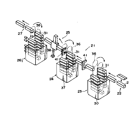
Figs. 1 and 2 show a sterilizing apparatus used in
a sterilizing method according to an embodlment of the
present invention. This sterilizing apparatus is used
in an aseptic packing machine for packing a gable top
container 1 shown in Fig. 7.
A sterilizing apparatus 21 is entirely housed in an
aseptic chamber. Hollow columnar blanks 2 having two
open ends are supplied from a supply station 22 located
on the right side in Fig. 1. Each blank 2 is sterilized
by a sterilizing station 23, washed in a washing station
24, and subjected to removal of the sterilizing agent in
a sterilizlng agent removal station 25, and dried by
first and second hot air drying stations 261 and 262.
The dried blank ls transferred to the next process from
a dellvery station 27.
In the supply station 22, a large number of blanks
2 are folded flat and are stacked on an appropriate sup-
port. The flat blanks 2 are sequentially chucked by
means of suction cups (not shown) and expanded into
hollow columnar blanks. Fig. 2 shows an air cylinder 28
for operating these suction cups. Each hollow columnar
blank 2 is fed to the sterilizing station 23 by a
lateral feed chain 29a having lateral grippers.
13198~8
The sterllizing station 23 includes a sterilizing
tank 30 which stores a 35 wt% hydrogen peroxide solution
as a sterilizing solution heated to, e.g., about 80C,
and an endless circulating unit 31 which circulates the
blanks 2 while holding them in the lateral direction.
The circulatlng unit 31 is best illustrated in
Figs. 3A, 3B, 4, and 5. For example, a plurality of
link plates are coupled to form two parallel endless
chains, and holdlng members 32 are attached to the outer
travel surface of the chalns through llnks 31a. Refer-
ence numerals 51 and 52 denote chains, respectively.
The holding member 32 comprlses four guide ralls 33 each
having an L-shaped section to gulde edges of the blank 2
and a pair of brackets 34 for fixing the guide rails 33.
Holes 34a and 34b formed in the pair of brackets 34
receive a fixing pin or a bolt (not shown) to fix the
brackets to the links 31a of the chains. These holes
34a and 34b are formed to cause the holding member 32 to
hold the blank 2 at an inclination angle of 2 to 5O with
respect to the horizontal axls when the holding member
32 ls flxed on the correspondlng mountlng llnks 31a.
The gulde rails 33 of the the holdlng member 32 are
flared at the right inlet portion, as shown in Fig. 4,
so as to cause the lateral feed chain 29a to smoothly
feed the blank.
When the clrculatlng unlt 31 ls lntermlttently
rotated by appropriate drive sprockets 36 mounted on
9 1319808
a drive shaft 35 arranged above the sterilizing tank 30
in a direction indicated by an arrow in Fig. 1, the
blanks 2 are sequentlally dipped ln the sterilizing
solution in the sterilizing tank 30 and sequentially
removed therefrom. Since each blank 2 has two open ends
and is dipped in the sterilizing solution while the
blank 2 is incllned with respect to the horizontal axis,
the sterilizing solution can perfectly reach the inner
surface of the blank 2. Therefore, nonuniform
sterilization upon attachment of bubbles or the like can
be prevented. In addition, when the blank 2 is removed
from the sterilizing solution, the sterilizing solution
flows from the inside of the blank, and the sterilizing
solution left inside the blank can be reduced.
The sterilized blanks 2 are fed to the washing sta-
tion 24 by lateral feed chains 29b and 29c through the
installed guide rails 33.
A washing tank 37 which stores a washing solution
is disposed in the washing station, as shown in Figs. 1
and 2. When a circulating unit 31 for causing a holding
member to hold each blank 2 in an inclined state in the
same manner as in the sterilizing station 23 is lnter-
mittently rotated by the drive shaft 35 and sprockets
36, the blanks 2 are sequentially dipped in a washing
solution in the washing tank 37 and are removed
therefrom. The sterillzing solution attached to the
surface of each blank 2 flows together with the washing
lO- 131980~
solution.
Aseptlc water filtered through an aseptic filter is
stored ln the washing tank 37 ln a predetermlned amount.
Thls aseptlc water may be heated to 60C to 80C to
S thoroughly remove the sterilizing solution.
The blanks 2 from which the sterilizing solution is
washed in the washing station 24 is fed to the steriliz-
ing agent removal station 2s through a lateral feed
chain 29d while the circulating unit 31 is kept stopped.
The height of the blank 2 at the inlet position of the
washing station 24 is preferably changed from that at
the outlet position of the washing station 24 to prevent
the sterilizing agent from being mixed in the subsequent
station. An aseptic water nozzle may be arranged to
spray aseptic water to the lateral feed chain 29d to
wash off the sterilizing solution attached to the
lateral feed chain, thereby minimizing entrance of the
sterillzing solutlon lnto the subsequent station.
As shown in Figs. 1 and 2, the sterilizing removal
station 25, in lllustrated embodiment, comprlses four
radlal mandrels 38 at equal angular intervals. In thls
case, the blanks 2 are mounted on the four radial
mandrels 38. The mandrels 38 are intermittently turned
in synchronism with the operation of the circulating
unit 31 of the washing station 24 along a plane parallel
to a lower travel surface of the circulating unit 31.
At a stop position, the mandrel 38 located nearest to
1319808
-- 11
the washing station 24 is inclined downward with respect
to the horlzontal plane. The distal end portion of this
mandrel 38 is matched wlth the outlet of the washing
station 24, thereby facilitating mounting of the blank
2.
As best shown in Fig. 6, the mandrel 38 has a rec-
tangular distal end 39. The blank 2 mounted from the
dlstal end 39 is held by peripheral guide rails 40.
An aseptic air nozzle 38a is continuously opened on
the periphery of the dlstal end 39. Therefore, when the
blank 2 grlpped by grippers 41 of the lateral feed chain
29d is mounted on one of the mandrel 38, the sterilizing
solution droplets are scattered from the inside of the
blank 2 with air flushed from the aseptic air nozzle
38a.
In this embodiment, as shown in Fig. 1, nozzle
units 41 having the same structure as described above
are arranged between the sterilizing station 23 and the
washlng station 24 and between the washing station 24
and the sterilizing agent removal station 25 to flush
the aseptic air to the outer surface of the blank 2,
thereby removing the sterilizing solution from the outer
surface of the blank 2.
The nozzle unit 41 comprises a C-shaped 3-side
nozzle 41a, one side of which is open not to interfere
movement of the lateral feed chain 29d and a rod-like
one-side nozzle 41b located at a position corresponding
1319808
- 12 -
to the opening of the C-shaped 3-side nozzle 41a, as
shown in Fig. 6. These nozzles 41a and 41b are fixed at
predetermined posltlons of the apparatus by supports 42a
and 42b, respectlvely. Aseptic air is flushed from
nozzle ports 42a and 42b continuously open in the inner
surfaces of the nozzles 41a and 41b, so that the
sterilizing solution is removed from the outer surface
of the blank.
The sterilizing solution is removed from the outer
surface of each blank 2 by means of the nozzle unlt sl
and the lnner surface thereof by means of the sterlllz-
lng agent removal statlon 25. The resultant blanks 2
are fed to the first hot air drying station 261 by a
lateral feed chain 29e. In the hot air drylng statlon
261, the blanks 2 are clrculated in a hot alr drylng
tank 43 by a clrculatlng unit 31 having the same
arrangement as those ln the sterilizing station 23 and
the washlng statlon 24. Hot alr supplled from air
supply plpes 44 is blowed from one opening to the other
openlng of each blank 2 through hot air nozzles 45
arranged along a travel path of the circulating unit 31,
thereby drying the blanks. A detector 46 ls arranged ln
the drylng tank 43 to detect an amount of hydrogen
peroxlde solution contained in the air in the tank.
Whether the sterilizing solution is effectively removed
in a path up to the sterilizing agent removal station 26
is determined by a detection signal from the detector
- 13 - 1319808
46. The circulating unit 31 may circulate within the
drylng tank 43 in the flrst hot air drying station 26
such that the blanks 2 are held horizontally.
Each blank 2 blown with hot air from one opening to
the other opening thereof in the first hot air drying
station 261 is fed to the second hot air drying station
262 by a lateral feed chain 29f. The blanks 2 are moved
by a circulating unit 31 in the same manner as ln the
first hot air dry station 261. Hot air is blowed from
the other opening to one opening of each blank 2, so
that the blank is dried again.
The dried blanks 2 are then fed from the blank
dellvery statlon 27 to the next statlon by a lateral
feed chaln 25g.
The clrculatlng unlts 31 ln the sterlllzlng statlon
23, the washing statlon 24, and the drylng statlons 261
and 262 are lntermlttently drlven by the drlve shaft 35.
The mandrels 38 of the sterllizing agent removal station
25 and the respectlve lateral feed chains are driven in
synchronism with the operation of the drive shaft 35.
Thus, transfer of the blanks 2 from one statlon to
another station can be smoothly performed.
Accordlng to the sterllizing method of the above
embodiment, the blanks 2 are entirely dipped in the H22
solution and perfectly sterilized. The sterlllzing
solution is washed off while the blanks are circulated
in the washing tank 37. when the blanks are mounted on
- 14 - 1319808
the mandrels 38 in an inclined state, the sterillzing
solution left on the lnner surfaces of the blanks 2 are
scattered by alr sprayed from the aseptlc alr flushed
nozzle 38a. At the same tlme, aseptlc air ls flushed to
the outer surface of each blank 2 by the nozzle unit 41
arranged between the washing station 24 and the steri-
lizing agent removal station 25. Therefore, the steri-
lizing solutlon attached to the lnner and outer surfaces
of the blanks 2 can be removed by the behavlor of alr
and a gravltational effect. The blanks 2 can be
inclined even ln the sterlllzlng tank 30 or can be
washed wlth hot water (washing water) of 60C to 80C
after sterilizatlon, thereby further enhanclng the
sterlllzatlon effect for the blanks 2. Since hot alr ls
blowed from one openlng to the other openlng of each
hollow blank 2 having two open ends in the hot alr
drylng tank 43 ln the first hot air drying station 261
and is dried, and then hot air ls blowed from the other
openlng to one openlng of each blank 2 in the hot alr
drying tank 43 in the second drying station 262 to dry
lt again, perfect drylng wlth hot alr can be achieved.
The blanks 2 can be perfectly sterilized, and the sterl-
lizing agent can be completely removed therefrom. For
thls reason, the resultant contalner is free from danger
when a beverage ls filled therein.
Blank samples each having a size of 70 x 70 x
300 mm were dipped in a 35 wt% H22 solution at 80C for
- lS - 1319808
10 seconds. The sterilized blank samples were washed,
sub~ected to sterillzing solution removal, and drled
~lS seconds) ln condltlons shown in Table 1, and whether
the concentration of residual H22 was reduced below
SO ppb as a target value was examined. Test results are
shown in Table 1.
- 16 ~ 1 3 19 8 0
Table 1
Sam- I II III IV V VI
Ple ( C) ~%) (kqf/cm2) ( C) ( C) ( C)
A 28 0 5 150 _
B 40 0 5 150 _ 2
C 60 0 5 150 _ 0
D 80 0 5 150 150 0
E 80 0 5 150 _ 0
F _ _ 5 150 _ 8*
G _ _ 5 150 150 5*
Note: I represents Temperature of Clearlng Water;
II represent Initial ~22 Concentration in
Washing Water;
III represents Air Pressure in Mandrels;
IV represents First Drying Temperature;
V represents Second Drying Temperature;
VI represents Number of Samples Having Resldual
H22 concentratlon Exceeding 50 ppb.
Number of each sample is 16.
Alr flushing time at the mandrels ls 1.0 second.
* ... ln column VI indicates that variatlons are
found in detected residual concentratlon.
The sterlllzed blanks are conveyed in a
forming/fllllng/seallng stations for performing formlng,
fllllng, and sealing. In thls process, the bottom
- 17 - 13~9808
portlon of each blank is formed flat, ingredients are
filled from the top of the blank, and the top portion is
sealed, thereby obtaining a packing container.
According to the present invention, when an aseptic
packing container is manufactured such that a laminated
material including a paper layer is cut into blanks each
having a predetermined length, a bottom portion of each
blank is formed, and ingredients are filled ln the
blank, a continuous packaglng material made of a lamlnated
material including a paper layer is cut into sleeve-like
blanks each having a predetermined length, and the
blanks are dipped in the hydrogen peroxide. Therefore,
paper dust produced during cutting can be removed. In
additlon, the end faces of each cut blank and a folded
portlon on its lnner surface can be perfectly sterl-
lized.
After sterillzatlon, aseptlc compressed alr ls
flushed at least on the lnner surface of each blank to
remove the sterllizing solution, and therefore the
sterilizing solution can be effectively removed.
Furthermore, the blank is dlpped and sterllized in
the sterilizing solution while the blank is inclined.
Aseptic compressed air is flushed to each blank while
it is inclined, thereby effectively removing the steri-
llzing solutlon after sterllization.
After each blank is sterilized in the sterilizingsolution, it is dipped ln aseptlc water having
- 18 _ 131~808
a temperature of preferably 60C or more to wash off the
sterllizing solution. The sterilizing solution which
tends to be left ln the folded portion on the inner sur-
face of the blank can be perfectly removed.
Blank samples were dipped in a 35 wt% hydrogen
peroxide solution having a temperature of 80C for 10
seconds. The sterilized blank samples were then washed
and dried in the conditions shown in Table 2. A test of
a washing effect was performed by changing the initial
concentration of hydrogen peroxide in the washing water.
The temperature of the washing water was 60C, and the
initial hydrogen peroxide concentrations of the washing
water were changed among 0%, 0.5%, 1%, and 2%. Results
are shown in Table 2.
Table 2
Sample IIa III IV VI
(% )(Kgf/cm2 ) ( C) !N)
H 0 5 150 0
I 0.5 5 150 0
J 1.0 5 150 0
K 1.5 5 150 2
Note: IIa: represents H22 Concentration in
Washing Water;
III, IV, VI: represent condition same as
Table 1.
Number of each sample is 16.
- 19 - ~31g808
As is apparent from the above results, even if the
lnltlal hydrogen peroxlde concentration in the washing
water is not 0%, a prescribed washing effect can be
expected at a hydrogen peroxide concentration of less
than 1.0%.
In order to set the hydrogen peroxide concentration
in the washing water to be less than 1.0%, a means is
preferably provided to circulate the washing water in
the washing tank while applying ultravlolet ray to the
washlng water, or cause the washlng water to overflow
from the washing tank while washing water is kept
supplied from a washing water source at a predetermlned
flow rate.
In order to reduce an increase in hydrogen peroxide
concentration in the washing water, aseptic compressed
air is preferably flushed to each blank to remove the
hydrogen peroxlde solutlon from its surface as much as
posslble before the blank is fed to the washing station.
It ls also posslble to add acetlc acld and perace-
tlc acld to the hydrogen peroxide solution used as asterlllzlng solutlon. A typlcal composition of the mix-
ture type sterlllzlng solutlon ls as follows:
ComPonentContent (% bv weight)
Peracetlc acld 10 to 45
Acetlc acld 40 to 85
Hydrogen peroxide1 to 15
Balance (water) 1 to 15
- 20 - 13 1 9 8 08
The mixed sterilizing solution is diluted with
water and used in a concentration of 0.1 to 10.0% at 10
to 90C.
Example
Sterilization was performed by using the apparatus
shown in the drawlng. In this experiment, the sterlli-
zation was applled to cartons having both surfaces
implanted with 107 spores of Bacillus subtilis var.
golobigii [IFO 1372]. Tables A and B show the results:
Table 3
Sterilizing Concentratio Temperature No. of bacteria-
Solution (%) (C)detected carton~
H22 35 80 0
Peracetic acid
+ H22 6 60 0
ll 2 80 0
ll ll 60 3
Note: The number of cartons used was 20 for each test.
- 21 ~ 1 3 1 9 8 ~ ~
Tale 4 (Result of Residue Analysis)
Sam- I II III IV V VI VII
Ple (C) t~) (kgf/cm2) tC) (C) (C) (N)
A 28 0 0 5 150 3
B 40 0 0 5 150
C 40 0 0 5 150 150 0
D 50 0 0 5 150 0
E 60 _ _ 5 I50 6*
G _ _ _ 5 150 150 5*
Note: I represents Washing Water Temp. (C);
II represents Peracetic acid in washing water;
III represents H22 Conc. (%);
IV represents Mandrel air pressure;
V represents First Drying (C);
VI represents Second Drying (C);
VII represents No. of samples in which the resi-
dual peracetic acid and H2O2 exceeded 50 ppb.;
Air spurting ... 1.0 second
The number of samples ... n = 16
* ... Variation was found
A sterilizing apparatus shown in Fig. 10 will be
described below. This sterilizing apparatus is suitable
for sterilizing a continuous sheet-like packaging
material.
- 22 - 1319808
As shown in Fig. 10, a packaging material 80 supplied
to the sterilizing apparatus is dipped in a sterilizlng
solutlon 81 ln a sterilizing solution chamber 62 for
sterillzing the packaging material. Sterilizing time is
preferably sufficlent sterilization time, e.g., about 10
seconds. The sterilizing solution is removed from the
surfaces of the packaging material 80 passing through the
sterilizing solution 81 by a sterilizing agent removal
unit consisting of first press rollers 69 and air knives
70-
The sterilizing solution heated to about 70 to 80Cby a heater 66 in a sterilizing solution tank 61 is
supplied to the sterilizing solution chamber 62 by a
feed pump 67. A return path is open in the sterilizing
solution chamber 62 at its predetermined position
through a filter 68 for impurity removal to maintain a
constant sterillzing solution level in the sterilizing
solutlon chamber 62. Thls return path communicates with
the sterllizlng solution tank 61. Therefore, the steri-
lizlng solution kept almost at a constant temperature iskept in a constant amount in the sterilizing solution
chamber 62.
The sterilizing solution is removed from the
packaging material 80 whlch has passed through the steri-
llzing solution by the first press rollers 69 locatedabove the sterilizing solution 81 in the sterilizing
chamber and the first air knives 70 for blowing aseptic
- 23 - 1319808
air to the surfaces of the packaging material.
The packag~ng material 80 which has passed through
the sterilizlng solution chamber 62 is supplied to an
aseptic water chamber 63.
Aseptic water 82 is stored in the aseptic water
chamber 63 ~ In addltion, aseptic water spray nozzles
105 are arranged in the upper portion of the aseptic
water within the aseptic water chamber 63. The aseptic
water spray nozzles 105 are used to perfectly remove the
sterilizing solution attached to the packaging material
when removal of the sterillzlng agent by the flrst press
rollers 69 and the flrst alr knlves 70 ls lncomplete.
Aseptic water 82 ln the aseptlc water chamber 63 is
supplied from an aseptlc water tank 65 through a pump
64. Another heater 66 ls arranged in the aseptic water
tank 65. Aseptic water heated to a predetermlned tem-
perature ls supplled by a feed pump 74. In order to
malntaln a constant water level ln the aseptlc water
chamber 63, a return path is open at a predetermined
positlon ln the aseptic water chamber 63. The return
path communlcates wlth the aseptlc water tank 65 through
a three-way valve 77. Therefore, the aseptlc water
havlng almost a constant temperature ls maintained ln
the aseptic water chamber 63 in a predetermined amount.
A supply path is connected to the aseptic water tank 65
through an aseptlc water regenerating filter 79. Supply
of aseptic water to the aseptlc water tank 65 ls
- 24 - 13198~8
controlled by a control valve 78.
A pair of ultravlolet lamps 13 are arranged in the
aseptlc water chamber 63 to decompose the sterilizing
solutlon attached to the packaglng material 80 in the
aseptic water chamber 63. The sterilizing solution
introduced during a normal operatlon can be decomposed
by the lamps 13.
Units 7s and 76 for measuring sterilizing solution
concentratlons ln aseptlc water are mounted below the
aseptlc water level in the aseptlc water chamber 63.
When removal of the sterllizlng solution from the sur-
faces of the packaging material 80 cannot be performed due
to the failure of the first press rollers 69 and the
first air knives 70 or any other cause, and the sterl-
llzlng solutlon concentratlon in the aseptic water 82 isabnormally lncreased, thls state ls detected by the
sterlllzlng solution concentration measuring units 75
and 76. An abnormal detection result ls slgnaled to an
operator, and the operator swltches the three-way valve
77 to discharge water. Therefore, circulation of asep-
tic water containlng a sterillzing solution ln a con-
centratlon exceedlng an allowable level to the aseptlc
water tank 65 can be prevented. In thls case, aseptic
water of the same amount as that of discharged aseptic
water is supplied to the aseptic water tank 65 through
the control valve 78.
The packaging material 80 from which the sterilizing
- 25 - 1 3 1 98 08
agent ls washed off with the washing water in the
washlng chamber ls removed from the washing water.
The aseptic water attached to the packaging material is
removed by an aseptic water removal unit consisting of
second press rollers 71 and second air knives 72.
The packaging material 80 is then fed to a drying
chamber 64 and then the next filling/forming station.
Fig. 11 shows a modification of the sterilizing
apparatus of Fig. 10. The same reference numerals as in
Fig. 10 denote the same parts in Fig. 11, and a detailed
description thereof will be omitted.
The apparatus in Fig. 11 is substantially the same
as that of Fig. 10 except that ultrasonic oscillation
units 93 are arranged in place of the ultraviolet lamps
ln an aseptic water chamber 63. The ultrasonic oscilla-
tion units 93 can effectively remove the sterillzlng
solutlon from the packaging materlal.
The present lnventlon has been descrlbed wlth
reference to partlcular embodlments. However, the
present lnventlon ls not llmlted to these. Varlous
changes and modlflcatlons may be made wlthln the splrlt
and scope of the lnventlon.