Note: Descriptions are shown in the official language in which they were submitted.
1319979
1 TITLE OF THE INVENTION
TAPE HANDLING APPARATUS FOR RECORDING-REPRODUCTION SYSTEM
FIELD OF THE INVENTION
The present invention relates to systems for
recording signals on magnetic tape or reproducing signals
from magnetic tape, and more partlcularly to a tape handling
apparatus for use in such a system for automaticallY winding
or rewinding the magnetic tape to realize the proper
operation of the system, for example, for winding the tape
to remedy a slack occurring in the tape during rewinding.
BACKGROUND OF THE INVENTION
In recent years, more compacted video tape
recorders (VTRs) are made available. Especially, 8-mm VTRs
are realized in a greatly reduced size with a diminished
weight for use with 8-mm-wide magnetic tape.
With the development of compact and light-weight
VTRs, VTRs have been introduced into use which comprise a
camera unit and a VTR unit as an assembly. It is also
possible to realize a portable image reproduction system
which comprises a liquid-crystal television set and a VTR in
the form of an assembly. Further reduced sizes are severely
required of such VTRs.
Accordingly, VTRs are proposed which are variable
for different modes in the depthwise length along the
direction of insertion of the cassette as shown in Figs. 41
and 42 (Unexamined Japanese Patent Publication
SHO.61-271649).
The proposed VTR comprises a head cylinder ~1
having a rotary magnetic head and mounted on a main chassis
1, a reel chassis 2 provided on the main chassis 1 and
slidable toward or away from the head cylinder 11, and a
supply reel support 21 and a take-up reel support 22 which
are mounted on the reel chassis 2. The reel chassis 2 is
driven by a chassis drive mechanism (not shown) coupled to a
--1--
1319~79
l loading motor on the main chassis l.
The supply reel support 21 and the take-up reel
support 22 are drlven by a known reel support drive
mechanism having a swing idler coupled to a capstan motor.
S Fig. 41 shows the recorder ln a standby mode, ln
which the reel chassis 2 is partially pro~ected from the
main chassis as indicated at A. In this state, a tape
cassette 150 is loaded on the reel supports 21, 22 on the
reel chassis 2.
Fig. 42 shows the recorder in a play mode, in
which the reel chassis 2 has been slidingly moved toward the
head cylinder ll, which is in turn partly positioned in an
opening B of the cassette 150. In this state, the magnetic
tape is wound around the head cylinder 11 for recording or
reproducing signals.
Thus, the depthwise length of the VTR can be
reduced from Ll to L2 as illustrated. This renders the
recorder convenient to carry about.
The present applicant invented a VTR comprising a
reel chassis 2 slidably provided on a main chassis 1 as in
the above VTR, and a pinch roller pressing mechanism of a
construction different from those of the prior art as will
be described below (see Figs. 5 to 7). The mechanlsm of
this VrR is disclosed in ~he applicant's co-pen~ling C~n~di~n patent
application ser;.al no. 609,700, filed ~u~ust 29, 19~q.
The VTR includes a swing idler 110 which is
coupled to a loading motor 31 for driving a supply reel
support 21 and a take-up reel support 22. With the rotation
of a loading motor 31, the idler 110 swings toward one of
the reel supports and is eventually operatively connected to
the reel support to transmit rotation thereto.
In the steps shown in Figs. 5 and 6, a tape
loading mechanism 5 operates to withdraw the magnetic tape
off the supply reel and the take-up reel within the cassette
and wind the tape around the head cylinder 11.
,~,.r~ -
1319`~79
l The tape is paid off from both the reels to avoid
damage to the tape due to the friction between the head
cylinder and the ~ape.
With reference to Fig. 7, the magnet~c tape 151 is
thereafter pressed against a capstan 12 by the pinch roller
81 of the pinch roller pressing mechanism 8 to transport the
tape.
When a tape loading mechanism 5 performs an
unloading operation from the state of Fig. 6 to the state of
Fig. 5 after recordin~ or playback, the tape withdrawn from
the cassette is wound on the take-up reel by the rotation of
the take-up reel 22.
However, in the course of development of the VTR
shown ;n co-pendin~ C~nadian patent application serial no.
609,700, the following problem became app~rent.
With recording-reproduction systems of greatly
reduced size such as 8-mm VTR, the magnetic tape is wound
around the head cylinder through an angle of 27Q degrees
which is greater than is the case with conventional VTRs
(about 180 degrees), so that the friction between the
magnetic tape in travel and the periphery of the head
cylinder is great. Accordingly, if the tape to be passed
around the cylinder during tape rewinding or reverse
playback is defaced or bears oil or condensation water
deposited thereon, the tape is likely to be braked and come
to a stop on the periphery of the cylinder. Since the tape
is continuously paid off from the capstan toward the hcad
cylinder in this case, the tape will slacken between the
capstan and the head cylinder.
In such an event, the capstan conventionally stops
rotating, followed by e~ection or power turning-off
procedure only.
Consequently, if the VTR is inclined or sub~ected
to an impact with a slack, remaining in the tape, the tape
will be greatly displaced from the specified path of travel
1319~7~
1 and become entangled with the guide post or the llke when
the cassette ~s to be removed from the recorder.
- Furthermore, the following problem is encountered
if the tape loading-unloading system of conventional VTRs is
employed as it is for the VTR of co-pen~;ng C~n~ n ~pplication ~.N. ~09,700.
If the cassette is removed from the VTR with the
magnetic tape completely wound up on the take-up reel after
the completion of recording or playback and is thereafter
loaded into the VTR again, followed by tape loading, the
tape will be withdrawn only from the take-up reel, with the
result that the tape is likely to be damaged by the friction
between the tape and the head cylinder.
SUMMARY OF THE INVENTION
An ob~ect of the present invention is to provide a
recording-reproduction system for use with magnetic tape
cassettes which is so adapted that when the tape slackens
during rewinding, the slack portion of the tape can be wound
up immediately thereafter.
Another ob~ect of the invention is to provide a
recordlng-reproduction system of the type stated which is so
adapted that if the cassette is in a tape end state when the
tape is to be unloaded, the tape is rewound by the length to
be paid off from the supply reel for tape loading and is
thereafter unloaded.
The present invention provides a tape handling
apparatus useful for recording-reproduction systems of the
type described which comprises rotation detecting means for
detecting the rotation of the supply reel support and the
take-up reel support, and control means for controlling the
operation of a capstan motor and a pinch roller pressing
mechanism based on detection signals from the detecting
means.
When the rotation detecting means detects the
supply reel support only stopping rotating while the tape is
being rewound on the supply reel from the take-up reel, the
E~
1319~79
1 control means moves the pinch roller away from the capstan
and reversely rotates the capstan motor in response to the
resulting detection signal.
Consequently, the capstan motor drives the take-up
reel support, causing the take-up reel to wind up a slack
portion of the tape between the capstan and the head
cylinder.
While the tape is thus being wound up, the tape is
released from the restraint by the pinch roller and the
capstan and can therefore be wound up in a free state on the
take-up reel.
When the slack in the tape is thereafter
eliminated, the supply reel support is initiated into
rotation by the pull on the tape being wound on the take-up
reel.
The start of rotation of the supply reel support
is detected by the rotation detecting means, which in turn
causes the control means to stop the capstan motor.
Thus, the slack portion of the tape is completely
wound up on the take-up reel.
When the tape slackens during rewinding, the tape
handling apparatus automatically winds up the slack portion
of the tape immediately thereafter. This obviates the
likelihood that the magnetic tape will become entangled with
the guide post or the like when the cassette is removed from
the system.
The tape handling apparatus of the invention
further comprises a system controller to be given an
unloading command to accommodate the magnetic tape in the
cassette, and means for detecting whether the cassette is ln
a tape end state when the unloading command is given.
The system controller comprises control means for
controlling the operation of the pinch roller pressing
mechanism and the capstan motor, and means for measuring a
specified period of time.
13i~79
1 When the tape end state is detected by the
detecting means, the control means prepares a control signal
for rotating the capstan in the tape rewinding direction
only for the period of time determined by the time measuring
means with the pinch roller in pressing contact with the
capstan and feeds the signal to a circuit for driving the
capstan motor.
Consequently, the magnetic tape is rewound on the
supply reel from the take-up reel by the rotation of the
capstan by an amount corresponding to the length ~e.g. about
50 to about 80 mm) to be paid off from the supply reel for
tape loading.
Subsequently, a tape loading mechanism starts an
unloading operation, whereby the magnetic tape drawn out
from the cassette is wound up on the take-up reel.
When the unloading operation has been completed,
the supply reel of the cassette has the tape wound thereon
by the above-mentioned length.
When the cassette used for signal recording or
reproduction to the tape end is unloaded and thereafter
loaded into the system again, the magnetic tape can be
subsequently wlthdrawn from both the reels by virtue of the
operation of the tape handling apparatus. This protects the
magnetic tape from the damage that would otherwise be caused
by the friction between the tape an the head cylinder.
The tape handling apparatus of the present
invention is useful not only for VTRs of the expandable
type wherein a subchassis is slidably mounted on the main
chassis but also for common VTRs, audio tape recorders and
the like having a single chassis.
13:~373
I Accordingly, in one aspect the invention resides
in a ~ignal recordin9-reproduction systeul having a
capstan drivingly rotatable by a capstan motor and disposed in
the path of travel of a magnetic tape from a head cylinder to a
s take-up reel, a support for said take-up reel, a supply reel
for supplying magnetic tape to said head cylinder, a support
for said supply reel, a reel support drive mechanism for
transmitting torque of said capstan motor to either one of said
take-up reel support and said supply reel support selectively
.~ in accordance with the rotating direction of said capstan and a
pinch roller pressing mechanism operable for pressing said
magnetic tape against said capstan for the transport of said
magnetic tape, a tape handling apparatus characterized in that
the apparatus comprises rotation detecting means for detecting
the rotation of said supply reel support and said take-up reel
support, and control means for controlling the operation of
said capstan motor and said pinch roller pressing mechanism
based on detection signals from said detecting means, so that
when said rotatlon detecting means detects the supply reel
support only stopping rotating while the tape is being rewound
on said supply reel from said take-up reel, the resulting
detection signal is fed to the control means for the control
means to prepare a control slgnal for moving a pinch roller
away from the capstan and reversely rotating the capstan motor,
the rotation detecting means being operable to feed a detection
2~ signal to the control means when thereafter detecting the start
of rotation of the supply reel support for the control means to
prepare a control signal for stopping the capstan motor.
BRIEF DESCRIPTION OF THE DRAWINGS
Fig. 1 is a front view showing a VTR embodying the
30 invention in an e~ect mode;
Fig. 2 is a right side elevation of the same;
Fig. 3 is a right side elevation showing the same
-6a-
131937~
l in a standby mode;
Fig. 4 is a right side elevation of the same in a
play mode;
Fig. 5 is a plan view showing the main mechanisms
of the VTR in the standby mode;
Fig. 6 is a plan view of the same in a ready mode;
Fig. 7 is a plan view of the same in the play
mode;
Fig. 8 is a perspective view of the VTR in the
play mode:
Fig. 9 is a perspective vlew of the same in the
e~ect mode;
Fig. 10 is a partly exploded perspective view
showing mechanisms on a main chassis;
Fig. 11 is a partly exploded perspective view of a
cylinder unit;
Fig. 12 is a partly exploded perspective view of a
gear mechanism to be driven by a loading motor;
Fig. 13 is a perspective view of a swing idler and
a restraining plate;
Fig. 14 is a front view of a fourth gear;
Fig. 15 is a perspective view of a power shaft and
a mode lever;
Fig. 16 is an exploded perspective view showing
mechanisms on a reel chassis;
Fig. 17 is an exploded perspective view of a
cassette holder and a holder lift mechanism;
Fig. 18 is a plan view of the mechanisms on the
main chassis;
Fig. 19 is a rear view of the mechanisms on the
reel chassis;
Fig. 20 is a plan vlew showing the power shaft and
the mechanism coupled thereto, as seen in the standby mode;
Fig. 21 is a plan view of the same in the ready
mode;
3 7 9
l Fig. 22 is a plan view of the same in the play
mode;
Fig. 23 is a plan view of the same in the e~ect
mode:
Fig. 24 is an enlarged plan view showing a
pressing face of a first gear in engagement with a second
gear;
Fig. 25 is a plan view showing a pinch roller
pressing mechanism in the standby mode;
Fig. 26 is a plan view of the same ln the ready
mode;
Fig. 27 is a plan view of the same in the play
mode;
Fig. 28 is a plan view of a reel support drive
mechanism in the standby mode;
Fig. 29 is a plan view showing the same during
loading operation;
Fig. 30 is a plan view showing the reel support
drive mechanism and a back tension lever mechanism during
usual playback operation in the play mode;
Fig. 31 is a plan view of the same in the play
mode during reverse playback;
Fig. 32 is a left side elevation of a holder lock
mechanism in the standby mode;
Fig. 33 is a left side elevation of the same to
show an unlocking operation;
Fig. 34 is a left side elevatlon of the same in
the e~ect mode;
Fig. 35 is a block diagram showing a circuit for
controlling a capstan motor and the loading motor;
Figs. 36 (a), (b), (c), (d) and (e) show control
signals for an unloading operation for the illustration of
timing;
Figs. 36A (a) and (b) are waveform diagrams of
loading motor drive voltage;
13`19~79
1 Figs. 37 ~a), (b) and (c) are timing charts for
illustrating a tape handling process when the cylinder is to
be stopped;
Fig. 38 is a flow chart showing a tape slack
treating process;
Fig. 39 is a flow chart illustrating a tape
winding process for unloading;
Fig. 40 is a flow chart illustrating tape end
handling process; and
Figs. 41 and 42 are side elevations illustrating
the operation of a conventional system.
DETAILED DESCRIPTION OF EMBODIMENT
The present invention will be described below in
detail with reference to the illustrated embodiment, i.e.,
8-mm VTR.
Overall Construction
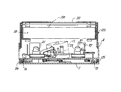
With reference to Figs. 1 to 4, 8 and 9, the
illustrated VTR comprises a main chassis 1 provided with a
head cylinder 11, and a reel chassis 2 provided with a
supply reel support 21 and a take-up reel support 22,
mounted on the main chassis 2 and slidable toward or away
from the head cylinder 11. A cassette holder 20 is
supported by a holder lift mechanism 120 on the reel chassis
2 upwardly and downwardly movably.
Figs. 1, 2 and 9 show the VTR in an e~ect mode
wherein the reel chassis 2 has been pro~ected outward from
the main chassis 1 to the greatest extent away from the head
cylinder 11, with the cassette holder 20 raised from the
reel chassis 2. In this state, a tape cassette 150 is
placed into the cassette holder 20 through a cassette inlet
10.
Fig. 3 shows the cassette holder 20 as depressed
from its position in the e~ect mode and locked to the reel
chassis 2. In this state, i.e., a standby mode, the
recorder has a depthwise length L, of 103 mm.
131~97~
Figs~ 4 and 8 show the reel chassls 2 as retracted
from its posi~ion in the standby mode toward the head
cylinder 11, with a tape loading mechanism, pinch roller
pressing mechanism, etc. brought into operation with this
movement as will be described later. The distance D the
reel chassis 2 is retracted from the standby-mode positior.
is 16 mm. With the reel chassis thus retracted, the
recorder has a minimum depthwise length L2 of 87 mm, a width
W of 109 mm and a height H of 32 mm.
Chassis Drive Mechanism 3
The main chassis 1 is rectangular as seen in Figs.
10 and 18. The reel chassis 2 is greatly cut out as
indicated at 23 at the central portion of its rear end to
avoid contact with the head cylinder 11 as seen in Figs. 16
and 19.
The main chassis 1 is provided at its opposite
sides with a pair of guide shafts l4, 15 in parallel to each
other as shown in Figs. 10 and 18. The reel chassis 2 has a
pair of slide members 24, 25 at its respective sides as
shown in Figs. 17 and 19. The guide shafts 14, 15 are
slidably fitted in the respective sllde members 24, 25 as
shown in Figs. 1 to 4, whereby the reel chassis 2 on the
main chassis 1 is guided for movement and restrained from
moving beyond a specified distance.
With reference to Figs. 12, 15 and 18, a loading
motor 31 mounted on the main chassis 1 has an output shaft
carrying a drive worm 32. A power shaft 34 extending in the
direction of movement of the reel chassis is supported at
its opposite ends by bearing members 37, 38 on the main
chassis 1 rotatably and axially movably.
Fixedly mounted on the power shaft 34 àre a
helical gear 33 meshing with the worm 32 and disposed close
to the bearing member 37 ad~acent the motor 31, and a worm
35 disposed close to the other bearing member 38. A flange
39 is secured to an intermediate portion of the power shaft
--10--
1313~79
l 34 between the hellcal gear 33 and the worm 35. A drive
piece 141 providing the holder unlocking mechanism to be
described later ls slidably fitted around the power shaft 34
on one side of the flange 39 closer to the helical gear 33.
A pair of flanges 34a, 34b arranged at a spacing are secured
to the end of the power shaft 34 close to the worm 35.
Between these flanges, the mode lever 4 to be described
later is engaged with the shaft 34.
Referring to Figs. 16 and 19, a rack 36 facing the
cutout 23 and extending along the direction of movement of
the reel chassis 2 is fixed to the reel chassis and is in
mesh with the worm 35 at all times.
Accordingly, when the helical gear 33 is driven by
the loading motor 31 to rotate the power shaft 34 in the
direction of arrow shown in Fig. 20, the worm 35 drives the
rack 36, retracting the reel chassis 2 toward the main
chassis 1, whereas if the loading motor 31 is rotated
reversely, the reel chassis 2 moves away from the main
chassis 1.
A first sensor switch 130 is mounted on the main
chassis 1 and opposed to a front end portion 2a of the reel
chassis 2 at the left side thereof. Upon the reel chassis 2
reaching its retracted limit position as seen in Fig. 21,
the front end portion 2a actuates the first sensor switch
130, whereby the completion of loading operation of the reel
chassis 2 is detected.
During the travel of the reel chassis 2, the power
shaft 34 is subfected to a thrust load, whereas 8 roller 44
provided on the mode lever 4 as will be described later
engages in a straight portion 45a of a guide channel 45 on
the reel chassis 2. This prevents the rotation of the mode
lever 4, thereby precluding the power shaft 34 from moving
axially thereof (see Fig. 21).
E~Loading Mechanism 5
With reference to Fig. 10, a cylinder unit 16
--11--
131~79
l provided on the inner central portion of the main chassis 1
comprises the head cylinder 11 having a rotary magnetic
head, a capstan 12, a capstan motor 13 for driving the
capstan, and a tape loading mechanism 5 for winding the
magnetic tape around the head cylinder 11.
The tape loading mechanism 5 comprises two ring
gears 6, 61 arranged concentrically one above the other at
two levels around a cylinder base 16a having the head
cylinder fixedly mounted thereon as seen in Fig. 11. The
ring gears 6, 61 are rotatably supported by a plurality of
support rollers 64.
Fixedly provided above the ring gears 6, 61 are
arcuate guide rails 57, 58 extending around the head
cylinder 11 and formed with guide grooves 59, 60,
respectively. A supply leader 51 and a take-up leader 54
including respective pairs of tape guides 52, 53 and 55, 56
are slidably fitted in the guide grooves 59, 60,
respectively.
The supply leader 51 and the take-up leader 54 are
connected to the upper and lower ring gears 6, 61 by
connectors 62, 63 shown in Fig. 11, respectively.
Consequently, the ring gears 6, 61, when rotating in
directions opposite to each other, move the leaders 51, 54
forward or rearward along the guide rails 57, 58.
As seen in Figs. 12 and 20, the ring gears 6, 61
are coupled to the worm 35 through a gear mechanism 7. The
gear mechanism 7 comprises first, second, third, fourth and
fifth gears 71, 74, 77, 78, 79 arranged away from the worm
35 toward the ring gears 6, 61.
Each of these gears has upper and lower two gear
portions. With the first to third gears 71, 74, 77, the
upper gear portion and the lower gear portion rotate
together, whereas in the case of the fourth gear 78 and the
fifth gear 79, the upper gear portion 78a (79a) and the
lower gear portion 78b (79b) are concentrically supported so
-12-
131~7~
1 as to rotate independently of each other and are connected
to each other by a torsion spring 78c (79c).
The lower gear portion 72 of the fist gear 71 is a
worm wheel meshing with the worm 35, and the upper gear
portion 73 thereof is in mesh with the lower gear portion 75
of the second gear 74. The upper gear portion 76 of the
second gear 74 is in mesh with the upper gear portion 77a of
the third gear 77, and the lower gear portion 77b of the
third gear 77 is in mesh with the lower gear portion 78a of
the fourth gear 78. The upper gear portion 78b of the
fourth gear 78 is in mesh with the upper gear portion 79a of
the fifth gear 79 and with the upper ring gear 6. The lower
gear portion 79b of the fifth gear 79 is in mesh with the
lower ring gear 61.
With reference to Fig. 20, the first gear upper
portion 73 and the second gear lower portion 75 meshing
therewith are each toothed locally along the outer
periphery. The upper gear portion 73 is formed with an
outwardly curved circular-arc ~ace 73a along part of the
addendum circle of the gear 73. The lower gear portion 75
is partly formed with a recessed circular-arc face 75a
having substantially the same curvature as the circular-arc
face 73a. These circular-arc faces 73a, 75a come into
engagement with each other on completion of loading of the
reel chassis 2 as seen in Fig. 21, thus providing an
intermittent rotation mechanism.
With reference to Fig. 24, the rising face of the
upper gear portion 73 extending from the bottom of the space
defining the last tooth 73c into the outwardly curved
circular-arc face 73a provides a pressing face 73b inclined
toward the face 73a beyond the usual tooth contour indicated
in a broken line, e.g. an involute. Accordingly, when the
pressing face 73b of the upper gear portion 73 pushes the
last tooth 75a of the second gear lower portion 75 to
eventually rotate the second gear 74 through a small angle
-13-
7 9
1 immediately before the completion of meshing between the
upper gear portlon 73 and the lower gear portion 75, a
common normal of the two gear faces through the point of
contact therebetween intersects a line through the centers
of rotation of the two gears at a position which is closer
to the first gear 71 than when usual two gear teeth mesh
with each other. Consequently, the angular velocity ratio
of the second gear 74 to the first gear 71 is lower than
when the usual two gear teeth mesh with each other. This
gives an increased torque to the second gear 74.
It is desired that the last tooth of the lower
gear portion 75 of the second gear 74 have a profile in
conformity with the pressing face 73b.
When the first gear 71 rotates clockwise in the
standby mode of Fig. 20, the upper ring gear 6 is rotated
clockwise through the second to third gears 74, 77, 78,
thereby moving the supply leader 51 clockwise. On the other
hand, the fifth gear 79 drives the lower ring gear 61
counterclockwise, thereby moving the take-up leader 54
counterclockwise.
As a result, the supply leader 51 and the take-up
leader 54 positioned inside the magnetic tape 151 of the
cassette 150 in the standby mode shown in Fig. 5 move along
the guide rails 57, 58, withdrawing the tape from the
cassette. While moving away from the cassette, the two
leaders are thereafter held at their limit positions shown
in Fig. 6 by coming into contact with respective stoppers
57a, 58a integral with the guide rail ends (Fig. 11),
consequently winding the magnetic tape 151 around the
periphery of the head cylinder 11 through a predetermined
angle (270 degrees), whereby the tape is completely loaded
in place.
When the two leaders 51, 54 are brought into
contact with the stoppers, the first gear 71 and the second
gear 74 meshing with each other are in the state shown in
1319~79
1 Fig. 24. The loading motor 31 further rotates from this
state, thereby bringing the pressing face 73b of the upper
gear portion 73 of the first gear 71 into pressing contact
with the lower gear portion 75 of the second gear 74 and
giving an increased torque to the second gear 74 as already
stated. The increased torque further operates the gear
mechanism 7 to thereby elastically deform the torsion
springs 78c, 79c shown in Fig. 14. The elastic force biases
the upper gear portion 78b of the fourth gear 78 and the
lower gear portion 79b of the fifth gear 79 into rotation.
whereby the supply and take-up leaders 51, 54 are pressed
against the respective stoppers 57a, 58a.
Even if the first gear 71 further rotates
clockwise from the above state, the outwardly curved
circular-arc face 73a of the first gear upper portion 73
comes into engagement with the recessed circular-arc face
75a of the second gear lower portion 75, so that the first
gear 71 idly rotates without transmitting torque to the
second gear 74 and the subsequent gears. At this time, the
reaction of the torsion spring 79c acts to rotate the second
gear 74 clockwise, but the second gear 74 will not rotate
since the circular-arc faces 73a and 75a are in engagement
with each other.
One of the important operations of the tape
loading mechanism 5 described is that the worm 35 can be
drivingly rotated by the loading motor 31 after the tape has
been completely loaded in place while the leaders 51, 54 are
being held in their limit positions on the respective guide
ralls with the circular-arc face of the first gear 71 in
engagement with the circular-arc face of the second gear 74.
This makes it possible to convert the rotation of the worm
35 to an axial movement of the power shaft 34 to effect the
operation of a pinch roller pressing mechanism 8 as will be
described below.
Pinch Roller Pressing Mechanism 8
-15-
131~79
l With reference to Figs. 16 and 25 to 27, a pinch
roller lever 82 carrying a pinch roller 81, and a drive
lever 83 are supported on the same pivot on the reel chassis
2 at the right side thereof and are rotatable independently
of each other. A spring 85 is connected between the two
levers 82, 83.
The pinch roller 81 is provided upright on a free
end of the pinch roller lever 82. The drive lever 83 has a
cam follower 84 pro~ecting downward from a free end thereof,
and an engaging pin 83a positioned close to the cam follower
84. The cam follower 84 extends through an arcuate slot 28
formed in the reel chassis 2 and engages in a cam groove 86
on the main chassis 1. The engaging pin 83a is connected to
one end of the slider 87 to be described later.
A take-up side withdrawing lever 98 is pivoted to
the reel chassis 2 a distance away from the pivot for the
pinch roller lever 82 and is connected to the lever 82 by a
link 80. Pro~ecting upward from the free end of the
withdrawing lever 98 is a pin 97 for withdrawing the
magnetic tape from the cassette in engagement therewith.
With reference to Fig. 25, the cam groove 86 on
the main chassis 1 is defined by a slanting drive face 86a
extending along the direction of retraction of the reel
chassis 2 as inclined toward the center of the main chassis
1, a parallel face 86b extending from the drive face 86a
toward the capstan 12 in parallel to the retraction
direction, and a release face 86c extending from the
parallel face 86b as inclined toward the center of the main
chassis.
Accordingly, in the course of the retraction from
the standby-mode position shown in Fig. 25 to the loading
completed position (ready mode) shown in Fig. 26, the cam
follower 84 is pushed by the slanting drive face 86a
defining the cam groove 86 to move the drive lever 83
clockwise, whereby the pinch roller lever 82 and the
-16-
131~79
1 withdrawing lever 98 are moved clockwise.
When the loading of the reel chassis 2 has been
completed, the pinch roller 81 is positioned at a small
distance from the capstan 12 as seen in Fig. 26. At this
time, the cam follower 84 is opposed to the release face 86c
defining the cam groove 86 and is freed from the restraint,
rendering the drive lever 83 free to rotate clockwise.
Referring to Figs. 16 and 25, the above-mentioned
slider 87 is supported by the rear edge of the reel chassis
2 and extends along the cutout 23 of the chassis. The
slider 87 is movable relative to the reel chassis 2
rightward and leftward over a speci~ied distance. The
slider 87 has connected to its right end the engaging pin
83a of the drive lever 83 and is provided at its left end
with a hook 88 for engagement with a slider drive pin 41 on
the mode lever 4 to be described below. Pro~ecting downward
from the midportion of the slider is a pin 89 for driving
the restraining plate 160 to be described later.
With reference Figs. 15, 22 and 23, the mode lever
4 is rotatably supported by a pivot 40 on the main chassis 1
and has one free end toward the center of the main chassis
and carrying the slider drive pin 41 and the other free end
which us bifurcated into a first pro~ection 42 and a second
pro~ection 43 for actuating second and third sensor switches
131, 132, respectively. The mode lever 4 has a driven
portion 46 in engagement with the power shaft 34 and loosely
held between the pair of flanges 34a, 34b movably axially of
the shaft 34. A roller 44 provided on the upper surface of
the mode ~ever 4 in the vicinity of the second proJection 43
is engaged in the guide channel 45 provided on the rear
surface of the reel chassis 2 as shown in Fig. 19.
The guide channel 45 has a straight portion 45a
for holding the mode lever 4 in a specified posture during
the movement of the reel chassis 2, a first slanting face
45b for permitting counterclockwise rotation of the mode
-17-
131~7~
1 lever 4 upon the retraction of the reel chassis 2 to the
loadlng completed position shown in Fi~. 22, and a second
slan~ing face 45c for permitting clockwise rotation of the
mode lever 4 when the reel chassis 2 has been brought to the
e~ect-mode position shown in Fig. 23.
When the power shaft 34 is further rotated in the
direction of arrow by the operation of the loading motor 31
with the reel chassis 2 in the loading completed position
shown in Fig. 21, the reel chassis 2 can no longer be
retracted, with the result that the worm 35 is sub~ected to
a thrust acting in the direction of e~ection of the reel
chassis (downward direction in Fig. 22) by meshing
engagement with the rack 36 in a locked state, whereby the
power shaft 34 is moved in the direction of eJection.
Consequently, the mode lever 4 is driven counterclockwise as
shown in Fig. 22.
When the drive lever 83 rotates clockwise as
already described with the retraction of the reel chassis 2
from the standby-mode position shown in ~ig. 25, the slider
87 moves leftward with this movement. On completion of
loading of the reel chassis, the hook 88 of the slider 87
engages the slider drive pin 41 on the mode lever 4 as shown
in Fig. 26.
The axial movement of the power shaft 34 rotates
the mode lever 4 from this state counterclockwise, causing
the slider drive pin 41 to slidingly move the slider 87 from
the position of Fig. 26 to the position of Fig. 27. At this
time, the roller 44 on the mode lever 4 is opposed to the
first slanting face 45b of the guide channel 45, permitting
the counterclockwise rotation of the mode lever 4 as seen in
Fig. 22.
The above movement drives the drive lever 83 and
the pinch roller lever 82 clockwise from the position of
Fig. 26. During this movement, the pinch roller 81 is
brought into contact with the capstan 12 with the magnetic
1319~79
l tape 151 interposed therebetween, and the sllder 87 further
moves slightly to thereby stretch the sprinF 85 connected
between the drive lever 83 and the pinch roller lever 82.
Under the action of the spring 85, the pinch roller 81
presses the tape 151 against the capstan 12. At this time,
the drive lever ~3 is free of restraint by the cam groove 86
and free to move clockwise.
On completion of the pinch roller pressing
operation, the first pro~ection 42 of the mode lever 4
actuates the second sensor switch 131 as shown in Fig. 22 to
deenergize the loading motor 31.
When the loading motor 31 reversely rotates with
the parts in the state shown in Fig. 22, a thrust acting on
the worm 35 upward in the drawing moves the power shaft 34
in the same direction, thereby moving the mode lever 4
lS clockwise.
At this time, the roller 44 on the mode lever 4 is
in contact with the first slanting face 45b of the guide
channel 45 on the reel chassis 2, preventing the reel
chassis 2 from moving toward the unloading direction, so
that the reel chassis 2 will not be driven by the rotation
of the worm 35.
Accordingly, the axial movement of the power shaft
34 first drives the mode lever 4 to the position of Fig. 21,
releasing the roller 44 on the mode lever 4 from the first
slanting face 45b of the guide channel 45 to allow the
movement of the reel chassis 2. The power of the worm 35 is
thereafter delivered to the rack 36, initiating the reel
chassis 2 into an unloading movement.
Back Tension Lever Mechanism 9
Fig. 16 shows a back tension lever mechanism 9
mounted on the reel chassis 2 at its left side. This
mechanism comprises a back tension lever 92 pivotally
supported on the reel chassis 2 and having a pin 91 opposed
to the supply reel support 21 for engaging the magnetic tape
--19--
1319979
l within the cassette. The lever 92 has a cam follower 93
pro~ecting downward therefrom and positioned close to the
center of rotatlon thereof. The cam follower 93 extends
through an arcuate slot 27 in the reel chassis 2 and engages
in a cam groove 95 on the main chassis 1.
A spring 99 is provided between the back tension
lever 92 and the reel chassis 2 for biasing the back tension
lever 92 in an opening direction.
The cam follower 93 has attached to its base end
one end of a brake band 94 wound around the supply reel
support 21.
With reference to Fig. 28, the cam groove 95 is
defined by a slanting guide face 95a extending progressively
away from the center of the main chassis toward the
direction of retraction of the reel chassis 2, a parallel
face 95b extending from the guide face 95a in parallel to
the direction of retraction, and a release face g5c
extending from the parallel face 95b generally at a right
angle therewith outwardly of the chassis 1.
Accordingly, with the retraction of the reel
chassis 2 in the standby mode shown in Fig. 28, the cam
follower 93 moves along the slanting guide face 95a defining
the cam groove 95, thereby rotating the back tension lever
92 toward the biasing direction of the spring 99, i.e.,
counterclockwise as shown in Fig. 30 to cause the pin 91 to
withdraw the magnetic tape 151 from the cassette.
Further with the rotation of the back tension
lever 92, the brake band 94 comes into sliding contact with
the periphery of the supply reel support 21. In this state,
the pin 91 serves as a tension sensor to ad~ust the tension
on the brake band 94, consequently lmparting suitable
tension to the magnetic tape 151. At this time, the cam
follower 93 is opposed to the release face 95c defining the
cam groove 95 as shown in Fig. 30, rendering the back
tension lever 92 free to rotate counterclockwise, i.e.,
-20-
13i9979
l tension imparting direction. In ad~usting the tension,
therefore, the cam follower 93 reciprocatingly moves between
the release face 95c and a parallel face defining the cam
groove and opposed to the release face 95c.
Reel SuPPort Drive Mechanism 100
With the present VTR, the torque of the capstan
motor 13 is transmitted to the take-up reel support 22 or
the supply reel support 21 to drive the reel support.
With reference to Figs. 10 and 18, the main
chassis 1 has mounted thereon a train of gears, lOl, i.e.,
first, second, third and fourth gears 102, 103, 104, 105
which are arranFed along the directlon of from the capstan
12 toward the front edge of the chassis 1. The first gear
102 is fixed to the output shaft of the capstan motor 13.
Further mounted on the main chassis 1 is a known
swing idler 110 at the terminal end of the gear train 101.
As shown in Fig. 13, the swing idler 110 comprises a support
arm 113 supported by the rotary shaft of the drive gear 111
always in mesh with the fourth gear 105, an idler gear 112
mounted on the free end of the support arm and meshing with
the drive gear 111 at all times, and a friction member (not
shown) provided between the drive gear 111 and the support
arm 113. The support arm 113 has a lug 114 proJecting toward
the center of the main chassis 1.
The aforementioned restraining plate 160 is
supported on the central portion of the main chassis 1 and
disposed beside the swing idler 110. The plate 160 is in the
form of an integral piece of synthetic resin and slidable
rightward or leftward over a specified distance. The
restraining plate 160 has a protrusion 161 opposed to the
lug 114 of the swing idler 110, and a cam wall 163 for the
pin 89 on the slider 87 to engage with. The cam wall 163 has
an oblique face inclined toward the swing idler 110 along
the direction of retraction of the reel chassis. The
restraining plate 160 is formed integrally with an elastic
-21-
~319~7~
1 portion 162 for biasing the plate 160 toward the idler 110.
The elastic portlon has a forward end engaged with the main
chassis 1.
With reference to Figs. 19 and 28, the reel
chassis 2 has on the rear surface of its right side a train
of gears, i.e., a fifth gear 106, sixth gear 107 and reel
drive gear 116 which are arranged along the direction of
from the chassis cutout 23 end toward the take-up reel
support 22. The reel drive gear 116 extends through the reel
chassis 2 to pro~ect above the chassis upper surface and is
in mesh with a gear portion 22a of the take-up reel support
22.
The reel chassis 2 is provided on the rear side of
its central portion with a train of gears, i.e., a first
intermediate gear 117, second intermediate gear 118 and reel
drive gear 119 which are arranged toward the direction of
from the reel drive gear 116 toward the supply reel support
21. The reel drive gear 119 extends through the reel chassis
2 to project above the chassis upper surface and is in mesh
with a gear 21a on the supply reel support 21.
When the capstan 12 rotates counterclockwise,
i.e., in the tape take-up direction, in the standby mode of
Fig. 28, the idler 110 swings counterclockwise with this
movement, bringing the idler gear 11'~ into meshing
engagement with the fifth gear 106 on the reel chassis 2.
Consequently, the rotation of the capstan motor 13
is transmitted to the take-up reel support 22 via the idler
110, fifth gear 106, sixth gear 107 and reel drive gear 116
to rotate the reel support 22 and wind up the tape.
When the reel chassis 2 is retracted from the
position of Fig. 28 toward the head cylinder 11, the idler
gear 112 on the swing idler 110 meshes with both the fifth
gear 106 and the reel drive gear 116 during the retraction
as seen in Fig. 29. Upon further retraction of the reel
chassis 2 to the loading completed position, the idler gear
-22-
1~19~7~
l 112 moves out of engagement with the fifth gear 106 and
remains in engagement with the reel drive gear 116 only as
shown in Fig. 30.
Further during the retraction of the reel chassis
2, the pin 89 on the slider 87 comes into contact with the
cam wall 163 of the restraining plate 160, slightly moving
the restraining plate 160 against the elastic portion as
shown in Fig. 25 and 26. In the state of Fig. 26, the
protrusion 161 on the restraining plate 160 has been
slightly advanced into the path of swing of the idler 110
and is in contact with the lug 144 of the idler 110, thereby
preventing the idler 110 from clockwise rotation.
Consequently, the idler gear 112 is held out of mesh with
the first intermediate gear 117.
Further in the state of Fig. 26, the capstan 12 is
in rotation clockwise, i.e., in the tape rewinding
direction, thereby exerting a clockwise swinging force on
the idler 110, so that the idler gear 112 will not mesh with
the reel drive gear 116.
Consequently, the idler gear 112 is held in a
neutral position out of meshing engagement with the first
intermediate gear 117 for the supply reel support and with
the reel drive gear 116 ad~acent the take-up reel support.
The idler gear 112 is set in the neutral position
to render the two reel supports free to rotate and permit
the magnetic tape to be paid off from the two reels during
the loading o~ the reel chassis 2. The magnetic tape is paid
off from the reels to preclude damage thereto due to the
great friction between the tape and head cylinder because
the tape is wound around the head cylinder through a large
angle.
During the subsequent retraction of the reel
chassis 2 from the position in Fig. 26 to the play-mode
position in Fig. 27, the slider 87 moves leftward, causing
the pin 89 to move the restraining plate 160 leftward by
-23-
131997~
1 pushing the cam wall 163 on the plate 160. As a result, the
protrusion 161 of the restraining plate 160 moves away from
the swing idler 110 to permit the idler 110 to swing
sidewise.
When the capstan 12 rotates counterclockwise in
the state of Fig. 30, the take-up reel support 22 is driven
clockwise to wind up the tape for usual playback or fast
forwarding.
When the capstan rotates clockwise, the swing
idler 110 swings clockwise, moving the idler gear 112 away
from the reel drive gear 116 into meshing engagement with
the first intermediate gear 117 coupled to the supply reel
support 21 as shown in Fig. 31. The clockwise rotation of
the idler gear 112 is transmitted to the gear 21a on the
supply reel support 21 via the first intermediate gear 117,
second intermediate gear 118 and reel drive ~ear 119,
whereby the supply reel support 21 is driven counter-
clockwise to take up the tape for reverse playback or
rewinding.
Holder Lift Mechanism 120
With reference to Figs. 17, and 32 to 34, the
cassette holder 20 is supported by a holder lift mechanism
120 at opposite sides of the reel chassis 2.
The holder lift mechanism 120 comprises a pair of
opposed link assemblies arranged at the respective opposite
sides of the cassette holder 20. Each link assembly
comprises a first arm 123 and a second arm 124 intersecting
each other and connected together at the intersection
rotatably relative to each other. The base end of the first
arm 123 close to the cassette inlet 10 is rotatably fitted
ln a support hole 20a formed in the side plate of the
cassette holder 20. The other end of the first arm 123 is
slidably fitted in a horizontally elongated guide slot 127
formed in the side plate of the reel chassis 2. The base end
of the second arm 124 close to the cassette inlet 10 is
-24-
1319~79
l rotatably fitted in a support hole 126 formed in the side
plate of the reel chassis 2. The other end of the second arm
124 is slidably fitted in a horizontally elongated guide
slot 20b formed in the side plate of the cassette holder 20.
5A spring 125 is connected between the first and
second arms 123 and 124.
Thus, the cassette holder 20 is liftably supported
on the reel chassis 2 and biased upward~
Holder Lock Mechanism 140
lOWith reference to Figs. 32 to 34, the left link
assembly of the holder lift mechanism 120 has coupled
thereto a holder lock mechanism 140 for locking the cassette
holder 20 in its lowered position.
To provide the holder lock mechanism 140, the
slidable end of the first arm 123 is extended toward the
main chassis, and the extremity of the extension has a lock
pin 128 pro~ecting inwardly o~ the holder.
On the other hand, a lock arm 146 is pivoted to
the left side plate of the cassette holder 20 at one end
thereof opposite to the cassette inlet 10 and is biased
20counterclockwise in Fig. 34 by a spring 170 connected
between the arm 146 and the reel chassis 2. The lock arm 146
is provided at its free end with a hook 147 engageable with
the lock pin 128 and an outwardly pro~ecting pressing pin
148 in the vicinity of the hook 147. The lock arm 146 is
prevented from moving counterclockwise beyond a limit
position by a stopper 129 provided on the cassette holder
20.
The rear end of the reel chassis side plate is
formed with a cam portion 29 slanting rearwardly downward
and opposed to the pressing pin 14B on the lock arm 146.
Accordingly, when the cassette holder 20 is
depressed in the eJect mode of Fig. 34, the pressing pin 148
comes into contact with the cam portion 29, which in turn
slightly rotates the lock arm 146 clockwise. At the same
-25-
1~9379
1 time, the first arm 123 rotates toward a horizontal
position. When the cassette holder 20 is further depressed
to its lowered limit position, the pressing pin 148 is
released from the cam portion 29, whereupon the lock arm 146
is rotated counterclockwise by the action of the spring 170
as shown in Fig. 32. Consequently, the hook 147 of the lock
arm 146 engages with the lock pin 128 on the first arm 123
to lock the holder 20 in its lowered limit position.
The cam portion 29 is provided on its inner
surface with a fourth sensor switch 133 as positioned below
the pressing pin 148. With the cassette holder 20 in its
locked position, the switch is closed by the pressing pin
148 as seen in Flg. 32 to detect the locked state of the
holder, whereupon the reel chassis is initiated into loading
movement.
Holder Unlocking Mechanism
The holder lock mechanism 140 is unfastened by
moving a slide plate 144 on the main chassis 1 to thereby
move the lock arm 146 counterclockwise and disengage the
hook 147 from the lock pin 128.
With reference to Figs. 21 and 23, the slide plate
144 is disposed at one side of the power shaft 34 and is
slidable over a specified distance along the direction of
movement of the reel chassis 2. The plate 144 is biased
toward the reel chassis 2 by a torsion spring 145 on the
main chassis 1. The slide plate 144 has, at one end thereof
ad~acent to the reel chassis 2, a first lug 171 engageable
with the lock arm 146 and, at the other end, a second lug
172 engageable with one of two free ends of a driven lever
143.
The driven lever 143 and a drive lever 142 are
pivotally supported on the main chassis 1. The slide plate
144 is operatively connected to the aforementioned drive
piece 141 fitted around the power shaft 34, through these
levers 143, 142. The drive lever 142 is formed at its free
-26-
7~
l end with a pair of engaging portions which are in a
back-to-back arrangement. One of these engaging portions is
in contact wlth the drive piece 141, and the other engaging
portion with the other free end of the drive lever 143. The
first-mentioned free end of the drive lever 143 extends over
the slide plate 144 and bears against the second lug 172 of
the slide plate 144.
When the power shaft 34 is rotated in the
direction of arrow shown by the operation of the loading
motor 31 after the reel chassis 2 has been completely
unloaded as seen in Fig. 20, the reel chassis 2 no longer
advances, with the result that the worm 35 is sub~ected to a
thrust acting in the direction of retraction of the reel
chassis (upward in Fig. 20) by the rack 36 in a locked state
and meshing with the worm 35, whereby the power shaft 34 is
moved in the direction of retraction. Consequently, the mode
lever 4 is driven clockwise as shown in Fig. 23. At this
time, the roller 44 on the mode lever 4 is opposed to the
second slanting face 45c of the guide channel 45 to permit
the clockwise rotation of the mode lever 4.
With the above axial movement of the power shaft
34, ~he drive piece 141 drives the drive lever 142
counterclockwise as shown in Fig. 23, and the drive lever
142 in turn drives the driven lever 143 clockwise, causing
the driven lever 143 to move the slide plate 144 toward the
direction of reel chassis against the spring 145.
With this movement, the first lug 171 pushes the
free end 149 of the lock arm 146 to move the arm 146
clockwise as seen in Fig. 33, thereby disengaging the hook
147 from the lock pin 128 and unlocking the cassette holder
20. Consequently, the cassette holder 20 is raised by the
action of each spring 125 as seen in Fig. 34. At the same
time, the lock arm 146 is returned counterclockwise to its
limit position.
The slide plate 144 is thereafter returned toward
-27-
13~79
l the reel chassis 2 to the broken-line position shown in Fig.
34 as will be described below, whereby the lock mechanism is
made ready for the subsequent operation.
When the power shaft 34 in the state of Fig. 2~ is
rotated in a direction opposite to the dlrection of arrow by
the operation of the loading motor 31, a thrust acting on
the worm 35 downward in the drawing moves the power shaft 34
in the same direction. This movement returns the mode lever
4 to the position of Fig. 20 and the slide plate 144 to the
position shown in Fig. 32.
In the state of Fig. 23, the roller 44 on the mode
lever 4 is in contact with the second slanting face 45c of
the guide channel 45 on the reel chassis, preventing the
reel chassis from retraction, so that the rotation of the
worm 35 will not move the reel chassis.
Consequently, the power shaft 34 first moves
axially thereof to drive the mode lever 4 to the position
shown in Fig. 20. The roller 44 on the mode lever 4 moves
away from the second slanting face 45c of the guide channel
45, permitting the movement of the reel chassis 2. The
torque of the worm 35 is then delivered to the rack 36,
initiating the reel chassis 2 into loading movement.
Holder Positioning Mechanism
The holder positioning mechanism to be described
below is used for holding the cassette holder 20 at a
specified level above the main chassis 1 in the state shown
in Fig. 32.
With reference to Figs. 9, 10 and 17, the right
side plate o~ the cassette holder 20 has an engaging pin 121
pro~ecting outward from its rear end.
On the other hand, the main chassis 1 has at the
rear end of its right side portion a U-shaped hooked piece
122 which is opened toward the front. The hooked piece 122
ls so positioned that the engaging pin 121 snugly fits
therein when the reel chassis 2 has been completely loaded
-28-
131~37g
1 as shown in Fig~ 4.
Thus, the left side plate of the cassette holder
20 is held at ~he specified level above the main chassis 1
by the engagement of the lock arm 146 with the lock pin 128
in the state of Fig. 28 and remains so held also on
completion of loading and in the play mode shown in Fig. 4.
The right side plate of the cassette holder 20 is also held
at the specified level by the engagement of the engaging pin
121 with the hooked piece 122 as seen in Fig. 4.
Consequently, the tape cassette within the
cassette holder 20 is maintained horizontally at the
specified level above the main chassis 1 in the play mode.
The engaging pin 121 is electrically connected to
the cassette holder 20, and the hooked piece 122 is
electrically connected to the main chassis 1, whereby the
cassette holder 20 is grounded to the main chassis 1 to
magnetically shield the interior of the cassette holder 20.
Consequently, the magnetic head and rotary transformer of
the head cylinder 11 to be surrounded by the holder 20 in
the play mode are protected from external magnetic noises.
Other ComDonents
With reference to Fig. 8, the reel chassis 2 is
provided at the front edge of its midportion with a reel
unlocking piece 26 for unfastening a reel lock mechanism
(not shown) provided inside the cassette.
The reel chassis 2 is further provided with a
light-emitting member 134 at the rear edge of its midportion
and with a tape end sensor 136 and a tape top sensor 137 on
its respective side plate for receiving light from the
member 134 to thereby detect whether the magnetic tape in
the cassette inside the holder 20 in the play mode has been
wound up on the take-up reel completely (tape end state) or
rewound on the supply reel completely (tape top state).
With reference to Fig. 9, the second arm 124 on
the right side constituting the holder lift mechanism 120
-29-
1319~79
l has a circular-arc gear piece 173 pro~ecting therefrom. The
reel chassis 2 is provided with a damper 174 meshing with
the gear piece 173 for offerin~ suitable resistance to the
rise of the cassette holder 20.
S As seen in Fig. 19, the reel chassis 2 has a
supply reel rotation sensor 138 and a take-up reel rotation
sensor 139 disposed on the rear side of and opposed to the
supply reel support 21 and the take-up reel support 22,
respectively, for detec~ing the rotation of the respective
reels. The rotation sensor 138, 139 each comprises, for
example, a photoreflector.
Circuit Construction
Fig. 35 shows the construction of a control
circuit for controlling the operation of the capstan motor
13 and the loading motor 31.
A system controller 180 for controlling the
operation of the VTR in various modes comprises a
microcomputer and has connected to its input ports the
foregoing first to fourth sensor switches 130, 131, 132,
133, 134, a cassette detection switch 135, the tape end
sensor 136, the tape top sensor 137, the supply reel
rotation sensor and the take-up reel rotation sensor 139.
Drivers 13a, 31a are connected to the output ports of the
controller 180 for producing drive voltage for the capstan
motor 13 and the loading motor 31, respectively.
The system controller 180 has stored therein a
computer program for effecting the mode changes to be
described below in response to command signals from
manipulation keys (not shown) on the operation panel of the
VTR, and also a computer program for performing the
operations unique to the VTR of the inventlon and to be
described below with reference to Figs. 36 to 40.
Main Mode Changes
The present VTR is settable in five modes. These
modes include eJect mode wherein the cassette holder is
-30-
1319379
l raised for the tape cassette to be plsced therein, standby
mode wherein t~e reel chassis depressed in the eject mode is
locked to the reel chassis, play mode wherein signals can be
recorded or reproduced after the reel chassis has been
loaded in place from the standby-mode position, followed by
tape loading, pressing of the pinch roller against the
capstan, etc., stop mode wherein the head cylinder and the
capstan rotating in the play mode are stopped, and ready
mode wherein the pinch roller pressed against the capstan in
the play mode or stop mode is released from the capstan.
(1) Change from Standby Mode to Ready Mode (Loading
Completed State)
In the standby mode wherein the cassette holder 20
is locked to the reel chassis 2 as shown in Fig. 3, a
loading command is given by the operation panel, whereupon
the loading motor 31 is initiated into rotation, retracting
the reel chassis 2 from the standby-mode position of Fig. 5
to the loading completed position of Fig. 5, whereby the
first sensor switch 130 is actuated as seen in Fig. 21.
In this step, the back tension lever 92, the
take-up side withdrawing lever 98 and the pinch roller lever
82 are moved toward the tape withdrawing direction, and the
supply and take-up leaders 51, 54 are moved, whereby the
magnetic tape 151 is positive along the specified path as
shown in Fig. 6. Further the mode lever 4 and the slider 87
engage with each other.
(2) Change from Ready Mode to Play Mode
Further continued rotation of the loading motor 31
in the ready mode of Fig. 6 moves the power shaft 34 axially
thereof from the position of Fig. 21 to the position of Fig.
22, causing the mode lever 4 to pull the slider 87 to
thereby bring the pinch roller 81 into pressing contact with
the capstan 12 with the tape 151 positioned therebetween as
seen in Fig. 7.
Consequently, the second sensor switch 131 is
-31-
1319979
1 turned on as shown in Fig. 22, and the ON signal is sent to
the system contrGller to stop the loading motor 31.
The head cylinder 11 and the capstan motor 13
rotate in the play mode of Fig. 7 to record or reproduce
signals.
Further in the play mode, the capstan 12 is
rotated at an increased speed to forward the tape fast or
rewind the tape.
(3) Change from Play Mode to Stop Mode
In response to a command given by the operation
panel for a change to the stop mode, the head cylinder 11
and the capstan 12 stop from rotating. The reel chassis 2
remains in the position of Fig. 7.
(4) Change from Play Mode or Stop Mode to Ready Mode
For example when a slack occurred in the tape
between the capstan and the head cylinder during tape
rewinding as will be described later, the VTR is set in the
ready mode in which the pinch roller is released from
pressing contract with the capstan as shown in Fig. 6.
In this case, the operation of the loading motor
31 drives the power shaft 34 axially thereof from the
position in Fig. 22 to the position in Fig. 21. This
movement moves the slider rightward from the position of
Fig. 27 to the position of Fig. 26, freeing the pinch roller
81 from pressing contact with the capstan 12. This is
detected by the opening of the first sensor switch 130 in
Fig. 21, and the loading motor 31 is stopped by the
resulting detection signal.
(5) Change from Ready Mode to Standby Mode
The rotation of the power shaft 34 in a direction
opposite to the arrow in the state of Fig. 21 drives the
reel chassis 2 to the standby-mode position of Fig. 20.
Further the first gear 71, when rotated
counterclockwise by the rotation of the worm 35 in the state
of Fig. 21, moves the outwardly curved circular-arc face 73a
131~;~79
1 of the upper gear portion 73 of the gear 71 out of contact
with the recessed clrcular-arc face 75a of the lower gear
portion of the second gear 74, permitting the upper and
lower gear portions 73, 75 to come into meshing engagement
with each other. As a result the rotation of the worm 35 is
transmitted to the two ring gears 6, 61 via the gear
mechanism 7, returning the supply and take-up leaders 51, 54
from the position in Fig. 6 to the tape loading start
position within the cassette 150 as shown in Fig. 5.
Simultaneously with this, the supply side and
take-up side withdrawing levers 92, 98 and the pinch roller
lever 82 are also returned to the tape loading start
position inside the cassette.
Concurrently with the return of the leaders 51,
54, the take-up reel support 22 is driven in the tape
winding direction as will be described later, whereby the
magnetic tape 151 drawn out toward the head cylinder 11 is
rewound into the cassette.
The reel chassis 2 moves form the standby-mo~e
position to the subsequent e~ect-mode position without
stopping in the former mode.
(6) Change from Standby Mode to E~ect Mode
The power shaft 34, when rotated in a direction
opposite to the arrow in the standby mode shown in Fig. 20,
moves axially thereof as shown in Fig. 23, thereby moving
the slide plate 144 against the torsion spring 145, with the
result that the cassette holder 20 is unlocked and rises as
seen in F~gs. 32 to 34.
The e~ect mode shown in Fig. 23 is detected 100
msec after the third sensor switch 132 is closed. The
loading motor 31 is stopped in response to the resulting
detection signal.
Unique OPerations
(1) Tape Slack Treating Process
If the magnetic tape stops in contact with the
-33-
1319`37~
l periphery of the head cylinder owlng to the friction
therebetween during tape rewinding, the tape slackens
between the cylinder and the capstan. To remedy the slack.
the operation illustrated in Fig. 38 is conducted according
to a program.
The tape slack treating process will be descried
with reference to Fig. 38.
If the tape slackens between the head cylinder 11
and the capstan while it is being rewound, the supply reel
support 21 only stops rotating. This is detected by the
supply reel rotation sensor 138 (Fig. 38, 181). In response
to the resulting detection signal, the rotation of the
capstan 12 is interrupted temporarily (Fig. 38, 182). Next,
the loading motor 31 is brought into rotation in the
unloading direction to release the pinch roller 81 from the
capstan 12, and the capstan 12 is rotated at 7 times the
usual speed for playback in FWD direction (direction in
which the magnetic tape is forwarded toward the take-up
reel, Fig. 38, 183), whereby the take-up reel support 22 is
rotated toward the tape winding direction. Subsequently,
upon the start o~ rotation of the supply reel support 21 or
5 seconds thereafter, the capstan 12 and the head cylinder
11 are stopped (Fig. 38, 184).
Thus, the slack is removed by winding the tape on
the take-up reel.
The control system thereafter accepts only an
instruction for e~ection or to turn off the power supply.
The above 5-second time interval is provided by a
timer in order to protect the tape in the case where the
supply reel support 21 fails to rotate for one cause or
another.
(2) Tape Unloading Process
If there is some obstacle hampering the movement
of the reel chassis 2 ahead of the chassis 2 or the cassette
holder 20 during the unloading operation of the reel chassis
-34-
131~79
l 2, the torque produced by the loading motor 31 wlll act as a
load on the Mechanism from the motor 31 through the reel
chassis 2, possibly causing damage to thls mechanism.
With the present VTR, the voltage for driving the
loading motor 31 for unloading the reel chassis 2 is set to
a lower level than that for the loading operation to
minimize the possible damage (Fig. 36, periods T~, T9, T4).
The drive voltage for unloading can be made lower
than for loading because the mechanism can be free of the
load for withdrawing the tape during unloading and therefore
requires a smaller drive force for unloading than for
loading.
Figs. 36A (a) and (b) show the drive voltsges to
be applied to the loading motor 31 for loading and
unloading, respectively.
For loading, 5-volt d.c. voltage is applied to the
loading motor 31 as shown in Fig. 36A (a), whereas for
loading, pulse width modulated drive pulses, 20 msec in
period and 40% in duty, are applied to the loading motor 31
so that the loading motor 31 is driven with a voltage
levelled to about 2 V as shown in Fig. 36A (b).
~3) Tape Winding Process for Unloading
When the loading motor 31 is started toward the
unloading direction in the ready mode of Fig. 21, the
rotation of the worm 35 is transmitted to the rack 36 to
start driving the reel chassis 2. However, the rotation of
the first gear 71 of the gear mechanism 7 is not transmitted
to the ring gears 6, 61 immediately owing to the
intermittent rotation mechanism afforded by the circular-arc
face 73a and the circular-arc face 75a, but is transmitted a
predetermined period of time after the start of movement of
the reel chassis 2. More specifically, the supply and
take-up leaders 51, 54 start an unloading movement when the
upper gear portion 73 of the first gear 71 comes into
meshing with engagement with the lower gear portion 75 of
-35-
i3193~9
l the second gear 74.
Accordlngly, during the process in which the reel
chassis 2 only moves along, the movement of the cassette on
the chassis 2 withdraws the magnetic tape from the cassette,
and the subsequent movement of the leaders 51, 54 in the
unloading direction slackens the tape.
The slack in the tape is removed by the winding
process described below.
Figs. 36 (a) to (e) show the timing of various
control signals produced during unloading. Fig. 36 (a) shows
LOAD END signal which changes to "H" upon opening of the
first sensor switch 130. Fig. 36 (b) shows L~AD TOP signal
which is changed to "H" by the opening of the second sensor
switch 131 and to "L" by the closing of the third sensor
switch 132. Fig. 36 (c) shows a cylinder ON signal for
starting the head cylinder 11. Fig. 36 (d) shows a capstan
ON signal for rotating the capstan 12 ln FED direction. Fig.
36 (e) shows an unload ON signal for initiating the
unloading motor 31 into rotation in the unloading direction.
Fig. 39 shows a program stored in the system
controller.
The tape winding process for unloading will be
described with reference to Figs. 36 and 39.
When the reel chassis is to be unloaded in the
stop mode, the head cylinder 11 is initiated into rotation
first, and the pinch roller 81 is released from the capstan
(Fig. 36, period T " Fig. 39, 185-186) for a change to the
ready mode. Su~sequently, upon lapse of 100 msec as shown in
Fig. 36 (d), the capstan 12 is rotated at Xl (usual speed)
for 30 msec in RVS direction (direction in which the tape is
rewound on the supply reel)(Fig. 39, 187), whereby the idler
gear 112 is set in the neutral position as seen in Fig. 26.
When the reel chassis is to be unloaded in the ready mode,
the sta,t of rotation of the head cylinder 11 is immediately
followed by the rotation of the capstan 12 (Fig. 39, 187).
131~79
1 The idler gear 112 is thus set in the neutral position to
permit the tape to be paid off from the two reels when the
reel chassis 2 moves with the leaders 51, 54 held at a stop
as stated above.
Next, the loading motor 31 is started in the
unloading direction to move the reel chassis 2 toward the
standby-mode position. The LOAD END signal thereafter
changes to "H" as shown in Fig. 36 (a), whereupon the
capstan 12 is rotated in FWD direction. In this way, the
capstan 12 is held stopped while the reel chassis 2 only is
moving (Fig. 36, period T2) to prevent the tape from being
displaced by being wound on the take-up reel.
For 30 msec (Fig. 36, period T3) following the
change of the LOAD END signal to "H", the capstan 12 is
rotated at 5 times the usual speed (Fig. 39, 188). For the
subsequent period until the e~ect mode is set up (Fig. 36,
periods T4 and T~), the capstan 12 is driven at 9 times the
usual speed (Fig. 39, 189) to wind up the tape paid off from
the cassette on the take-up reel. In this way, the capstan
12 is rotated at a low speed during a short period of time
following the start of movement of the supply and take-up
leaders 51, 54 for the following two reasons. Owing to the
engagement of the pressing face 73b of the first gear 71
with the second gear 74, the speed of the leaders
immediately after the start of their movement is lower than
when usual teeth of the two gears 71, 74 are in mesh (see
Fig. 24), so that the amount of slack of the tape due to the
movement of the leaders is initially small and thereafter
increases. Accordingly, the tape winding speed is made lower
for a short period of time immediately after the start of
movement of the leaders to thereby prevent displacement of
the tape due to unloading. Further the time when the LOAD
END signal changes to "H" as shown in Fig. 36 (a) inevitably
slightly differs from the time when the leaders actually
start moving, so that the tape becomes displaced if wound up
7 ~
l at a high speed from the beginning despite the delay of the
start of movement of the leaders.
When the reel chassis 2 has been completely
unloaded upon the lapse of the period T4 shown in Fig. 36,
5 the LOAD TOP signal changes to "L" as seen in Fig. 36 (b).
After the LOAD TOP signal has changed to "L", the
loading motor 31 is further rotated in the unloading
direction with the usual drive voltage (5 Y) only for 100
msec (Fig. 39, 190) to thereby unlock the cassette holder
20.
Finally, the loading motor 31, the capstan 12 and
the head cylinder 11 are stopped (Fig. 39, 191) to complete
the process.
Consequently, the tape can be withdrawn smoothly
at the start of unloading, and the reel cassette can be
unloaded without greatly displacing the tape and free of
slackening.
(4) Tape Handling Process to be Practiced When Cylinder is
to be Stopped
For the change to the stop mode, the capstan 12
and the head cylinder 11 are stopped without releasing the
pinch roller 81 from the capstan 12 as already stated so as
to effect a rapid change from the stop mode to the play
mode.
However, to smoothly bring the head cylinder 11
into operation from the stop mode, there is a need to give
some slack to the magnetic tape between the head cylinder 11
and the capstan 12.
For a change to the stop mode, therefore, the
capst.an is rotated in the RVS direction for a specified
period of time to intentionally slacken ` the tape.
Nevertheless, the capstan 12, if merely driven in the RVS
direction, gives rise to the ob~ection that the rotation of
the idler gear 112 rotates the supply reel support 21 as
shown in Fig. 21 to rewind the tape. This is avoided by the
131997~
1 following procedure.
When the stop mode is to be set up, the capstan
motor 13 ls lnitiated into rotation in the R~S direction
wlth the swing idler 110 coupled to the take-up reel support
2~ as seen in Fig. 30, whereby the tape is paid off toward
the head cylinder 11 by the capstan 12 and thereby slackened
during the swing of the idler 110 toward the supply reel
support 21.
More specifically, this process is executed in the
following manner.
Figs. 37 (a), tb) and (c) are timing charts
showing the capstan ON signal to be sent from the system
controller 180 to the driver 13a for the capstan motor 13,
and the capstan RVS signal for rotating the capstan motor in
the RVS direction.
When the play mode is to be changed to the stop
mode, the swing idler 110 is already coupled to the take-up
reel support 22 in the play mode, so that the capstan is
rotated at Xl, i.e. at the usual speed, in the RVS direction
for 50 msec as seen in Fig. 37 (a) to slacken the tape.
When CUE (fast forward playback) mode or FF (fast
forward) mode is to be changed to the stop mode, the capstan
is temporarily stopped and then rotated at the usual speed
in the FWD direction for about 1 sec as shown in Fig. 37 (b)
to bring about the same state as shown in Fig. 37 (a),
followed by the same operation as in Fig. 37 (a) to give the
tape the same amount of slack as for the change from the
play mode to the stop mode.
Further when REV (reverse playback) mode or REW
(tape rewindlng) mode is to be changed to the stop mode, the
swing idler is coupled to the supply reel support, so that
the capstan is first stopped and then rotated at the usual
speed in the FWD direction for about 1 second to couple the
idler to the take-up reel support, followed by the same
operatJon as in Fig. 37 (a) to slacken the tape.
-39-
131~79
Consequently, the head cylinder can be smoothly
initiated into rotation from the stop-mode state with the
pinch roller held in pressing contact with the capstan.
(5) Tape End Handling Process
As already described, the tape to be loaded in
paid off from both the supply reel and the take-up reel and
thereby protected to the greatest possible extent from the
damage due to the friction between the head cylinder and the
tape.
However, if the cassette in the holder is in the
tape end state when the tape is to be loaded, the tape is
paid off from the take-up reel only and is therefore likely
to be damaged.
Accordingly, if the cassette is in the tape end
state when the tape is to be unloaded, the tape is rewound
by an amount corresponding to the amount of tape to be paid
off from the supply reel for tape loading, and the tape is
then unloaded. Consequently, when the cassette is removed
from the VTR and thereafter loaded into the VTR again, the
tape can be loaded by being paid off from both the reels.
This process is executed according to the program
shown in Fig. 40.
When an e~ect command is given by the operation
panel, the tape top sensor 137 and the tape end sensor 136
indicate whether the cassette is in the tape top state and
whether it is in the tape end state (Fig. 40, 192, 193,
194).
If the tape top sensor is on and the tape end
sensor is off, or if both the sensors are off, the head
cylinder 11 is initiated into operation, followed by
e~ection as indicated at 195.
If the tape sensor is off with the tape end sensor
on, this indicates that the cassette is in the tape end
state, so that the head cylinder 11 is started, and the
pinch roller 81 is thereafter pressed against the capstan 12
-40-
131~73
1 (Fig. 40~ 196)~
The capstan 12 is then rotated at 7 times the
usual speed in the RVS direction for 1 second to rewind the
tape as already stated.
The capstan 12 is subsequently stopped, followed
by e~ection (195)~
Consequently, when the cassette in the tape end
state after signal recording or reproduction is loaded into
the VTR again, the tape can be loaded in place by being paid
off from both the cassette reels, whereby the tape can be
protected from damage.
The drawings and embodiment are given for the
illustration of the present invention and are not to be
interpreted as limlting or reducing the scope of the
invention as defined in the appended claims.
The construction of the apparatus of the invention
is not limited to the foregoing embodiment but can be
modified variously by one skilled in the art without
departing from the spirit of the invention disclosed in the
claims.