Note: Descriptions are shown in the official language in which they were submitted.
132~
REMOVA~LE SYRUP PA~KAGE
Backqro~n~ o~ th~-lnven~iQa
.This ~invention relates generally to contai~ers
: for dispensing liquids and more particularly to a
removable and disposable package and an actuated closure
cap assembly therefor for use in a post-mis soft drink
type beverage dispensing system.
Post-mi~ beverage dispensing apparatus is
generally known, with the more common form of such
apparatus being the commercially available post-mi~
b~verage dispenser units which have been designed for
large volume commercial uses such as used in fast food
restau~nts. More recentl~, how~ver, attempts have been
made in the industr~ to reduce the cost~ size and weight
of such b~verage dispe~sing units to make them available
to the geDeral public for private use.
& ch apparatus, moreover, typically include a
removably disposable package for dispensing liquids such
: as~ a~syTup mi~ture whi-c~ is then m~ed with carbonated
, ~ :
.
-
132~80
water at a mixing head located adjacent the dispensing
outlet. For such systems to be acceptable to the
consuming public, supplies of these ingredients must be
capable of being quickly and easily replenished by a user
who may be relatively unskilled. In addition, the syrup
component must be made available, for example at
supermarkets in the form of a quickly and easily
replaceable disposable package. An example of a
disposable syrup package which may be used in a small
post-mix beverage dispensing system is disclosed in U.S.
Patent No. 4,216,885 which issued to J.K. Sedam, on
August 12, 1980. This patent is assigned to the assignee
of the present invention.
Summary_~f the Invention
Accordingly, it is an object of an aspect of
the present invention to provide an improvement in post-
mix beverage dispensing systems.
It is an object of an aspect of the invention
to provide an improvement in a removable container for
dispensing a liquid in a post-mix beverage dispensing
system.
It is an object of an aspect of the invention
to provide an improvement in closure means utilized in
connection with a removable package utilized in
connection with a post-mix beverage dispensing system.
It is an object of an aspect of the invention
to provide a removable and disposable package and closure
therefor that is simple in construction, economical to
produce and reliable in operation so that it can be
incorporated in a relatively maintenance free beverage
dispensing system.
An aspect of this invention is as follows:
Apparatus for a beverage dispensing system
comprising:
a removable package containing liquid to be
dispensed and including a body portion and a liquid
~.
~ ~3201~0
2a
discharge portion having a discharge port therein from
which said liquid may be dispensed;
an actuated closure assembly including a
stationary facing member disposed over said discharge
port and having an air inlet opening and a liquid outlet
opening therein, and a cap member pivotally attached to
said facing member and having means for closing off said
air inlet opening and said liquid outlet opening when in
contact therewith during a closed operating state and
exposing said openings when said cap member is pivoted
away from said facing member during an open operating
state; and
actuator means for pivoting said cap member
between said closed and op~n operating state, said
actuator means comprising a movably driven member in
contact with said cap member and being movable between a
first and a second position to effect said closed and
open operating stateO
By way of added explanation, the foregoing and
other cbjects are accomplished in one embodiment of the
invention by a removable and disposable package type of
' ~ :
,,,,.,,,,,.,,
3~32~180
container ~or dispensing a liquid, such as syrup, and an
a~tuated closure mechanism therefor, which in its brsadest
aspect, comprises an upper b4dy portion from which a lower
discharge portion e~tends outwardly therefrom and which
S include5 a generally horizontal discharge op~ning or port
projectin~ therefrom. The closure assembly is comprised
of a movable outer cap member pivotally attached to a
facing member. The facing member fits over the discharge
port and includes a syrup outlet opening and an air inlet
openin~ therein. The cap member includes means for
closing off both openings when in contact with the facing
member. An actuator contacts the cap member such that
when a dispensing operation is reguired, the cap memb~r is
swung outwardly away from the facing member, e~posing the
1~ syrup outlet and air inlet openings. When the dispensing
operation is completed, the actuator urges the cap member
back into contact with the facing member to reseal the
openings.
Des~riPtion of the Drawina~
Further objects and advantages and f atures of
this invention will become apparent when th~ following
specification is co~sidered with the accompanying drawings
wherein:
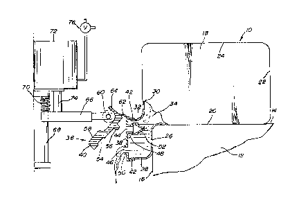
Figure 1 is a mec~anical schematic diagram,
partially in section, of the preferred embodiment of the
subject invention in a first or closed operating state; and
Figure 2 is a schema~ic mechanical diagram of the
apparatus shown in Figure 1 in a second or open operating
state.
Des~riPtion of ~he Preferr~d Embodimen~
Referring now o the drawings ~herein li~e
refere~ce numerals refer to identical parts throughout,
reference numeral 10, for e~ample~ denotes a removable
syrup container i~ th~ form of a fle~ible package for use
~ . ............................ .
4 l32~180
in a carbonat~d post-mis beverage dispenser. The
dispenser, per se, is not shown e~cept for a support
member 12 shown having a generally horizontal support
surface 14 and a generally vertical side surface 16.
As shown in both Figures 1 and 2, the package 10
includes a generally rectangularly shaped upper body
portion 18 which functions as a liquid reservoir for syrup
or the like and includes an elongated bottom wall 20,
When the package is installed in a dispenser, the bottom
wall 20 rests on the surface 14 of the dispenser member
12. The bottom wall 20 terminates in a rear wall 22 which
e~tends upwardly to a top wall 24. Th~ forward portion of
the bottom wall 20 terminates in a discharge portion which
includès a downwardly e~tending front wall portion 26
having a generally horizontal end section 28. The body
portion 18 additionally includes a front ~all 30 which
e:~tends downwardly f rom the top wall 2~ where it
terminates in a generally horizontal end section 32 which
is separated from the wall section 28 and form the tsp
part of34the discharge portion. A relatively small channel
region/ is provided between the bottom and front walls 20
and 30 ~or passage of liquid downwardly therethrough.
A mechanically actuated closure assembly 36 is
fitted over the lower outlet portion of ~he housing 18 as
25 defined by the wall portions 2~ and 3-2 as well as a pair
of opp~sing corresponding side wall portions, ~ot shown,
so as to form a four sided aischarge port. The closure
assembly 36 is comprised of a stationary ~a~ing member 38
and a moYable cap member 40 which is hingedly attached at
30 its u~per e:~tremity thereto. The faci~g F~ember 38
includ~s flange ~ectio~s 42 which when fitted to the body
:~ portions 18, engag~ th~ wall sectio~s 28 and 32 as shown
and ~he corresponding sid wall sections, not shown~ The
. 5 l 3201~
facing member additionally includ~s an upper air inlet
opening 44 and a lower li~uid outlet opening 46. ~he air
inlet openiny 44 is formed by inwardly projecting wall
members 4~ while the liquid outlet opening 46 is formed by
outwardly projecting wall member 50. The spenings 44 and
46 are configured as generally circular openings; however,
it should be noted that when desirable rectangular
openings could just as easily be formed.
Additionally, an air check valve device 52 is
attached to the inwardly projecting wall portions 48 of
the air inlet 44 to permit continuous liquid flow from the
outlet 46 when the cap member 40 is opened. ~he check
valve device 52 can be of a "duck bill~ type valve and
functions to prevent any liquid from flowing out of the
air inlet 44 at the ~ery be~inning of a liquid dispensing
operation from the package lO. However, any suitable type
of check valve can be used. When desirable, however, this
device can be eliminated in certain circumstances where a
small amount o outflow from the air inlet 44 might be
tolerated.
The construction of the cap member 40 includes an
inner recess 54 for fitting over the outwardly projecting
wall port;ons 50 of the li~uid outlet 46 and an outwardly
projecting tip 56 which fits into the air inlet 44 in the
2~ closed position. The outer surface 58 of the cap member
40 comprise5 a cam type surface which engages a spring
biased xolles 60 of an actuating mechanism for opening and
closing the cap member over.the facing member 38. A
resilient hinge member 62 spans the upper flange 42 of the
facing member 3~ and an upper shoulder portion 64 of the
cap member 40; however, any type of pivot element can be
utilized.
~ he roller 60 is further shown in Figures 1 and 2
connected to an arm 66 which includes a roller bias spring
- - ~ 132~8~
67 and which slides vertically on ~ guide rod 68 whicn
includes a compression spring 70 located thereon. The
compression sprin5 70 biases the roller downwardly against
the raised portion of the outer cap sur~ace 58 which
S causes the cap member 40 to close against the facing
member 3B and thus obstruct both the liguid outlet opening
46 and the air inlet opening 44. This consti~utes the
closed operating state of the apparatus.
An open operating state is effected when a
liquid, e~g. syru~ dispensing operation is required. At
such time, the roller 60 is urged upwardly i~to the
depressed portion of cam surface 58 of the cap surface 40
where it abuts th~ shoulder portion 64 thereof. This
causes the cap member 40 to pivot and swing outwardly and
thus e~pose the air inlet o~ening 42 and the liquid outlet
opening 46. This operation is provided in the embodiment
shown by a pneumatic cylinder 72 coupled to the arm 66 by
means of a piston rod 74 which retr~cts when air pressure
is fed into the lower part of the pneumatic cylinder 72 by
means of a hree way valve 76 which in one position feeds
air pressure from a source, not shown, to the pneumatic
cylinder, while in its other poeition against the air
pressure within the c~linder to the outside atmosphere~
whereupon the spring 70 urges the roller 60 back into the
2~ closed position of the apparatus as shown in Figure 1.
Thus what has been shown and described is a
Temovable liquid package for acting as a syrup reservoir
for a post-mi~ beverage dispensing system and which
additionally includes a relatiYely simple yet effective
hinged closurQ cap assembly. ~he assembly is actuated by
a spring loaded ~oller member which operatee t~ pivotally
open and close the cap me~ber against a stationary facing
which includes an air inlet opening and a fluid outlet
opening.
1~2~180
. - ~ 7
Having thus shown and described what is at
present considered to be the preferred embodiment of the
invention, it should be noted that the same has heen made
by way of illustration and not limitation. Accordingly,
all modificationS, alterations and changes coming within
the spirit and scope of the invention as set forth in the
appended claims are herein meant to be included.