Language selection

Search

Patent 1321160 Summary

Third-party information liability

Some of the information on this Web page has been provided by external sources. The Government of Canada is not responsible for the accuracy, reliability or currency of the information supplied by external sources. Users wishing to rely upon this information should consult directly with the source of the information. Content provided by external sources is not subject to official languages, privacy and accessibility requirements.

Claims and Abstract availability

Any discrepancies in the text and image of the Claims and Abstract are due to differing posting times. Text of the Claims and Abstract are posted:

  • At the time the application is open to public inspection;
  • At the time of issue of the patent (grant).
(12) Patent: (11) CA 1321160
(21) Application Number: 1321160
(54) English Title: APPARATUS FOR FIXING THE POSITION OF THE TEST ZONES OF A TEST STRIP AND FOR REVERSING THE LATTER
(54) French Title: DISPOSITIF POUR MAINTENIR EN POSITION DES ZONES D'ESSAI D'UNE BANDE D'ESSAI ET POUR EN INVERSER LA MARCHE
Status: Expired and beyond the Period of Reversal
Bibliographic Data
(51) International Patent Classification (IPC):
  • B65G 47/24 (2006.01)
  • G01N 35/00 (2006.01)
(72) Inventors :
  • GROSS, JURGEN (Germany)
  • SIMONEK, RUDIGER (Germany)
(73) Owners :
  • HOECHST AKTIENGESELLSCHAFT
(71) Applicants :
  • HOECHST AKTIENGESELLSCHAFT (Germany)
(74) Agent: SMART & BIGGAR LP
(74) Associate agent:
(45) Issued: 1993-08-10
(22) Filed Date: 1987-07-29
Availability of licence: N/A
Dedicated to the Public: N/A
(25) Language of filing: English

Patent Cooperation Treaty (PCT): No

(30) Application Priority Data:
Application No. Country/Territory Date
P 36 25 704.4 (Germany) 1986-07-30

Abstracts

English Abstract


ABSTRACT
In the apparatus for fixing the position of the test zones
of a test strip and for reversing the latter, a guide (8)
opens into a reversing device (1, 1a) for the test strips
(2). Between the guide and the reversing device is arranged
a closing means (9) for the guide, which is connected to a
holding device (10) via a lever (5). The holding device
(10) projects into the guide and is mounted rotatably in
synchronism with the closing means (9). It is also equipped
with a drive device (7). The reversing device has a move-
able stop (4, 4a) which is driven by a position-detection
means (3) arranged in the guide (8).


Claims

Note: Claims are shown in the official language in which they were submitted.

4
THE EMBODIMENTS OF THE INVENTION IN WHICH AN EXCLUSIVE
PROPERTY OR PRIVILEGE IS CLAIMED ARE DEFINED AS FOLLOWS:
1. An apparatus for fixing the position of the test zones
of a test strip and for reversing the latter, wherein a
guide (8) opens into a reversing device (1, 1a) for the
test strips (2), between the guide (8) and reversing
device (1, 1a) is arranged a closing means (9) for the
guide (8), the said closing means is connected via a
lever (5) to a holding device (10) for the test strips
(2) which projects into the guide (8), is mounted rotat-
ably in synchronism with the closing means (9) and is
equipped with a drive device (7), and the reversing device
(1, 1a) has a moveable stop (4, 4a) which is driven by a
position-detection means (3) arranged in the guide (8) and
which causes the reversal of the test strips.
2. The apparatus as claimed in claim 1, wherein the re-
versing device comprises an evacuable rotatably mounted
hollow roller (6) which is arranged at a distance above
a transport device (12) for the test strips (2) and
which with this forms a gap in which the stop (4) is
arranged, and the roller, on its peripheral surface,
has a leakage orifice (11), via which the test strip is
sucked up and taken up by the roller when the stop (4)
has stopped the test strip.
3. The apparatus as claimed in claim 1, wherein the re-
versing device comprises a roller (6a) which has a T-
shaped slot parallel to its axis of rotation, and the
part of the roller (6a) located opposite the crosspiece
(14) of the T-contour is designed as a stop (4a).
4. The apparatus as claimed in claim 2 or 3, wherein a
monitoring device (16) for the test-strip supply is
arranged in the guide (8).

Description

Note: Descriptions are shown in the official language in which they were submitted.


Description: 132.Ll~
Apparatus for fixing the position of the test zones of a
test striP and for reversing the latter
The invention relates to an apparatus for fixing the posi-
tion of the test zones of a test striP and for reversing
the latter, such test strips being used, for example, for
medical tests, especially for analyzing urine. It is part
of a line serving for the automatic feeding, sorting,
moistening and insertion of test strips in an analyzer, for
example a multi-channel photometer.
For generally known urine diagnostics, so-called multiple
test strips for determining bil;rubin, urobilinogen, ketone
bodies, ascorbic acid, glucose, protein, nitrite, pH and
blood are available. Test strips of this type contain
several test zones, on which the reagents belonging to the
particular test are arranged as indicators. The test strips
are moistened with urine by hand and are subsequently intro-
duced into the analyzer. This work is to be automated.
Among other things, an apparatus for fixing the position of
the test zones and, if appropriate, reversing the test
str;ps, so that the test zones of all the strips face up-
~ards, is necessary for this purpose.
The invention achieves the object by a guide opening into a
reversing device for the test strips, there being arranged
between the guide and reversing device a closing means for
the guide, the said closing ~eans being connected via a lever
to a holding device for the test strips which projects
into the guide, is mounted rotatably in synchronism with the
closing means and is equipped with a drive device, and the
reversing dev;ce having a moveable stop which is driven by
a position-detection means arranged in the guide and which
causes the test strips.
The reversing device can comprise an evacuable rotatably
mounted hollow roller which is arranged at a distance above
,
- . ~

- 2 _ ~ 32~
a transport device for the test str;ps and with this forms
a gap and which, on its peripheral surface, has a leakage
orifice, via which the test strip is sucked up and taken
up by the roller when the stop, arranged in the gap between
the roller and transport device, has stopPed the test
strip. However, the reversing device can also comprise a
roller which has a T-shaped slot parallel to its axis of
rotation, and the part of the roller located opposite the
crosspiece of the T-contour is designed as a stop. A
monitoring device for the test-strip supply can be arranged
in the guide.
The invention is explained in detail below with reference
to drawings which illustrate only one possible embodiment.
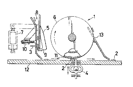
Figure 1 shows a side view of the apparatus in section,
Figure 2 shows an alternative form of the apparatus, like-
wise in a side view and in section, and Figure 3 shows the
roller according to Figure 2 in an isometric representation,
partially in section.
The apparatus has a guide (8) ~hich opens into a reversing
device (1), ~1a) for the test strips (2). ~etween the
guide (8) and the reversing device t1), (1a) is arranged a
closing means (9) for the guide. The clos;ng means (9) is
connected via a lever (5) to a holding device ~10), for
example a spring-loaded plunger for the test strips (2).
The holding device (10) projects into the guide (8) and is
mounted rotatably in synchronism with the closing means.
~hen the closing means (9) allows the test strip to pass
out of the guide (8), the following test strip is retained
in the guide by the holding device (10), until the guide
is closed again. The holding device and closing means are
equipped with a drive device (7). The reversing device
(1), (1a) has a moveable stop (4), (4a) which is driven by
means of the prepared pulses from a position-detection
means (3), for example a reflex-light barrier. The posi-
tion of the test zone on the test strip is fixed by
the position detection means (3). If it points in the
wrong direction, the stop prevents the test strip from
,: :

~32~1~9
being transported further to the analyzer tnot shown).
The test strip is reversed. Reversal can be carried out,
according to Figure 1, by means of a hollow roller (6) which
is evacuable and which has a leakage orifice (11). When
the test strip is stopped by th~e stop (4), it is sucked up
by the vacuum via the leakage orifice, held on the roller
periphery and reversed in the direction of the arrow as a
result of the rotation of the roller. The test strip is
taken off the roller by means of the stripper (13).
According to Figure 2, reversal is carried out by means of
a roller (6a) which is provided with a slot of T-shaped
cross-section parallel to its axis of rotation. The orifice
(15) is intended as a passage orifice in the roller (6a),
whilst the crosspiece (14) of the T-contour ends at the
stop (4a). When the position-detection means (3) signals
the correct position of the test strip, the test strip can
pass through the roller (6a) without obstruction. Other-
wise, it is stopped by the stop (4a) and reversed through
180 as a result of the rotation of the roller (6a). In
order to monitor the test-strip supply in the guide, the
~atter can be equipped with a monitoring device (16).
"

Representative Drawing
A single figure which represents the drawing illustrating the invention.
Administrative Status

2024-08-01:As part of the Next Generation Patents (NGP) transition, the Canadian Patents Database (CPD) now contains a more detailed Event History, which replicates the Event Log of our new back-office solution.

Please note that "Inactive:" events refers to events no longer in use in our new back-office solution.

For a clearer understanding of the status of the application/patent presented on this page, the site Disclaimer , as well as the definitions for Patent , Event History , Maintenance Fee  and Payment History  should be consulted.

Event History

Description Date
Inactive: IPC from MCD 2006-03-11
Inactive: Adhoc Request Documented 1996-08-10
Time Limit for Reversal Expired 1996-02-12
Letter Sent 1995-08-10
Grant by Issuance 1993-08-10

Abandonment History

There is no abandonment history.

Owners on Record

Note: Records showing the ownership history in alphabetical order.

Current Owners on Record
HOECHST AKTIENGESELLSCHAFT
Past Owners on Record
JURGEN GROSS
RUDIGER SIMONEK
Past Owners that do not appear in the "Owners on Record" listing will appear in other documentation within the application.
Documents

To view selected files, please enter reCAPTCHA code :


To view images, click a link in the Document Description column. To download the documents, select one or more checkboxes in the first column and then click the "Download Selected in PDF format (Zip Archive)" or the "Download Selected as Single PDF" button.

List of published and non-published patent-specific documents on the CPD .

If you have any difficulty accessing content, you can call the Client Service Centre at 1-866-997-1936 or send them an e-mail at CIPO Client Service Centre.


Document
Description 
Date
(yyyy-mm-dd) 
Number of pages   Size of Image (KB) 
Cover Page 1994-03-04 1 21
Abstract 1994-03-04 1 16
Drawings 1994-03-04 1 36
Claims 1994-03-04 1 31
Descriptions 1994-03-04 3 90
Representative drawing 2002-01-04 1 13
PCT Correspondence 1993-05-17 1 29
Prosecution correspondence 1990-09-07 2 54
Examiner Requisition 1990-05-08 1 43