Note: Descriptions are shown in the official language in which they were submitted.
~ ~ 2 ~
GA~ VAIVE
~ac~ground of the Invention
~ his invention relates to new and useful improvements
in gate valves of the t~pe having a wear and corrosion re-
sistant lining.
Gate valves are in common use for controlling flow mediasuch as slurries and corrosive fluids. ~hese valves have a
flow passage therein controlled by a plate-like gate slidable
in a recess in the liner. Gate valves often are used to con-
trol f`low of slurries or corrosive fluids containing abrasivesolids and are lined with a resilient, tough wearing and
corrosion resistant material such as polyurethane or poiy-
eth~lene. ~ow pressure gate valves are readily sealed,
namely, by the closing thrust of the gate and by a sealed fit
in liners or seals- High pressure valves on the other hand
create more problems in that sealing is more difficult and
high pressures can bend the gate at its lower end. When
there is side backing support for the gate to reinforce it
against high pressure, a large amount of friction may exist
~or opening and closing he gate. Also, side supports on any
gate, whether in low or high pressure systems, create pockets
or obstructions which can hinder the free flow of material.
~or best performance and all around functioning, it is de-
sired (1) that the structure of the gate valve when open
provide no obstruction through the flow passage so that there
will be efficient flow and minimum wear; (2) that the gate
have a good sealing function in the valve body for both low
and high pressure flo~; (3) that the eate have backing
,:,. ' ' '
, -
... . . ..
~ 321187
support at its lower portion so that high pressure conditions
in the fluid, preferably from either direction, do not damage
the gate; and (4) that the friction of gate movement be low
enough so that the gate can be readily opened and closed. It
is also desired that particles in the fluid do not gather in
the valve to the extent that they jam the gate. This
combination of structural features has not been fully achieved
heretofore.
Considering prior patented structures, for example,
10 reference is made to U.S. Patent Nos. 2,851,051 (9/58) and
4,603,864 (8/86~. Although no doubt effective to an extent in
their operation, portions of the gate seal form obstructions
in the flow passage and thus minimiz~ efficient fluid flow.
Also, heavy particles can jam at the seal and abrasive
slurries will cause undue wear. Structure shown in U.S.
Patent No. 4,112,969 (9/78) has a flow passage in the body
member which is unobstructed, but use with high pressure is
not possible because there is no backing support for the gate
at a lower portion thereof and the gate will warp under such
2d pressure.
U.S. Patent Nos. 2,669,416 (2/54) and 4,201,365 (5/80)
provide backing and/or sealing support for the gate but in
order to do this such support or sealing means form an
obstruction in the flow passage flow. Also, backing support
in these patented structures is only effective in one
.. ..
- - ' . ~
.. . . .
, : ,~ ,
~3211~7
direction of flow. U.S. Patent Nos. 3,784,158 (1/74),
3,897,043 (7/75), 4,377,274 (3/83), 4,522,224 (6/85), and
4,693,447 (9t87) employ gate valve seals that use a groove
associated with the sealing end of the gate for accomplishing
" . .
,, , ~
1321187
the sealing function. This type of grooved structure has
the disadvantage of allowing particles to collect therein
and hinder opening and closing of the gate and proper seat-
ing.
Summary of the Invention
According to the present invention and forming primary
objectives thereof, a gate valve is provided that amounts
~ to a substantial improvement over existing valves in that it
has a structure that makes it highly versatile in use,
10 namely, its flow passage when open allows movement of flow
media therethrough without obstruction in the area adjacent
the bottom of the flow passageway, thus permitting efficient
flow with minimum wear, that provides an effective seal in
both directions and at both low and high pressures; that has
15 suitable backing support for the gate to prevent damage to
the gate from high pressures; and that has a liner and gate
construction such that the gate can be readily opened and
closed without excessive locking friction and interference
from heavy material which may settle out of the flow media.
¦ 20 In carrying out the objectives of the invention, the
gate valve of the invention comprises a body having an
opening to which is bonded a plastic liner defining a flow
! passage through the valve. ~he plastic liner has a bottom
seating surface engageable by the bottom edge of a plate-
25 like gate slidable in a top opening recess. As an important
feature of the invention, the recess and gate are wider
than the flow passage and the gate receiving recess extends
to a point adjacent a lower portion of the gate and at least
~ ,,,,: . -
1321~ ~7
to a point below the horizontal center line of the flow
passage, for providing side sealing and backing
support for the lower end of the gate to prevent damage
to the gate from high pressures. That is, the side re-
cesses extend down and join with the bottom seatingsurface at a point between the center of the seating surface
and the side thereof whereby a seal is formed at the
bottom by the thrust of the gate valve and the sealing
transfers to the side recesses under the influence of
10 the line pressure. Backing support for the gate from line
pressure is provided in both directions. Further yet, the
lower portion of the flow passage defined by the liner com-
prises a smooth, uninterrupted opening devoid of obstruc-
tions. Upper portions of the recess are relieved for mini-
15 mizing opening and closing friction of the gate.
The invention will be better understood and additional
objects and advantages will become apparent from the
following description taken in connection with the accom-
panying drawings.
~rief Description of the Drawings
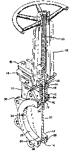
Figure 1 is an isometric cutaway view of the present
gate valve.
Figure 2 is a fragmentary face view of the valve with
a portion thereof being broken away.
Figure 3 is a verticl sectional view taken similar to
the cutaway view of Figure 1, and
Figures 4 and 5 are fragmentary enlarged sectional
views taken on the lines 4-4 and 5-5 of Figure 2.
13211g7
Detailed Description of a Preferred Embodiment
With particular reference to the drawings, the gate
valve of the invention comprises a metal valve body 10 and
an inner plastic liner 12. ~iner 12 can be co~structed of a
5 tough resilient plastic such as polyurethane, polyethylene,
or other plastic type materia:L which as is well known has
good resistance to abrasion and/or corrosion. Although valve
body 10 can be constructed of two or more pieces and
assembled while bonding or otherwise securing the liner to
lO it, it preferably is cast or otherwise formed as a single
member. In this instance liner 12 is injection molded to
the metal body. Yalve body 10 has a lower annular portion
14 and a flanged upper extension 16 that supports upright
standards 18 of operating mechanism 20 for a thin plate-like
l~ gate 22 for controlled flow of liquid.
Iiner 12 is U-shaped in cross section and in its in-
tegration with the body member defines a flow passage or port
24. It is U-shaped in cross section in this lower portion
and forms a smooth longitudinal flow-passage surface 26. ~he
20 right angle portions 28 thereof have vertical outwardly
directed smooth surfaces arranged for bolted and sealed
connection between radially projecting ears 30 and 32 on the
valve bod;y 10 and conduits 34, respectively, ~?igure 3.
Yalve body 10 has a top opening slot 40 in its upper
25 extension 16, and such slot receives in bonded relation an
upper integral extension 42 of liner 12. Slot 40 has an
offset portion 44 in which an offset portion 46 of the liner
.. :, : .
.
., j. . ,
. : ~ : . .,
~: ,
: .- . - ~ . . . : .: .
132i~ 87
is bonded. Offset portion 46 encloses seals 48 o~ a
stuffing box 50. The liner has a top opening gate-receiving
recess 54 in which the gate slides.
As an important concept of the invention, the valve
body 10, liner 12 and gate 22 have a particular and novel
structure contributing to the performance of the objectives
named herein. With particular reference to ~igure 2, the
slot 40 in the valve body is defined by vertical side wall
portions 40a and downwardly angled straight portions
40b leading from the lower end of the side wall portions 40a
at a point considerably below the horizontal center line of
the flow pàssage 24. Downwardly angled portions 40b lead
into a central rounded portion 40c. ~he lateral distance
between the side wall portions 40a of slot 40 is
substantially wider than the width of the flow passage 24.
lhe recess 54 in the liner 12 which slidably receives
~he gate is shaped laterally similar to the slot 40 in the
valve bod~, namely it is defined by side wall portions
54a, downwardly angled straight portions 54b, and a
connecting central rounded portion 54c.
Gate 22 is contoured laterally precisely the same as the
liner recess 54, namely, it has side edges 22a leading along
the slot edges 54a, downwardly angled straight bottom
edges 22b leading along and arranged to abut angled recess
2~ portions 54b, and a central rounded portion 22c extending
between angled portions 54b and arranged to abut bottom
rounded liner portion 54c. ~he rounded edge portion 22c of
the gate has side bevels 56.
: . :
. ' , .
'
~ 32~187
In view of the identical shape of the bottom edges 22b
and 22c of the gate and the adjacent liner seating surfaces
54b and 54c, respectively, the gata has sealing engagement
with the liner in these areaæ ~hen forced down by the gate
actuating mechanism. As best seen in ~igures 2 and 4, the
liner is wider than the flow passage 24 and its gate re-
ceiving recess 54 thus provides substantial gate confinement
at the sides and more particularly a confinement that
leads downwardly to a juncture point 62 in the flow passage,
for example, a point inwardly from the sides on the straight
wall portion 54b of the recess 54. ~he junctures 62
comprise points at which the recess wall portions 54 are
tangentially disposed relative to the flow passage 24 and
importantly considerably lower than the horizontal center
1~ line of the flow passage.
Opposite faces of the gate have a slidable sealing fit
in recess 54, and to reduce opening and closing friction
between the gate 22 and the recess, and to assist seating in
the upper portion of the valve, the recess has an upper
relief portion 64 extending across the gate recess down to
lower points 66 located a short distance above the horizontal
center line of the flow passage. ~his relief portion extends
along a defining arc 68 thereof disposed a short distance
radially outward from the flow passage to maintain a narrow
2~ sealing strip 70 of the recess 54 for the gate at this upper
portion. A short segment 72 of the recess 54 at the top is
not relieved whereby such upwardl;y extending wall portions
formed thereb;y serve as a guide for the gate when it is in
., . . ~
l 321187
its fully open position, as shown fragmentarily in broken
lines in ~igure 2. As also seen in ~igure 2, recess 54 is
of a width to provide clearance at the sides of the gate to
also contribute to ease of opening and closing.
In operation, the gate is movable up and down in its
recess 54 for controlling the flow of fluid through the flow
passage 24. The gate has face surface sealing engagement
with confining wall portions of the recess 54 starting
upwardly from juncture points 62. This sealing extends along
the sides to points ~6 and then along the arcuate strip 70
around the upper portion of the flow passage. The bottom
edge of the gate seals against the surfaces 54b and 54c of
the liner by the thrust of the gate actuating mechanism and
the sealing in the other areas is accomplished by a close
tolerance fit of the gate in the recess and by line pressure
on the upstream side. The narrow sealing strip 70 causes
good sealing on the downstream side dùe to higher seating
stress between the gate and this narrow strip.
Since the gate has face sealing engagement with the
liner along its sides and partially along a bottom
edge and also since engagement thereof ln the recess is
substantially below the center line of the flow passage,
the gate has backing support on the downstream side against
high pressure that may exist in the flow passage. More
particularly, the side recesses extend down and join with
the bottom seating surface at points 62 between the center
of the seating surface and the sides and a seal is formed
1321~g7
at the bottom by the thrust of the gate and by a sealing
that transfers to the side recesses under the influence
of line pressure. The gate thus cannot bend. ~he structure
accomplishes the same function in either direction of flow
and thus is unidirectional. The backing support for the gate
is radially beyond the plane of the flow passage and thus
there are no protrusions within the port that can hinder
flow and induce wear.
The valve is self-clearin~ since any solid particles
10 that may lodge in the side gate confining areas will fall or
be pushed by the gate down to the lower ends of these areas
and then flushed out. Straight wall portion 54b is sloped
sufficiently, such as approximately 45 , to allow material
deposited by the flow media in the recess above juncture
15 point 62 to slide down below such juncture point and out
of the recess to allow proper seating when the gate is
closed. If any fluid or solid particles escape upwardly
past the sealing portion 70, they will collect in the relief
portion 64. Such fluid or particles will fall down into the
20 flow passage the next time the gate is opened.
Thus, the present invention comprises a highly versa-
tile valve, namely, it is bidirectional and can be used in
low or high pressure systems. Also, the flow passage and the
gate is unobstructed by any type of gate backing support or
25 seals, and efficient flow is accomplished. Also, the liner
has long wear. The gate has minimum friction engagement
with the liner and is readily raised and lower.
It is to be understood that the form of my invention
... .
, ~ .
: . : ; . . . :,. : -
.. . .. .
13211~7
herein shown and described is to be taken as a preferred
example of the same and that various changes in the shape,
size and arrangement o~ parts may be resorted to without
departing from the spirit of my invention, or the scope
of the subjoined claims.
Having thus described my invention, I claim:
1 0
~'