Note: Descriptions are shown in the official language in which they were submitted.
~32~ ~22
IMPROVED SAMPLED SERVO CODE FORMAT
AND SYSTEM:E`OR A DIS~ DRIVE
Backaround of the Invention
1. Field of the Invention
This invention relates to improvements in disc memory
drives and, more particularly, to improvements in system and
methods and sampled servo code formats for a magnetic disc
drive.
2. Description of the Prior Art
Magnetic disc storaye ~ystems, called disc drives,
provide large volumns of accessible memory. ~hese conventionally
comprise a stack of me~ory discs mounted in axially spaced posi-
tions on a common spindle to be rotated at constan~ speed. The
disc~ have data recorded in concentric circular tracks on each
disc surface. Corresponding tracks on the disc surfaces are
cylindrically aligned. Magnetic heads on a moveable carriage,
there being one head for each disc surface, are radially and
circumferentially aligned, to be moved as a group to position a
selected head at a s~lected track ~or reading or writing at that
track locativn.
The track~ are each divided into equal radially aligned
sectors, aligned from disc to di~c. ~ach sector has a servo code
recording at its beginning, read by the magnetic head for use by
the ~ervo in driving the carriage and head for track following
and ~rack seeking operations.
The U. S. Patent to Lewis et al, 4,424,543 provides
2 ~ 3
. : : :
. :. -, . : ~ .:
,
. ' ~;. , ~, , :~ .
,
-"` 132~22
prerecorded s~rYo data in a section at the beginning of each
sector in each track, which comprises the sequence of an erase
gap, a preamble, a sector mark, a track nu~ber, a check code, and
a track position code. User data follows tho~ sector at each
track. The erase gap ~unction is to provide a time synchroniza-
tion. The preamble provides clock synchronization. The sector
mark is used as an addition~l verification of servo timing. The
track num~ers ar~ us@d for track s~e~ing. The checX code is usad
to check for clock hi~t.. The track position code is used for
track cen~ering. The code tran~itions in the track position code
are written to equ~lly ov~rlap ad~acent tra~k~ and to be offset
in time. When a head is on track c~nter, the signals from
transitions on one side o~ ~he track are equal to the signals
~rom the transition~ on th~ other ~ide o~ the track, which is
recognized by the servo as ~ track centQred condition. The track
position code i~ th~ only 5~rYO cod~ written to overlap adjacent
tracks.
In providing th~ d~crib~d $QrVO code ~or~at, Lewis et
al, are concerned wi~h provlsion~ ~or accura~ely transducing the
servo eode, ~or d~t~cting tim~ ~hl~t errors and ~or minimizing
the possibility of data overwrite into th~ embedd~d servo code,
as discu3s~d ~ith re#pect to Fig. 2. Th~ disclo~ur~ conc~ntrat~s
on ~r~X id~ntiricatlon an~ a clock shi~t. Nothing is said about
pro~ision~ for auto~atic gain control.
The U. S. Patent ~o P~nniman, 4,S30,019 also provides
prerecorde~ s~rvo da~a in a ~ec~ion at the beginning of each
:
... ..
sector in each track, which comprises the sequence o~ an erase
gap, an automatic gain control ~ield and A h B bursts o~ servo
control infor~ation for track cenl:ering purposes. Automatic gain
control i5 de~cribed as follow~;: "Inclusion of the AGC circuits
(not illustrated) allows the AGC burst of tha pattern to be
monitored and retained for use to ad~ust t:he gain of the
circuitry used to process the head transducer output of servo
information and al~o da~a to acco~nodate variations in the disk
storage media. This is particularly u~;eful to provide noise
i~Dmuni~y if the di~k iY to be read by a disc drive c: ther than the
one on which i~ was creatQd". Nothing fur~her is said about
automatic gain control, ~pecially ~GC codQ formatting, or the
details of a sys~e~ ~or proces ing and using signals ~rom the AGC
f ield .
Acceptable s~rvo ~y~teDI function in a disc dxive
re~uire~ c:are~ul control o~ ~ignal gain~ Although Penniman men-
tions automatic gain ~:on~rol, and i'c~ u~e, a~ noted above, the
thrust o~ hi~ toaching for a control for ~h~ rins~ positioning~ of a
transduc~r h~ad o~ a di~c driv~a unit res~ upon the ~ tablish-
ment of tiD~e~ rs~rence~ bas~d on ~hl2 ~ransition be~ween the
~rased gap and ~n AGI:: bur~t tog~th~r with a 8~rvo code decoding
t~c:hnique for fine posi~ioning o~E th~ ~ran~ducer head. ~either
Psnniman nor Lewi~ et al l~r~at au~omatic g2lin con~rol as a ~ac~or
requiring attention.
' ~ . ' . :
.
-
1~2~ ~2
Th~ present invention provide~ i~nprovement over the
U.S. pa~ents to Lewis et al and Penniman, in servo gain control,
in one of its aspects, in the provision of a servo code format
having an automatic gain control ~ield for con~rolling servo gain
variations, which may vary from head to head, from track to track
and from track sector to track s~ctor. Provisions for servo gain
control are necessary to provide relatively unifo~m servo gain,
at least in the circumstances described, if acceptable servo
performance is to be achieved.
In practîcing this invention, according to this one of
its aspects, a memory disc i~ divided into equal sectors. Each
sector comprises a section of servo code called a servo gap which
is locat~d at the beginning of the sector. The servo gap is
divided into sections which comprise, proceeding from its leading
edge, an automatic gain control section, a sector marX section, a
gray code track number section and a track position section.
The ~our na~ed section~ in the servo gap are
individually defined by magnetic dibit recordings in predeter-
mined patterns. The e magnetic dibit~ are also known as magnetic
transitions or magnetic ~ones. The surface O:e the magnetic d.isc
is magneti7ed uniformly in one direction. The dibits are magneti~
cally poled in the opposite direction, providing a transition in
the magnetic field at the leading and trailing dibit edges during
scanning by a magnetic head~
Th~ magnetic dibits have a width m~asured across the
' : ;
:;
'' ; ' ~ '~
1 3 2 .L ~ 2 2
tracks approximatsly equal to one-half o~ a track. All of the
magnetic dibits in th~ servo gap are the same and are recorded in
half track positions on each ~ide of the cen~er line of ~ach of
the tracks. They are written or recorded in half-track steps with
a magnetic head having a width o~ two dibits, which corresponds
to the width of a data track. Their patterns, when scanned in a
direction along the tracks, det~r~ine the information which is
recorded and which will be ~en~ed by a magnetic head scanninq the
track. Using this recording track technique the center line of
a track is defined between the confronting ends (aligned)or the
ad~acent ends (A&B servo field) of the magnetic dibits in half-
track positions on each side of each track.
The ~agnetic dibits on on~ ~ide of alternate trac~s are
consist~ntly re~erred to a~ the A dibits and the magnetic dibits
on th~ other side o~ the alternat~ track~ are consistently
referred to as th~ ~ dibit~. The~e ar~ r~versed on the tracks
inter~2diate to ~h~ alt~rnate ~rack~. Thi~ radially aiigns the
adjac~nt A and B ~agn~tic dibi~ Tha dif~erencQ of the A and B
signals developed in a ~agne~ic head which is ~canning a track in
the track po~ on ~ection of ~h~ ~ervo gap, is used by the 5ervo
to position that magne~ic head a~ track center. ~he sum o~ ~he A
and B signal~ d~velop~d in a ~agnetic h~ad is used ~or servo gain
compensation purpo~es, during bo~h r~ading and writing ~odes o~
disc driv@ use. Th~ guard band~ are provida~ a~ the leading and
trailing edge~ of th~ 8erVo g~p to provide space for preven~ing
overwri~ing o~ da~a into ~he ~ervo gap a~ ~he l~ding ~dg~ and,
1 321~L22
at the trailing edge to switch the head from a mode providing
si~nals ~o the servo to a mode providing for reading or writing
of data code.
The signals derived from the automatic gain control
field are peak detected in a fast set~ling AGC loop and
normalized a~ to amplitude as a step in ~aintaining substantially
uniform servo gain. this as an i~portant fsature for reliably
reading of the servo cod~ especially the sector mark which fol
lows. Detection of the sector mark e~tablishe~ an exac~ kiming
re~erence with the trark nu~ber and track position servo code
that follow it.
The sector mark signal~ are thre~hold detected at about
one-half the level of the peaX detection of the AGC signals. The
sector mark pattern is designed to be fault tol0rant and is read
in three parts, called space 1, spaee 2, and space 3, using bit
count2rs and an algorithum providing ~or ~it count testing in
each sector marX space. By thi~ expedient, positive recognition
of a sector mark ic assured.
Track identification is provided using track numbers
recorded in ~ray code. The ~ray code is also recorded using the
half-track dibit r~cording technique. The track numbex signals
are threshold det~cted an~ used in track seeking operations as a
feedback siqnal to the ~ervo which i5 responding to a requested
track number. This eliminate~ t~e need for seeking inner and
out~r track guard bands as a referenc~ for track counting
, . : ,
~' '' ~ ', .
: .
2 2
purposes .
Track position servo code, also rec:orded using the
hal~-track dibit racording technique, follows the track number
code in the servo gap. Th~ A dibit~ ar~ recorcled on one side of
each track and the ~ dibit3 ar~ record~d on th~! opposite side of
each track. Due to the hal~-track recording technlqu~ the A and B
dibits swap track ~ide~ and are ra~ially aligned in adjacent
half-track posi~ion ~ Th~e are formatted in two different mag-
netic dibi~ patterns. ~n on~ p~ttern, the individual A and B
dibit~ al~r~ate in circ~m~r~ntlal pha~ position on opposl~e
~ides of the track~. In th~ othQr pat~ern, th~ A dibit~ are
recorded in groups o~ dibit string~ or burst~ on one side of each
track an~ the B ~ibits are recordsd in group~ o~ dibit strings or
bursts on th~ other ~ide o~ ea~h ~rack. Th~ A an~ B di~i~ groups
alternate in circum~er~ntial pha~e po~ition on oppo~it~ side~ of
the ~racks. When a head i~ track cent~red over the Srack posi-
tion servo code, th~ A and ~ signal a~plitude~ are equal. The A
and B signal~ ar~ procs~ed in an AGC loop coupled to a sexvo for
providing servo control ~ignal~ which ~aintain servo gain
substanti~lly unifo~. Th~ di~er~nc~ in the pro~essed A and B
signals i~ u~d by th~ s~rvo ~or track ~ollowing purpo~es.
:.
`- ~32~ ~22
Various aspects of t~e invention are as follows:
In a magnetic disc drive, the improvement
comprising:
a. a rotatable magnetic memory disc haviny a
plurality o~ concentric circular tracks which
are each divided into sectors, each sector
being radially aligned with sectors in
adjacent tracks, each sector having a servo
gap which is radially aligned with 5ervo gaps
in adjacent tracks in that sector; and
b. an automatic gain control filed in each servo
gap, having magnetic dibits which have a
radial length less than one-hal~ of the
distance between the centers of adjacent
tracks, disposed in uniformly circum-
ferentially spaced positions, in radially
spaced, end-to-end alignment with each other,
in half-track positions on each side of the
center of the tracks; whereby a magnetic head
traversing the automatic gain control field,
overlaps substantially the same amount o~
magnetic dibit, whether or not positioned at
the center o~ a track.
In a magnetic disc drive having a magnetic memory
disc provided with a plurality of concentric circular
tracks which are divided into sector~, the method for
magnetic dibit recording of separate magnetic dibit
fields for forming a servo gap in each sector,
comprising: .
a. providing a magnetic head having a width
corresponding to the width of track; and
b. recording with said magnetic head separate
magnetic dibit fields in half-track radial
steps~ placing pairs o~ said magnetic dibits
in sel~cted circumferentially spaced
8a
. " , .
.. . . ... . . ...
32~2~
positions, in radial halfrtrack alignment in
positions between track centers.
Xn a magnetic disc drive/ the improvement
comprising:
a. a magnetic memory disc having a plurality of
circular tracks thereon, each circular track
having a servo gap therein disposed in rad,al
alignment with servo gaps in adjacent trac}cs;
b. an automatic yain control field and a track
position servo field in circumerentially
spaced positions in each servo gap and
respectively, radially aligned with automatic
gain control fields and track position servo
fi.elds in adjacent tracks; and
c. pairs of half-track magnetic dibits disposed
in selected circumferential positions, in
radially aligned, spaced end-to-end positions
disposed betw~en and spaced from adjacant
track centers in both said automatic gain
control field and said track position servo
field.
Brie~ Description of th~ Drawinqs
Figure 1 is a partial map of the surface of a
memory disc.
Figure 2 is a plan view of a s~ctor of a memory
disc,
8b
: -~. .;
, ~ ,
132~22
fragmentarily illustrating magnetically recorded tracks.
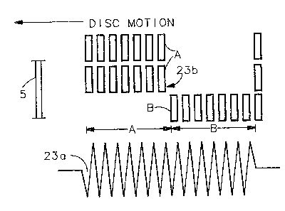
Figure 3a is an enlarg~d plan view of a ~ragment of the
magnetic 20nes or dibits of one format of a sampled track posi-
tion servo code d2fining a track and a typical processed, track
centered, track following signal which is shown therebelow.
Figure 3b is similar to Figure 3a, illustrating a
presently preferred format o~ a sampled, track position .~ervo
cod~.
Figure 4 is a rectilinear enlargement of the servo gap
portion of one disc sctor, illustrating the Pormatting of the
servo code magnetic dibits and idealized signals derived
there~rom.
Figure 5 i~ similar to Figure 4, illustrating a
presently pre~erred track position servo code for~at in the servo
gap (The A and ~ dibit group&);
Fi~ure 6a and 6b illustrate th~ relationship of timing
signals, with th~ idealized servo code siynal~ of Figures 4 & 5,
respectively;
Figure 7 i~ a block diagram of an automatic gain
control circuit;
Figure 8 is a block diagram of a position error cir-
cuit; and
Fi~ure 9 is a ~low chart illustrating the ~teps in
d~tecting the sector mark in the servo gap.
- . :, .: .
,. . .
2~22
P~c~,p,tion_o~h~y ~imen~
Figure 1 illustrates the e~sential parts of a disc
drive for pres~nt purposes, co~npri~ing a disc 1, a pivotally
mounted armstack or carriage 3 ~nd a ~agnetic h~ad 5 on the end
of a flexure assembly 7 which i~ attach~d to tAe end of the
armstack or carriage 3. A. di~c drive typic:ally includes a
plurali~y of disc~ 1 which are axially spaced on a spindle and
rotated in a counte:r clockwise dirQction, as view~d, at constan
speed. Magn~tic hç~ad~ 5 ar,s E30si~ioned on ~ach ~ide o each disc
by the carriag~ 3 and the flexurs a~se~bly 7. The carriage 3 may
be part of ~ither a linear or a rotary actuator ~yste~ for moving
th~ head~ across th~ di~c to ~if~e~rent track pot3itions. A
rotatably mounted ~21rriag~ hown having a pivot moun~ 9. An
actuator member 11 compri~es a fixe~l, arcua~e magne~ structure
13 nd a coil 15 on one e~nd o~ th~ carriag~ 3 which is Iaagneti-
cally coupled to the~ ~agnQt. In th~ E~ervo ~od~ o~ operation,
for either track s~Q~k~ng or tras:k Pollowing pUrpO~B, a servo
system 16 i~ conn~ct~d ~o a ~ ct~d ~nagne~ic hea~ 5 to receive
signals therefrom for thQ pUrpo8~ OL'' controlling thQ actua~or
member 11 to which th6~ output o~ th4~ ~ervo i~3 connected. A host
computer 14 proYide~ r~ ts~ l~o ~he sQrvo ~y3te~, such as track
mambers, in acc~sing in~EorDIa~ion in the di~3c drive ~or computing
or data proc:e~sing ~unction~.
Th~ improv~d ~srmatting o~ ~he ~ ro code in ~h~ memory
di~c is uReful in ~a~apl~3d ~nro ~yst~m~ o~ th~ type described in
co-pending Canadian appl`ication serial no. 542,292 enti~led "Method And
- . , .
2 ~
Apparatus For An Improved Sa~pled Servo Seek ~nd Track Follow
Diqc Drive", a~signed to the assignee
of this invention. As described in that application, proper
formatting of the servo cod~ on the di~c, including th~ use of
track numbers to identify individual tracks, obviatas the need
for a dedicated servo di~c. This reduces ~yste~ complexity, in
that ~witching of the ~ervo between prQsent, dedicat@d, and
target h~ads i~ eli~ina~ed, a~ong other rea~on~.
The disc 1 i~ d~vided into a plurality of sectors 17
which are equal in 3iZ~. Only a f2w o~ ~he~ sectors are
illustrat~d for present purpo~a3, ona b~ing detailed. Each sac-
tor 17 comprise~ a s~rvo gap 19. Th~ ~rvo gaps 19 a~o~iated
with individual concen~ric circular track~ 21 are radially
aligned, a~ shown. The ~ction o~ ~ach track extending through a
servo gap has servo cod~ record~d th~xein. The section of each
track ~ollowing its ~rvo gap in a particular sector ha~ data
recorded th~rein u~ful in d~a processing func~ion~ or in
computer function~.
Figur~ 2 i~ a furth~r ~velop~nt o~ Figur~ rawn to
an ænlarg~d scal~, illu~trating additional detail~. Only two
concentric tracks are ~hown. ~nlarg~m~nt p~r~it~ ~howing
additional detail3 of thQ s~rvo ~od~ in a ~ervo gap 19 as ~een in
tha serYo gap on ~h~ right in Figur~ 2. Th~ ~ervo code is
recorded along track sQction~ 2la ln a s~rvo gap, and comprises a
trac~ positîon ~ervo cod~ ~ection ~3, a ~rac~ nu~b~r sec~ion 25,
~32:~2~
and a section 27 co~npri~ing primarily an area o~ auto~atic gain
control with a sn~all guard band GB1 (not shown here) at the
front. Two types of track po~;ition ~3ervo code are described in
thi~ disclosure. The track position s2rVo code shown here
co~prises magnetic zone~ or dibits A and B in circumferentially
spaced position~ on oppo~ite ~ide~3 of the track center 1 ine,
over}appin~ roughly one-hal~ o~ a track on each ~ide oî a track
cen~er line 21a. The Dlagnetic dibit~ B are in circumferential
positions in~er~nQdiat~ the!~ grletic dibit~ A, ~hat is, they
alternate in circu~nferential pha~ position. The magnetic dibits
in the saction 25 defining the trac:k nu~er~3 are al~o recorded in
hal~-track position~ on 6~ach side o~ ~ traclc c0nter lin~a 21a, as
ar~ the magnEatic dibit r~cording~ ln th~ au~o~tic gain control
section 27. When the disc~ rotate, trac:k po~ition signals are
developed in the s~l~actecq magne~ic head when ~che dibit~ of the
~rack po~ition ser~ro cod~ 23 pa~ therab~rleath~ These signals are
useful in dater~ining th~ radial po~itlon o~' th~ ~agnetic head in
relation ~o t~ agnQtic zon~ or d~bi1:~ ~ and B and, hence,
track center.
Fi3ura 3a i~ an enlarged view o' a modified fra~nent
o~ ~he track poaition 9~trV0 code 23 o~ ~igure 2, as will be
d~veloped in Fig. 4. ~ ~agnQtic head 5 i~ ~hown on the left in
thi~ figur~ in track c~ratl3r~d po~i~ion. Th~ ~ur'ac~ of the disc,
repr~nted in th~ plan6!~ o~ the drawing, i8 0~ ona magnetic
polarity. Th~ mzl~tic: zon~ or dibit~ ar~ o~. the oppo~ite
magnetic polarity. DiSc rr~tion fran rignt to l~ft, as viewed,
12
,
` , ' ' '
- :~32~22
beneath the ma~netic head 5, generate~ track position servo cod,~
voltages in tha magne~ic head, which af~er amplification and
processing, are charack~rized by the tims varyi.ng track position
servo code wave~orm~ A and B shown in Figure 3a. The di~ference
between the A and B dibits volta~es (A-~), which is inl:egrated ,
indicates the radial po:~ition o~ the magnetic head with respect
to the ~raGk center and is used in t~e tra ~c fol}owing mode of
operation for keeping ~h~ magne~ic head track-centeredO When the
differen::e b~twe~n the A and B ~ignal~ i~ z~ro, ~he Dlagnetic h~ad
~ rack-c~n~red~ Th~ u~ of th~a ~ignal~ ~ and B in track
following and in track s~eking op~ration3 in a sampled se~ro type
of track 3seking and tr2~clc following ~ervo ~ystam, i~ de~cribed
hereina~ter. Such use i~ also dQ~crib2d in the referenced co-
pending applica~ion, above.
Othar way~ in which thes~ A and B signals ar~ usPd in
track seeking and ~xack following op~r~tion3 are known in the
prior art. S~e thQ pa~n~ to ~wi~ Qt al and ~nnin~an, above.
Figur~ 3b illustra~e~ a presently preferred tra~k poci-
tion 5e~0 cod~ ~or~at.. The A and B magnetic dibits are again
recorded in halr-tr~ck po~itions, but now they are in strings or
bursts coDIpri~ing, gor exa~ple, ~tring~3 oP seven dibit~ in alter-
nating circu~îar~n~ial phs~3~ po3i~ion~3 on oppo~it~ sides of the
track. ThQ ~ignal wav~or~ sJenera~d wh~n the magnetic h~ad 5
scan thi~3 di~ onna~ has ~he s~e appearance a~ that of Fig.
3a, bu~ ~he in~i~.ridual wav~or~ pe~ak~s, ins3~e~d o re~ulting from
,
. :" j;
the alternate sensing of the A and B dibits, now results from
alternate sensing of A and B dibit strings or bursts, resulting
in waveform group A and waveform group B. Here, again, the
difference between the A and B voltages indicates the radial
position of the magnetic head with respect to track c2nter.
Processing of the A and B voltage~ for bokh formats will be
described at a later point.
Figures 4 and 5 are enlarged, rectilinear developments
of servo gaps according to this invention, each showing
recordings of the magnetic dibit~ for 4 adjacent disc track~
which have been arbitxarily numberedr tracks three, four, five,
and six. Figure 4 ~hows the track position servo code format of
Fig. 3a and P'igure 5 shows the track position ~ervo code ~ormat
of Fig. 3b.
The direction of disc motion in each figure is indi-
cated at the top of the drawing. The radial and circumferential
directions with reepect to the disc are also indicated~
Additional in~ormation with respect to the servo gap i5 evident
in each figureO Proceeding from the leading edge of the servo
gap which is ~t th~ le~t ~ide of each figure, as indicated, each
servo gap comprises a first guard band, GB1, an automatic gain
control section or field, 27, a sector mark section or field, 29,
which is the same ~sr all sectors, an index bit, Il, a defect
bit, D, a track number ~ection, 25, recorded in Gray code, a
second index bit, I2, and the A and B track position servo code
field 23. Each servo gap ends with a guard b~nd section GB2.
1~
. -
~32~22
Data trarks appear on each side of the servv gaps. Eachillustrated servo gap i5 part of the sector ~hich include~ the
data tracks on the right of the S2rV0 gap.
Guard ~ands, ~Bl and GB2, are write splice areas that
account ~or disc rotational speed variations so that the servo
code is not overwritten by the user data. The guard band, GB1,
during a writa operation initiates the interruption of the
writing operation at its leading edge and, thereby prevents
overwriting into the AGC ~iald.
The automatic gain control fleld, 27, is de-tected (in
response -to the signals from the magnetic head) by a fast
settling auto~ati~ gain control loop, Fig. 7, that noxmalizes the
signal amplitud~s so that ~ub3~quent ~ervo gap fields can be
properly detec~ed and proc~ed. This is particularly impor~ant
if a h~ad switch has just occurred which could result in a signi-
ficant change in ~ignal a~plitud~. Th~ automatic gain control
field, 27, is also use~ ~or automatic gain control ~or data
detection circuit~.
In auto~atic gain control, the ~ignal amplitud~ is
normalized. Except ~or ~agn~ic dibi~ pat~exn differences (cir-
cumferential dibit ~pacing) for th~ purpose o~ identifying trac~
numbers~ ~ctor mark~ and track po~i~ion~, the au~oma~ic gain
con~rol field i~ recorded at sub~tan~ially ~he ~a~e density as
the Gray code and ~he ~ine s~rvo field (track position servo
code). In ~ran~ducing ~he~e magnetic fi~l~s, the Gray code
. . : .
~32~ ~22
field, for example, is transduced at half the voltage threshold
of the threshold used for the automatic gain control field, so
that detackion of the Gray code track number will change when the
magnetic head is half off-track.
The sector mark, 29, also detected at half the peak
voltage of the ASC field, is a special bit patt~rn that
establishes an exact timing reference with the servo signzlls that
~ollow it. This eliminateæ the need for a phase locked loop that
normally is used on dedicated servo disc drives or as in sampled
servo drives such as used in Lewis et al~ above. The sector
mark pattern (Figs. 6a and 6b~ is designed to be ~ault tolerant
so that it can be correctly id~ntified even in the presence of a
disc defect. It is also used to control disc rotational speed by
timing the interval between s~ctor marks.
Index bits, I1 and I2, are redundant bits used to
identify a ~ector called the index sector. Only one sector on
each track has transistions or dibits written into bit cells, Il
and I2. This is a sector zero, for example. The redundancy
provides immunity to disc defects and identifies a selected
sector as the initial sector on the disc from which other sector
locations are determined.
The defect bit, D, is a bit cell that has a dibit
written into it, if the next, or following, servo gap has been
determined to be def~ctive. This bit is written into the format
at the time of manufacture of the disc when the servo code is
being tested. Any servo gap which happens ~o contain a disc
16
~32~2~
defec~ can be marked defectiv~ by writing the bit D into the
previous servo gap. This bit informs thie servo demodulator
electronics to ignore the next 5ervo gap. The data field in the
sector associated with that servo gap can be processed nv.~ally.
The gray coded track numher section or field 25, is a
set of magne~ic dibits that contain the track address for the
track that the head is precently flying over. Thes~ are binary
addresses that are encoded into a Gray code sequence so that any
decoding uncertainty is limited to plus or .~inus one-half track.
In using Gray code, only one bit in the ~rack i~ntification
number changes from track to track, as shown. The txack addres-
ses are read and decoded even during a track seeking operation.
In fact, it is these track addre~ses that are used to provide
track position feedback to control the seek operation. In prac-
tice, a host computer may be employed to program ratrieval and
writing of information in the dis~ drive. In this respect, the
host comput~r 14 (Fig. 1) makes requests in the for~ of particu-
lar track number~ which are to be acce~s~d. The present track
address or number where ~he magnetic head is located provides
the feedbacX signal which is used in this se~k operation~
The track position servo code, 23, also called the A
and B fine servo fields, compri~es ma~netic dibit recordings that
are recorded in one-half track positions on each sid~ of the data
track center line. In Figure 4, the individual B dibit
recordings on one side of a track center line are circumferen-
17
: . . ~
:, :
::
.
: . .
~3~ ~2~
tially spaced in posi~ions which are intermediate the individualA dibit recording~ on the opposite ~ide of that track center
lina. In ~igure 5 ~he B groups or strings of dibit recordings
on one side of a track cent~rline are circumferentially spaced in
positions which are intermediate the A groups or strings of dibit
recordings on the oppo~ite 8id~ 0~ that track centerline. As
noted above, when th~ a~plitude~ o~ the processed A and B sig-
nals, developed by magneti~ h~ad transition of the track position
servo code are equal, ~hat magnetic head is axactly positioned
ovar the centerlin~ of ~hat parti~ular da~a tra~k. Thesa sign21s
ar~ u~ed to prcvide feQdback control ~or ~he s@rvo system 16 for
track following purposeq.
Th¢ u~e of the au~o~atic gain control section or field
in the servo gap provide~ a basis for dev~loping an inexpensive
servo sy~em. By placing the auto~atic gain control field in ~h~
fron~ of each 5ervo gap an~ by making ~he auto~atic gain control
response tim~ fa t enough to s~ttla within the period o~ time in
wh~ ch the automatic gain control field i~ scanned by the magnetic
head, the au~oma~ic gain control voltagQ can b~ det~mined. This
voltage, call~d a gain ad~ust~ant ~oltag~ her~in, is held ~ixed
until th~ n~xt sarvo gap i~ rsachecl and i3 u~ed to normalize the
amplitude~ o~ ~11 sign~ls ~rive~ fro~ ~ervo and data ~ode in the
sector containing that ~arvo gapS
Atten~ion i~ dir~c~d ~o th~ fac~ ~ha~ th~ magn~tic
dibits in all of ~h~ ~ctions or fi~ld~ wi~hin ~h~ s~rva gap are
the sa~ and are recorded in hal~-track posi~ion~ on each side of
1~
` ~32~ ~22
the ihdicated track, using a magnetic head twice the
width of a dibit and recording dibits in half-track
steps. The result is a magnetic field pattern, in the
automatic gain control field, as seen in Figs. 4 and 5,
between the centers of tracks numbered 3, 4, 5 and 6,
for example, in which; the magnetic dibits are radially
disposed of the tracks, have a radial length less than
one-half the distance between the centers of adjacent
tracks, are radially positioned in pairs in spaced end-
to-end relationship between and spaced from the centers
of adjacent tracks, and, on opposite sides of the
centers of the tracks are circumferentially spaced, to
form magnetic dibit ~ields of differing formats or
patterns. A magnetic head 5 in the automatic gain
control field due to the uniformity and density of the
dibit pattern sees the same amount of magnetic dibit
whether it is track csntered, whether it is off center
from a track, or whether it is involved in a track
seeking operation crossing tracks as it traverses the
AGC field. This solves the problem of achieving good
automatic gain control when the servo is being switched
from one magnetic head to another. By this half-track
recording technique in which the fields on ad~acent
tra~ks are written coherently, the magnetic head reads
properly even when it is in a position between the
tracks; thus, this arrangement also provides a proper
automatic gain control function during a seek operation.
This arrangement also avoids the problem of having
to settle the automatic gain control function during the
performance of a head switching operation, or seek
opexation, or both, at the same time that the heads are
trying to settle on a particular track. This prohlem
exists in systems in which the automatic gain control
and the position loops are interacting loops.
19
.
- . .
- ~ 3 ~ 2 ~
By formatting the automatic gain control field or
section, as indicated above, the servo signal formad by
summing A ~ B can be held constant or relatively
constant.
The signal train depicted at the hottom of each of
Figures 4 and 5 i5 idealized. Each shows the ampli.tude
of the
19a
. ~ . . ,, .~ , :
,: :.
: ., .
:~3~22
pattern of the ~ignals developed in the different ~ields or
sections o~ ~he servo gap as i~ is scanned by the magnetic head.
The signal patterns relate to the bottom track, called track
number 3. ~ track centered position of the magnetic head 5 is
shown but the signal pattern~ transduced from the AGC field are
valid for both on track and off-track positions. The peak ampli-
tudes of the signals are relatively constant in all sections. As
discussed abov~, it is desirable to detect the signal 25a,
representing a track number, at hal~ the peak amplitude of the
automatic gain contxol signals. By iso doing, ther~e is a
confidenc~ that existing signal bit~ will be counted and that
signal levels, where bits ar~ ~issing, will not be count2d. Also
the track number changes as th~ magnetic head crosse~ a half-
track position.
In the track position servo ~ield, the signal
amplitudes are relatively con~tant and they are roughly half the
peak amplitude of th~ ~ignals in the other servo fields; the
reason being that ln track centered po~itio~ the magnetic head 5
overlaps one-half o~ the dibits A and B at different times~
Figures 6a and 6b relate a set of timing signals to the
servo code ~ignals of ~igures 4 and 5, respecti~ely. These are
rectangular wave ~ignal~ that enable selected functions in tran~-
ducing the servo code. An enable signal EN(~GC) conkrols the
time interval in which the AGC field may be read~ As seen in
Figures 6a and 6b, a write recovery interval i5 provid~d as the
he~d enters the AGC field, followed by a read interval which
~ - , . . .
-' . ~.' ':~ ....
: . ' . ', ; :
- ~32~ ~2
~erminates at or within the end of the AGC field. The signals IA
and IB gate the A and B signals, individually, Fig. 6a, or in
groups, Fig. 6b, in sequenc~a for processing to form the signals
A-B and A+B, as will be de~crib~d. More particulaxly, in Figure
6a the signals IA an~ I23 are synchronized with the inclividual A
and B voltage peak~, respectively, In Figure 6b, the signals IA
and IB are synchroni2ed with the A and B signal groups and pro-
vide respQctive read intervals les3 than th~ re~pective inter-
vals o~ ~ha A and 8 E~ignal group~, to avoid signal loss~s at the
baginning and end of th2 individual 3ignal group~. The IA and IB
signals are gated by a sampl~d ~ervo galte signal SSGT w~len it is
in the lower o~ it3 two voltage stat~ disc:harge sign~l DSCG
is provided which, in th~ high~r o~ its two voltags states,
discharges individual integrating a~pli~iers to which the signals
A and B are gated, aR will be ~e~ ribe~d. Circuits for producing
thP timing signalR ar~ w~11 known, ~e~ l:h~ pa~ent to Lewis et al.
Provi-~ion for d~tecting a ~ec~or mark is de~cribed
herein. A~ ~een in Flgur~ ~b a ~ctor mark 35 bit~a long is
employed to illu~trato thi~ feature. Other bit 10ngths may be
us~d. The 3~ctor mark i~ divided into thrae xpace Space 1 a~
the be~inning o thQ sec~or ~ark i~ 5 bi~ long. Cer~tral space 2
is 25 bit~ long and en~ing spac~ 3 i~ 5 bi~s long. This bit
patt@rn ident~ ha~ a . ector maLrk and i~ u~ed in deter-
mining that the sector mark ha~3 been found, a~a will be seç3n in
the flow chart o~ Pisure 8.
- ~32~22
A fast settling AGC circuit ~or per~orming the auto-
matic gain control ~unction is illustrated in ;Figure 7. Here,
the electrical ou~put of the magnetic h~ad S ~raversing ~he servo
gap is amplified in a prea~pli~ier 31, the outpu~t o~ which is
coupled a~ on~ inpu~ to an au~omatic gain con~:rol amplifier 33.
The output of this amplifier i8 ~iltered by a filter circui~ 35,
the output of which is applied to an amplifier 37. The output
signals AN of the ampli~i@r 37 are peak d~tect~ by a peak detec-
tor 39, controllad by the anable AGC signal 40 ~ENAGC), the
output of which is diff~rentially co~pared with a re~erence AGC
signal having the de3ired amplitudx. ThQ di~fer~nce ~ignal ia
inte~rated by an integrat~r 43 which prod~ce~ and ~tore~ a gain
adjust signal coupled as ~2dback in the loop to the s~cond
input of the AGC ampli~ier 33. This gain adju~t signal exists
through out the scanning ~f th~ pr~ent ector which includes the
remainder o~ ~he ~ervo gap and ths data field. Ths AGC cycl
starts over again a~ th~ ~a~n~ic h~ad ~can~ the n~x~ A~C :eield
in the nex~ servo qap in ~h~ pr~nc~ o~ ~h~ 3ignal 40 (EN~GC)~
Th~ gain adju3~ f~edback signal func~ion~ either to
increase or decrea~ the ougpu~ of th~ ~C a~plifier 33 in a
sen~e to balance th~ p2ak amplitude output o~ the peak detector
with the p~ak ampli~ude~ o~ the re~erence AGC signal during the
~GC interval (ENAGC~ Thu~ in scanning the au~omatic gain
control field 27 ak the front end o~ th~ s~rvo gap, an au~omatic
g~in control ~unction i~ achiev~d~ When the sampled servo gating
~3~2~
signal SSGT is in the lower of its two voltage states, are
coupled to a position error signal demodulator ~5, Fig.8, in the
input o~ the servo system 16, Fig. 1, having its own A+B
automatic gain control ~unction. A read enable timing signal
REN, Fig. 6a, in the higher of its two voltage states, following
the sampled servo ~ating signal S~GT, enables a data circuit 38
as the magnetic head enters t~ data ~ield, which traMsmits data
to the user 42 as requested by the host computer 14.
The position error signal ds~odulator 45 of Figur~. 7
is i~lustrated .in block diagra~ ~or~ in Figur~ is a ~art of
the servo sy~tem 16 o~ Fig. 1. Th~ no~alize~ signals, AN, from the
automatic gain control a~pli~ler of Figure 7 ara coupled as ~he
servo signal input ~o a 8~rVo dibit current conYerter 47. This
current converter is gatsd ~y the sampl~d ~ervo gating signal
SSGT (s~e Figure~ 6a and 6b) ~o that only the A and B track
position servo code ~lg~al~ are proce~sed. The QU~pUt 0~ this
circuit 47 i8 a current I(DB) which i~ the dibit current
developed only fro~ th~ ~ and ~ 3i~nal~. Thi~ current i~ coupled
as an input to an AGC current divid~r 49 which ha~ a second input
V(AGC) coupled ~ro~ a ~e~back loop and a re~rence inpu~ VtR),
to achi~ve au~omatic gain con~rol. Its output current is
de~ignated I(~C). Th~ A and ~ curr~n~ signal~ I(AGC) ~ro~ ~he
A~C curren~ divider 49 are couple~ a~ input ~o a s~rvo dibit
integrat~r 51 which i5 qated by th~ signal~ IA and IB (se~ ~igure
~a and 6b), synchronously wi~ the A an~ B si~nal input. This
23
, ,
.. . ..
'"~ ' ' '~,' ' ~' ,, " :' '
, . . .
32:~2~
integrates ths signals from the ~ and B track po~ition ser~o
field~, producing the A level and B level output signals A(LVL)
and B(LVL). In practice, these signals are coupled to differen-
tial and summing ampli~iers which are here represented as
differential and summing circuits 53 and 55, respectively, for
producing the position error signal (A-B) and the sum signal
~A~). The position error signal (A-B~ is used in the track
following control loop of servo system 16 to control the actuator
11 of Figure 1, to posi~ion the head 5 on the center of a slelec-
ted track. The signal (A+~ compar~d with a refer~nce signal
(A&B REFERh~OE) in the circuit 57, the output of which iscoupled to an
integrating amplifier 59, whic:h provide~ the ~aedback V(AGC) tothe automatic gain control curr~nt divider 49.
The servo dibit current e~onver~r 47 provides the out-
put ::urrent I (DB), that i~ proportional tc~ the a~plitude of each
A and B input siynal. It function~ as a half-wave rectifier. In
thiR application it rocti~ only tl~e n~ga~ivç~ levels o~ ~he A
and B s~rvo signals to produc~ ~h~ curr~nt pul~es I(DE3).
Such a current coa v~rter may be impl~ent~d using a
cs~nventional PNP type ~:ransi~tor, which i~ ba~e }: iased so that it
is nonc:ondu::~ing or ~ antially nonconducting, and disabled by
an invert~r having an outpu~ roupl~d ~o the tran~isl:or emitter,
which norEally pull~ ~ha e~i~t~r voltag~ ~o a level below the
basQ bias volt~ge. In t~a presenc~ o~ th~s sa~npl~d servc3 ga~ing
signal SS&T, thQ invert:er cir ::ui~ permit~ th~ ter voltage to
rise so tha~ the ~ransi~tor can conduct . ~hQ A and B servo f ield
24
:, ~
,. - ~:
~1 3.53~ ~2
voltages are AC coupled into the base o~ the ~ransistor. The
negative excursions cause the transistor to conduct to produce
the current I(D~
An AGC current divider such as the circuit 49, may
include a differential pair of PN~ transisl:ors that divide the
incoming current ~(DB), and deliver some fraction oE it as the
output current I(AGC). Th~ amount of the input current, I(DB)
that is delivered as I~GC) is controlled by the difference
between the feedback voltage V(AGC~, and a re~erence voltaye
V(R). V(R) is established at a nominal value compatible wi~h the
syst2m.
The servo dibit integrater may comprise a PNP transis-
tor pair, in which the signal I(AGC) is coupled to both emitters
which are also clamped at a predetermined volkage. The collec-
tors are individually capacitor coupled to ground. Fixed biases
on the bases o~ these transistors bias them to cut off, or sub-
stantially to cut o~. The signals IA and IB are coupled,
respectively, to the transistor bases and switch the transistors
synchronously with th~ individual ~ and B voltages o~ Figur~ 6a,
or with the A and B voltaye groups o~ Figure 6b~ The A level and
B lev~l vQltages, A~LVL) and B(~VL), ar~ output buffered ~rom the
respective collector circuits of the transistors. The discharge
signal ~SC& controls individual switches in the collector cir-
cui~s ahead o~ the capacitors, to couple the capacitors to
ground, so that the capacitors may b~ discharged just prior to
., : . ~ ~ ; , ,
2 ~
the time of the magnetic head transistion of the track position
servo code.
The automatic gain control amplifier together with the
sum and difference circuits 55 and 57 sums the A(LVL) and B(LVL)
inputs to rreate the servo gain fac~or signal (A+B), which is
compared to an A+B re~erence signal in the input circuit 57 to
the integrater amplifier 59. The circuit 57 represents th~
positive and negative inputs to the integrater ampli~ier. The
output voltage V(AGC) adjusts itself to whatever value is
necessary so that th A(LVL) and B(LVL~ signal sum will exactly
match the desired reference level.
The di~erPncing circuit 53 represents a conventional
amplifier which generates a di~ference signal corresponding to
A(LVL) - B(LVL~ Thus when th~se two input signals are equal,
the output voltage may be zero~ or may be some predetermined
voltage indicative o~ a head position at track center.
Circuits of the type discussed above are neither
illustrated herein nor ~escribed in greater detail since their
details are conven~ional and are no~ necessary to an
unders~anding of this invention. Additionally such details have
not been claimed~ These circuits, however, are pxesently
implemented as described.
Sector mark detection is essential to system timing.
Figure 6b illustrates the division o~ the sector mark into the 3
space~ described above, comprising in thi~ example, a 1st space
S bits long, a 2nd space 25 bits long and a 3rd space 5 bits
26
,.
. : :
. .: ~:
, ~ :.:
:
L321l~22
long. The way in which this sector mar]c i~ detected is
illustrated in the flow chart of Figur~ 9.
The sector m~rk detectiorl cycle beg:ins while the mag-
netic head is still in the automatic gain cont].ol ~ield. It is
initiated by a sector mark search window signall 60 (SMSW), Fig.
6a, in the highar of i~ two voltage sta~e~. The search now
begins for the 5 bit sector mark gap, space 1 1 at the beginning
of the ~;ector mar~, which includes 4 zero bl~s and a 1 bit,
00001. The 1 bit re~ul~s ~ro~n dibit signal 62. Spac~ 1 of ~he
sec~or mark begins at ~h~ erld of ~hQ AGC ~ield, Fig.~ 6k. A bit
time and tim2 interval counter 6 3, Fig. 9, provid2s bit time
counting and interval ti~ing. ~pace 1 o~ the sector mark has
been found if 00001 is countsd in th6~ space 1 tila~ intertlal, space
2 of the sector marX haE~ been ~ound i~ 24 zero~ and a 1 are
counted in ~he time pace ~ ic scann~d by th~ magnetic head. Bit
count 1 is due to th~ dibit ~ nal 64. Space 3 ha~ b~en found if
f ive zero bit c:oun~-~, ûOûO0, ar~ counted during ~canning .
Referring to ~lg. g, th~ search ~or th~ ~ector mark is
initiated at thQ l3tart block 66 by the ~ector mark search window
siynal ~0. During the timing in~rval for space 1, moni~ored by
the s~arch timeout dQci3ion func~ion 68, ths ~ignals from the AGC
field are shifted in, shirt function 65. A change in ~ignal
pattern fro~ o 0 indicat6a~ thQ b~ginning o~ Bp~lCe~ 1 which is
confirm~d by th~ z~ro~ wh~ch ~ollow. E~it ~ zero~ zlra counted,
00001 indicating spac:~3 1 ha~ ~een ~ound, i~ counted within the
~ .,
3.3~22
space 1 time intert~al rnonitored by the search timeout dacision
function 68. This i5 th~ ideal case. A ~it count of 00000 is
also acceptable.
In the presence of either of the space 1 bit counts,
deci~ion functis:n 67 inil:iates the ~hift function 69.
The next 25 bits are now counted. ~herea:~ter a correct bit ~unt for space 2
enables thQ shift ~unction 73 and thi3 count for the five bit
counts for ~pace 3 i~ started. Otherwise the sector mark search
is terminat~d by d~ci~ion ~unction 71 for ~pac~ 2. Decision
function 70 r~ponding to the fail~lr~ to detect space 2 defers
the sector ~ark ~earch until th~ next sector.
I~ the flv~ bit courlt~ for ~p~c~ 3 are all zeros,
deci~ion ~unction 75 providQ~ an indica~ion to dQcision function
77 which determine~ that tim~ synchronization has been
established. Signal procças~in~, in this c~rcu~ns~ance, in the
remainder of th2 8~3~0 g~p continu~3. Otherwi~e the sector ~ark
search i~ d~2rred until ~he n~xt ~ctor.
Other s~c~sr ~ark dibit configuratiorl~ may be employed.
Th~t which ha~ be~n illu~trated and d~cri~ed has been implemen-
ted and i9 fault tol~ran~: and i~ readily iden1:ifiable among other
dibit~ patt~rns, e~pecially th~ high derl~ity dibi~ pat~ern of the
AGC f iald which prac~de~ it irl th~ ser~o ga p .
Thi~ imE~roved m~s~ory ~i~ç ~:rvo code ~ormak, sys~em
and method i~or nomlalizing ~ign~l amplitude~, with r~pec:~ to its
overall organization an~l with ra~pec:~ ~o the ~pecii~ic recording
~8
.
- . .
: .. . .
:., . .: , .
-. :
.
~.~2~
of the magne~ic dibits of the servo code in the s~rvo gap,
provide~ several advantages.
The sampled ser~o cod~ format in the 5e~0 gap provides
the signals necessary for the system to mainta.in disc speed, to
saek, to track follow, and to perform head switches. No dedi-
cated ser~ro surface or other encoders are required.
~ h~ embedded sampled ~ervo and i~s utilization
eliminates problem~ associated with mechanical and thermal head
offse~s. Therefore, the data head is more closely cerltered over
the data track.
Any amount oi~ radial head mi~align~an~ can b~ tolerated
by u~ing the Gray codQd track addre3~es becau~3e during a head
switching operation, the ~earch i~ m~d~ ~or a particular track
number at which track centering tak~s plac:~.
Significant a~ount~ of circumferentialhead
misalignm~slt, called ~lc~w, can b~ ~olerat~d due to timing
recovery from ~he~ or mark pa~rn. Thus, th~re i~ no need to
try to d~ermin~ a corrQction n~c~sEIary for a particular circum-
~erential head ~k~w du~ ~o ~i~alig;r~ent, du~ ~o ~ilting o~ th~.
carriag3 or du~ ~o till~ o~ the di~c spindle, or all o~ these.
The u~a o~ the dei~ac:t bit in ths ser~o gap eliminates
th~ ne~d for a flawle 8 di~c ~;urface. The presenc~ of the dei~ect
kit, when sensed by the ~agale~ic head resul~s in ~kipping O:e the
next sector.
In so~e disc: drive~ re i~3 a ne!ed to move ~h~ heads
29
. .
~32.1l422
to the inner diameter or the outer diameter guard bands to obtain
synchronization lock with the disc signals. This is not neces-
sary with the present servo gap formatting. The sector mark
pattern provides suoh a function.
In some disc drives, there's a requirement to
recalibrate the system in order to ~ind track zero. Such a
recalibration ope~ation i~ not necessary with the present
arrange~ent since the track addresses are now read directly.
The servo signal is never lo~t due to signal amplitude
fluctuations when switching fro~ one head to another because the
AGC field provides a signal that is used to reestabl.ish the
correct signal amplitude before processing the remainder of the
servo gap.
, .: ::
. . .
~ ~,