Note: Descriptions are shown in the official language in which they were submitted.
~322359
The present invention relates to an unwinding
arrangement for weblike material comprising a roll stand and
a brake arrangement with a maneuvering arm adapte~ to be
acted upon by the material web.
On unwinding a weblike material such as a packing
material web, packing material strip or any other flexible,
elongated material from a roll it is of great importance that
the roll rotates in such a manner that exaggerated tractive
stresses or jerks do not occur in the material. In~the case
of large material rolls of appreciable dimensions and weight,
brakes of the electrical or hydraulic type are used which are
controlled in such a manner that the unwinding resistance
during the whole time is kept at a suitable level. With
smaller, relatively liyht roll~ for e.g. material strips it
is customary for reasons of cost to use realtively simple
devices, e.g. a friction brake in contact with the roll which
possibly may be provided with a lever adapted to be acted
upon by the outgoing material strip so that the braking force
increases when the tractive ~tress in the material strip
diminishes. Such an arrangement is used on unwinding of so-
called longitudinally jointed strips of plastics on packing
machines of the type which convert a tube made of packing
material to individual pacXing containers. This arrangement
comprises a brake appliance of rubber resting against the
peripheral edge of the roll, which in the case of small rolls
and a relatively uniform rate of unwindiny, provides the
required braking, but cannot function satisfactorily with
heavier rolls and varying rate of unwinding. This design,
moreover, has the disadvantage that the wear on the rubber
surface of the brake appliance is relatively high which for
one thing may cause fouli~g, for another makes necessary the
frequent replacement of the brake appliance.
~D .'
' ' ,'` ` ;.: ' ~
',~ . .'' ' ` , '
~ 3 2 2 3 ~ 9
The present invention provide~ an unwinding arrangement
which is provided with a brake of such a design that the
aforementioned disadvantages are avoided or at least
mitigated witAout the brake arrangement for this reason
becoming technically complicated and expensive.
~0
3~
-la-
~- .
.
1322~5~
In one aspect, the invention provides unwinding
apparatus for a material web comprising a roll stand, a
maneuvering arm havin~ an end acted upon by said material
web, means mounting the arm on the roll stand for movement in
response to tension in the material as it unwinds from the
roll stand, brake means including a braking surface and a
brake drum, and roller means for applying the braking surface
to retard the brake drum in response to a reduction in
tension in the material web as it unwinds, said maneuvering
arm being supported on said xoll stand at a point of support,
said point of support located on a side of said brake drum
that ~aces away from said end of the maneuvering arm acted
upon by said material web.
In a further aspect the invention provides unwinding
apparatus for a material web comprising a base, a rotary
shaft on the base for mounting a spool containing a material
web, a maneuvering arm mounted on said base for swinging
movement about a first axis, pulleys on said arm and on said
base for guiding a web as it unwinds ~rom the spool, said
pulleys being arranged to swing said arm in a first direction
as tension in the web increases, said arm being mounted to
swing in a direction opposite to said first direction in
response to gEavity as tension in the web decreases, saicl arm
including a braking surface adjacent said rotary shaft, a
brake drum on said shaft, said arm also having a roller
between said braking surface and said brake drum, said
braking surface being positioned on said arm to move away
from said drum upon movement of said arm in said firs-t
direction and toward said drum upon movement in the opposite
direction, said roller being arranged to engage the braking
surface and the drum to retard the rotation of the drum when
the tension of the web decreases.
-- 2
~ , .
,.; ~ ,:
.: :
, .
~3223~
The unwinding arrangemeDt in ~ccordance with the lnvent~on,
irrespectlve~y o~ a simple and relatively lnexpensive design,
~pplles an effective brake force well ad~pted to the tractive
force in the ~ater~al strip which ~akes lt possible to unwi~d e~en
thin and delicate types of ~trip frc~ large rolls without ~ny risk
of rupture or exteaslon. The ~rrangement is p~rticulall~ sui~able
for use in pack~ng ~chines of the type which ~n the contlnuous
~anufacture of pac~ing c~nt~iners fro~ a packin~ ~terlal ~eb at
varyillg speed cons~me a lox~gitudinally ~ointed ~:trlp of thin
plastic rateri~l~ The wear on the arrange~ent is very low, and the
arrangemeat in general requires little ~alnteD~nce.
A preferred e~b~dl~ent of the ~rrangement ~n accorda~ce with
t~e invention will now be described ~n ~ore detail with special
reference to the attached schematic drawings which only show the
details iDdispensable for an understanding of the invention.
- 2 a-
; ~ :
.~. :
:: : : : :: : . :
:~3223~
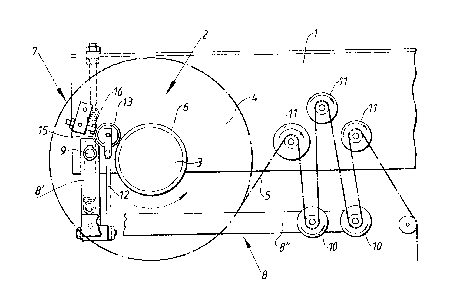
Fig 1 shows the unwinding arrangement in accordance with
the invention from the side, with certain parts, for the sake
vf clarity, being indicated only by dash-dotted contour
lines.
Fig.2 is a rear view of the arrangement in accordance
with Figure 1.
Figs. 3, 4,and 5 correspond to Figure 1 but show the
arrangement in different positions which it can assume during
operation.
The preferred embodiment o~ the unwinding arrangem~nt in
accordance with the invention which is ~hown in Figure 1 is
~pecially designed for use in connection with a packing
machine of the type which is described in Swedish patent
application no. 8202302-9 published October 14, 1983. The
arrangement comprises a stand 1 which is fixed at an
appropriate place on the packing machine. The stand 1 is
provided with a roll stand 2 which comprises a shaft 3
projecting laterally from the stand 1 upon which is placed
tha material xoll 4 of striplike material web 5. The shaft 3
also has a brake drum 6 with an external cylindrical surface
which preferably is located between the material roll 4 and
the stand 1. The material roll 4 is applied to the shaft 3
in a rigid manner by means not shown on the drawing, whereas
the shaft is supported so that it can freely rotate in the
stand 1.
The stand 1 also carries a brake arrangement 7 ~or the
: material wPb 5. The brake arrangement 7 comprises a
~anouvering arm 8 which is suspended pivotably on a point of
support 9 which is constituted of a ~haft projecting at right
angles from the stand 1. The point of support g for the
3-
~ ., " ' : : ~
,, ~, , ~ : ,
:, . . .
132~
manouvering arm 8 is located at some distance from the shaft
3 and substantially on a level with the ~ame. From the point
of support 9 the manouvering arm extends downwards with a
substantially vertical primary arm 8', to the lower end of
which is connected a secondary arm 8". The E;econdary arm 8"
of the manouvering arm 8 extends substantial].y horizontally
from the primary arm 8' and carries at its free end one or
more guide pulleys 10 for the material web 5. Above the
guide pulleys 10 there are a number of further guide pulleys
~0 11 which are supported so that they can freely rotate~on stub
shafts
-3a-
. ~. ~.. .
~, ,0 1 ,
,
. .:
:
~3223~9
pro~ecting laterally from the stand 1. The material web travels
from the roll 4 alternately over the gulde pulleys 10 and 11 and
further to the packing machine, whlch will be explained in more
detail ln the following~
The substantially horizontal secondary arm 8" of the
manoeuvring arm 3 has on its end joined to the! prlmary arm 8' one
or more substantially vertical spiral springs 12, which at their
upper end carry a brake appllance 13 in form of a roller supported
so that it is freely rotatable, the wor~ing surface of which ls
made of a flexible materlal and preferably consists of a number of
0-rings 14 arranged side by side. The splral spring 12 thus
extends largely parallel along the primary arm 8' of the
manoeuvrlng arm 8 and between the polnt of support 9 and the shaft
3 of the brake drum. The splral spring 12 here is of such a
len~th that the brake appliance 13 wlll be located somewhat above
the shaft 3 of the brake drum, and the brake appliance 13 and the
point o~ attachment of the spring 12 ln the manoeuvring ar~ 8 thus
will be located on opposlte side~ of an imaginary line which
connects the point of support 9 of the manoeuvring ar~ 8 wlth the
shaft of rotation 3 of the brake drum 6~ At the opposite side of
the bra~e device 13 in relation to the brake drum 6 a bac~ing
surface 15 is provided which is located on the prlmary ~rm 8' of
the manoeu~ring arm 8 and, more particularly, at the upper end of
the said arm component 8'. When the bra~e appliance 13 ls in its
lnactive position, which ls illustrated ln Flgure l,the distance
between the brake appliance and the s~rface of the brake drum 6
and the distance betwee~ the brake appliance 13 and the bac~lng
surface 15 are substantlally equally large, but the re~pectlve
dlstance varies as a functlon of the state o~ operatlon o~ ths
~rrangement, whlch wlll be expl~ined ln ~ore detail in the
following.
In adltion to the camponents ~entloned up to now the
arrangement in accordance with the lnvention also comprlses a
stopplng devlce 16 in the form of a ~nee pro~ectlng from the stand
1 with an adjustable stop screw, a~alnst whlch the bra~e appliance
13 can re~t. At tha opposite or rear side of the stand 1 the
arrangement also may be provided with a tenslon spring 17 ~hlch
., . .. , . ~ .
13 2 2 3 3 9
e~tends ~rom a point of attach~ent on tbe upper part of the stand
1 to the manoeuvring arm 8 where the lower end of the spring 17 is
connected to an attach~ent 19 projecting from the lower end of the
prlmary ar~ 8 .
Yhen the unwindln~ arrangement in accordance with the
~nvention is used e~g fDr providing packing maclline of ~nown type
with a longitudlnally ~ointed strip the arrangement is connected to
the packing machine ln such a manner that the longitudinally
~ointed strip or material web 5 can be unwoun d directly fro~ the
roll stand 2 via the guide pulleys 11 and 10. The unwlnding
generally takes place at considerably varying sReed, and the
materisl web 5 will be subjected in the process to greater ar
lesser tractlve stresses, that is to say it will be stretched or
slackened to a greater or lesser degree, which via the gulde
pulleys 10 aff0cts the position of the manoeuvring ar~ a.
~ hen thP material web 5 is unwound at substaatially
contlnuous speed, the material roll 4 will adapt to this and rotate
at unlform speed with low unwinding resistance. The welght and
lever length of the manoeuYring arm 8 are adapted 50 that the
material web 5 when it travels alternately over the guide pulleys
and 11 is capable of ~aintalning the manoeuvring arm 8
substantially horizontally, whlch means that the brake appliance 13
ls in a free position at a distance from the e~ternal surface of
the brake dru~ 6 as well as from the backlng surface 15 on the
prim~ry arm 8' of the manoeuvring arm 8. The brake appliance 13
here has no braking function, and the brake drum 6 with the
materlal roll 4 placed on the sha~t 3 can rotate freely at the rate
of the material web 5 belng rolled off the roll.
When the speed of unwlnding of the material web ls sllghtly
reduced, the material web 4, DWin~ to its i~ertia, will rotate a
little too fast so that a certain excess of the ~aterial ~eb 5 is
~ound off, ~hich me~ns that the ~ab slackens o that the ~anoevr-
l~g ar~ by its weight is pivoted downwa~ds ~clockwise) around its
point of support ~, a~d the vertical distance between the guide
pulleys 10 and the guide pulleys 11 i~creases. ~s is shown in
~igure 3 this implies that the spiral spr1ng 12 pivots the
,::
:, . ; , ~ . : "
~3223~9
--6--
brake appliance 13 so that it ~akes contact against the external
surface of the brake drum 6,whereby the brake appli&nce commences
to rotate whilst at the sa~e time deforming the O-rings 14, whlch
means that a light roll reslstance is obtained so that the shaft 3
is braked and the rate of rotation af the material roll is reduced.
The size of the roll resistaace is a function of the web tension,
and when the ~eb tension '5 reduced further, the spiral spring 12
will pr0ss the b~ake appliance 13 with greater force agai~st the
bra~e dru~ 6 so that the deformation of the O-rings 14, ~nd
consequently the roll resistance, incr2ase.
Vhen the p~cking machine is halted, or the consumption of
material ~eb 5 for so~e other reason suddenly ceases or is greatly
reduced, the manoeuvring arm 8 ~ill rapldly pivot further clockwise
to the position shown in Pigure 4, where the brake appliance 13 is
pulled downwards by the spiral spring 12 between the bra~e drum 6
and the upper ead of the prlmary arm ~ , so that it makes contact
not only against the external surface of the brake drum 6 but also
against the backiDg surface 15 on the manoeuvring arm 8~ The
rotation of the brake appliauce 13 will be braked further
2~ thereby,so that a strong brake effect is obtained on the bra~e drum
6~ Since the distance between the nearest parts of the brake dru~ 6
and the backing surface 15 is s~aller than than the dia~eter uf
the brake appliance 13, it is possible through appropri~te sloplng
and shaping of the bac~ing surface 15 ia pr~ctice for the brake
appliance 13 to be wedged up completely bet~een the backing
~urface 15 and the exter~al ~urf~ce of the brake drum 6,thus
bringing ~b~ut a locking of the brake drum, so that the material
roll altogether cannot rotate~ This is promoted further by the fact
th~t the material roll 4 nor~ally rotates anticlockwlse and thus on
contact with th~ brake applla w e 13 endeavours to ~ove the s~e
dowawards towards the wedged up pos$tion. I~ this way ~ny
unrolling of superfluous ~aterial web and damages to the m~terlal
web 5 in tha event o-f sudden stoppa~e of the ~achine are
effectively prevented.
When the machine is started again, and material web 5 is
bei~g con~umed, the tractive tension ln the ~aterial web will
lncrease until the gulda pulleys lU are lifted upwards and the
,:
': ' `,`'' :`
` . , : : : :. ` : .
~2~3~9
-?-
manoeuvring arm B swings anticlockwise again, ~hereby the brakeappllance 13 is lifted from its engaga~ent with the backing
surface and reverts to the nor~al operating position, which varies
between light contact against the bra~e drum 6 ~Figure 3) and the
free po~ition shown in Figure 1.
If a sudden increase in the speed ~f the ~aterlal ~eb 5
w curs this means that the web tension lifts t;he guide pulleys 10
to an upper position shown in Fi~ure 5. When this happens the
brake appllance 13 co~es into contact with the stopping device 18
which via the splral spring 12 successively increases the
resistance of the manoeu~ring arm 8 against furthr anticlockwise
plvoting, so that the pivoting of the manoauvrin~ arm 8 ls braked
gently before the arm attains lts mechanlcal stop position, as a
result of which ~erks or uncontrolled tractive stresses in the
material web are avoided. When the speed of rotatlon of the
material roll 4 increases, the web tenslon will be s~ccessively
reduced, whereby the manoeuvrlng ar~ 8 pivots aga~n clockwl~e to
the normal operatlng positlon.
~hen the arrangement in accordance with ths invention is used
in connection with specially thln and delicate types of ~aterial
webs, or when relatively large and heavy material rolls 4 are used,
the arrangement can be made more effective and quicker to react to
sudden reductions in the web tension , with the help of the teasion
sprin~ 17 which endeavours to act upon the manoevrlng arm ~akin~it
move clw kwise from the central position. The tension spring 17 is
clamped so between the tenslon arrangement la and the attachment
lG? that under normal op~rating condltions ~Fl~.l, Fig.2) it is
substantially straight in front of the point of support 9 of the
arm. When in the event of a sudden reduction in the web tension
the manoeuvring ar~ 8 is pivoted clockwise, the centre of the
spring 17 ~ill be shifted to the left of the point of support 9 and
increase the pivoti~g ~ovement of the arm 8 ln the dlrec~ion
~ towards the braking or locking posltio~ ~Fig.4?. Large rolls too
; are braked effectl~ely iD this ~anaer, so that any stresses upon
the web can be further reduced.
" - - . ~ .. . ...
: .
. : :