Language selection

Search

Patent 1322379 Summary

Third-party information liability

Some of the information on this Web page has been provided by external sources. The Government of Canada is not responsible for the accuracy, reliability or currency of the information supplied by external sources. Users wishing to rely upon this information should consult directly with the source of the information. Content provided by external sources is not subject to official languages, privacy and accessibility requirements.

Claims and Abstract availability

Any discrepancies in the text and image of the Claims and Abstract are due to differing posting times. Text of the Claims and Abstract are posted:

  • At the time the application is open to public inspection;
  • At the time of issue of the patent (grant).
(12) Patent: (11) CA 1322379
(21) Application Number: 1322379
(54) English Title: HIGH PRESSURE ROD SEALING UNIT FOR FLUID PRESSURE GAUGES
(54) French Title: JOINT DE TIGE HAUTE PRESSION POUR MANOMETRE
Status: Expired and beyond the Period of Reversal
Bibliographic Data
(51) International Patent Classification (IPC):
  • F16J 15/02 (2006.01)
  • F16L 55/07 (2006.01)
(72) Inventors :
  • TRAN, DAN V. (Canada)
  • CHUN, AMBROSE S. K. (Canada)
(73) Owners :
  • DAN V. TRAN
  • AMBROSE S. K. CHUN
(71) Applicants :
  • DAN V. TRAN (Canada)
  • AMBROSE S. K. CHUN (Canada)
(74) Agent:
(74) Associate agent:
(45) Issued: 1993-09-21
(22) Filed Date: 1988-07-18
Availability of licence: Yes
Dedicated to the Public: N/A
(25) Language of filing: English

Patent Cooperation Treaty (PCT): No

(30) Application Priority Data: None

Abstracts

English Abstract


HIGH PRESSURE ROD SEALING UNIT FOR
FLUID PRESSURE GAUGES
-DAN VINH TRAN AND AMBROSE SHIU KI CHUN-
ABSTRACT
It is a common problem to devices which are used for segregating
the working fluids, such for example as the drilling mud fluid using in
drilling rig, from the pressure gauges, that the highly polished
cylindrical surfaces for piston sealing are damaged by the solids which
are carried by the working fluid. In this invention, a rod sealing
mechanism is used to eliminate the above problem. In addition, the
spare part which has to be replaced, if necessary, is far more
economical, that is, to replace the rod itself instead of the
internally-polished cylinder.


Claims

Note: Claims are shown in the official language in which they were submitted.

CLAIMS
APPLICATION NO. 572,277
HIGH PRESSURE ROD SEALING UNIT
FOR FLUID PRESSURE GAUGES
BY
DAN VINH TRAN & AMBROSE SHIU-KI CHUN
1. In combination, a pressure rod sealing unit comprising:
an upper body;
a first threaded means inside the lower portion of the
upper body;
first groove means located at the top portion of the first
threaded means;
a lower body with a spherical surface lower portion;
a second threaded means outside the top portion of the
lower body;
second and third groove means located at the inside top
portion of the lower body;
first, second and third sealing means installed in the
first, second and third groove means respectively for
sealing a rod means;
whereby, the upper body and the lower body are connected by
the first and second threaded means, and the rod means is

moving inside the upper and the lower body through the
second and the third sealing means for providing pressure.
2. The pressure rod sealing unit according to claim 1, wherein
the spherical surface of the lower body is connected to a
union sub by means of a wing nut.
3. The pressure rod sealing unit according to claim 2, wherein
the union sub comprises a recessed groove at the upper
portion of the union sub.
4. The pressure rod sealing unit according to claim 3, wherein
a fourth sealing means is disposed between the spherical
surface and the recessed groove of the union sub.
5. The pressure rod sealing unit according to claim 4, wherein
said first, second and the third sealing means are o-rings.
6. The pressure rod sealing unit according to claim 4, wherein
said first, second and the third sealing means are rubber
seals.
69

Description

Note: Descriptions are shown in the official language in which they were submitted.


~22~9
SPE CIEIC AqlO N
This invention relates to the utilization of rod se~ing in the
hydraulically transmitting mechan~sm for f~id pressure measurement by
pressure gauges.
In var~ous industries, it is deqira~Le to mea~ure pressure with a
device which could segregate the working flllid from the contact of the
pressure gauges. Th~s is due to the fact that, ~n many cases, the
working f~i~s carry a large propQrtion c~ suspended scili~ls which
easily contaminate the ~nternal parts of the p~e gauges and that
results in malfunction or inaccuracy of the gauges. Currently, there
are three types c~f these devices, namely, diaphragm type, metal disc
type and piston type. The former two have similar characte~istic
except the use ~ material, that is, the diaphragm type utilizes a
rubber diaphragm while the metal disc a thin EI~d}ile me~iL disc. The
pre~ure is detected by one side of the stationary diaphragm or metal
d~sc and is transmitted to the cther side which con~dsts of usually
clean hydraulic fluid~ However, the disadvantage af these types i5
that they are oliLy use~l at low pr~re range. The d~aphragm and
metal disc usually fail under the high stress creat~d by high pressure.
The pist~n type was desLgned to s~Lve the above problem under high
pre~;ure ap~ ation. ~t usually cor~ists cJE a pdst~n with seals which
travbl inside a p~lished cy~inder. The pr~ure oE the working ~id
..~
~ 2 --

~322~7~
acts on one ~ide of the p~ston and ~s transmitted to the other ~ide by
moving the paston in either direction. However, the disadvantage of
this type of device ~ that -the s(ilids m the working f~l~ids are
usually car~ed by the seals oE the piston and ~hus damaqe the internal
highly p~ilished cylinder during the actuation, which render the
structure moperative. Once the palished cylinder ~s damaged, the
com~lete dev~ce becomes usel~ss for the fact that it cannot be
repaired.
We have -found that the above problem in high pressure application
can be sc~ved by u~}ing a rod sealing mechanism. Because the seals are
not mova~e, the s~lids are hardly carried by the actuating p~ilished
rod beyond the sealing area of the cylinder. This invention ena~s
the device to be more r~liable, durable and economic~ ~:o re~ace spare
parts. The oriLy pc~iLe damage occurs on the rod, which is compara~y
inexpensive to r,o~ace than the cylinder in the cc nventional devices.
The invention is ill~strated in the accompanying drawing in which:
Fi~ure 1 is a uiew in elevation showing the app]ication o~ this
invention to a measurement of press~re af a flow ]ine~
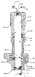
Figure 2 is the sectional view ~f the entire high pr~sure r~d sealing
unit with which t~s invention is partic~y concerned.
:
. . .
,
.. , , ~ .,.

11 322~37~
To measure the press~e o:E a ilow ]ine 10, it ~s normally
connected with a T-Eitting 11 with which a pressure gauge 25 is
connected by high pressure hose 24. Because oE the so~i~s in the fll~id
may damage the pressure gauge 2S~ a device is interpo~d between the
T-Eitting 11 and pressure gauge 25 to segregate the fluids. The
application oE our invention in such device is i~l~strated by the r~d
seaLing mechanism.
A threaded member 12 is connected to ~he top of the 'r~itting 11
at the end and to an union sub 16 at the other end 26. The union sub
16 is threaded externally, with a rubber seal 21 pLaced in a reces~ed
groove 32. When the w~ion sub 16 is tightened by a wing nut 13, the
rubber seaL 21 is squeezed by the end Eace oE the lower body 14 oE the
high press~lre rod se,~ing unit, thus creating a sealing surfaces Eor
high pressure application. In addition, the spherical sl~rEace 29 oE
the lower body 14 and the bevel 30 af the union sub 16 creates a
metad~metaL seaL such that should the rubber seal 21 Eail, the high
press~re is held by such metal~metal seal. The lower body 14 is a
body with internal cylindrical bore. The bottom end clE it has a lip 28
which retains ~he .rod 17 from coming out. The seals 19 and 20 are
instalLed in the grooves on the lower body 14. The highLy pc~ished rod
17 is instaJled from the top so that the seals 19, 20 and the rod 17
create the sealing mechanism. Any fluid w;ll be segregat~d from the
top to the bottom o seals 19 and 20. The upper body 15 with a seal 18
inst~led in the groove is screwed tight on the threaded portion of the
-- 4 --
, '.. ~ , : ' , : '

~3223~
bottom body 14. At the top wall of the upper body 14, there is a
threaded port 31. A T~ittin~ 22 is threaded into the threaded ~Lement
of the upper body 14. A check valve 23 ~s threaded to one outlet of
the T-fitting 22 and a high pressure hose 24 is connected to the other
outlet c~ the T~ tting 22. The other end of the hose 24 is connected
to the high pressure gauge 25. A desirable incompres~i~e ~id fiUs
the hose 24, the T~itting 22 and the space 27 of the upper body lS.
The check valve 23 enables the release of any gaseous components within
the said vciLume. As the incompressible fluid is es~ished, the
sealing rod 17 will be forced downward ur~til it reaches the ~i~ 28 of
the lower body 14. At this stage, the rod sealing unit ~s set for
operation.
As the p.ressure is forced through the i~Low line 10, it wi~l rise
through the threaded member 12, the union sub 16 and to the bottom end
c~E the sealing rod 17. At such a time, the pressure will force the
sealing rod 17 upward and ~n turn force the incompre~ible f~id from
space 27, through the threaded port 31 to the hose 24. This f~id will
then be forced to the pr~isure f~d res~l-s~ve elements of the gauge
25 and thus indicating the pressure of the flow line 10.
:

Representative Drawing
A single figure which represents the drawing illustrating the invention.
Administrative Status

2024-08-01:As part of the Next Generation Patents (NGP) transition, the Canadian Patents Database (CPD) now contains a more detailed Event History, which replicates the Event Log of our new back-office solution.

Please note that "Inactive:" events refers to events no longer in use in our new back-office solution.

For a clearer understanding of the status of the application/patent presented on this page, the site Disclaimer , as well as the definitions for Patent , Event History , Maintenance Fee  and Payment History  should be consulted.

Event History

Description Date
Inactive: IPC from MCD 2006-03-11
Inactive: Adhoc Request Documented 1996-09-21
Time Limit for Reversal Expired 1996-03-23
Letter Sent 1995-09-21
Grant by Issuance 1993-09-21

Abandonment History

There is no abandonment history.

Owners on Record

Note: Records showing the ownership history in alphabetical order.

Current Owners on Record
DAN V. TRAN
AMBROSE S. K. CHUN
Past Owners on Record
None
Past Owners that do not appear in the "Owners on Record" listing will appear in other documentation within the application.
Documents

To view selected files, please enter reCAPTCHA code :


To view images, click a link in the Document Description column (Temporarily unavailable). To download the documents, select one or more checkboxes in the first column and then click the "Download Selected in PDF format (Zip Archive)" or the "Download Selected as Single PDF" button.

List of published and non-published patent-specific documents on the CPD .

If you have any difficulty accessing content, you can call the Client Service Centre at 1-866-997-1936 or send them an e-mail at CIPO Client Service Centre.

({010=All Documents, 020=As Filed, 030=As Open to Public Inspection, 040=At Issuance, 050=Examination, 060=Incoming Correspondence, 070=Miscellaneous, 080=Outgoing Correspondence, 090=Payment})


Document
Description 
Date
(yyyy-mm-dd) 
Number of pages   Size of Image (KB) 
Abstract 1994-03-07 1 22
Claims 1994-03-07 2 53
Drawings 1994-03-07 1 48
Descriptions 1994-03-07 4 150
Representative drawing 2001-08-01 1 13
PCT Correspondence 1991-07-07 1 26
PCT Correspondence 1993-06-13 1 27
Prosecution correspondence 1993-03-30 1 21
Prosecution correspondence 1993-02-14 4 83
Prosecution correspondence 1991-09-10 4 89
PCT Correspondence 1991-10-07 1 31
Examiner Requisition 1992-12-16 2 102