Note: Descriptions are shown in the official language in which they were submitted.
~32~
The present invention relates to an apparatus for
securely fastening a boot to a driving shaft wherein the boot is
fitted over each of both ends of a vehicular-use driving shaft in
such a manner as to cover an open end of a ~oint such as a
constant velocity joint attached to each end of the shaft, said
boot being wound tightly therearound with a band and thus
fastened securely in place, and to a position alignment device
for a driving shaft for use therein. The present invention also
provides a posltion alignment device for driving said apparatus.
Japanese Examined Patent Application No. Tokkosho No.
58-34710 and the Japanese Unexamined Utility Model Registration
Application Publication No. Jikkaisho No. 58-14660 disclose a
band winding device for winding a band around a boot and thus
fastening the boot securely in place. Generally, for fitting a
boot over the driving shaft~ the diametrically larger end thereof
has to be securely fastened to the constant velocity ~oint
attached to the shaft and the diametrically smaller end thereof
to the shaft body. Conventionally, this is done in such a manner
that a worker manually adjusts position of the driving shaft set
in the band winding device and then the diametrically larger and
smaller ends of each of the boots fitted over each of both ends
of the shaft are securely fastened in place successively.
When the operation to fasten the boots securely in
place is performed while adjusting position of the driving shaft
as described in the foregoing, there naturally arises the problem
of a poor work efficiency. To improve the work efficiency for a
higher productivlty, it is desired that there is installed a
working line having a plurality of working stations, each of the
working stations is provided with a band winding device for
winding a band around each of predetermined end portions of the
boot and the driving shaft is conveyed successively to each of
those working stations, so that the boot-fastening operation can
be carried out in a flow process.
- 1 - 7
~2~
It should be noted that at least one of the joints
attached to both ends of the driving shaft is slidable in the
axial direction with respect to the shaft body and the position
of the diametrically larger end of the boot fitted over the joint
changes with a sliding movement of the ~oint, or the boot is
sometimes not fitted accurately over the shaft body and the joint
due to inaccurate positioning thereof. Therefore, how the ~oint
and the boot can be positloned correctly for this operation is a
problem that has to be solved for automation of said fastening
operation.
The present invention provides a boot-fastening
operation solving said problem and in addition a position
alignment device for a driving ~haft for use in said boot-
fastening operatlon.
~ ccording to the present invention there is provided anapparatus for securely fastening a boot to a driving shaft in
which a boot is fitted over each of both ends of a driving shaft
so as to cover an open end of a ~oint attached to each end of the
shaft, and a band is wound around each of both ends of the boot
by means of a ~and winding device so as to fasten both ends of
-the boot securely to the shaft body and the ~oint respectively,
including a working line along which the driving shaft is
conveyed by a conveying ~ig while held thereon, said conveying
~ig having clampers for clamping a shank portion of each of the
joints and the shaft body; the working line having a plurality of
working stations, each of the working stations having a band
wlnding device for winding a band around each of predetermined
end portions of the boot and a positioning device for positioning
the conveying jig; a loader device for setting the driving shaft
on the conve~ing jig remaining in a charging station located at a
starting end o~ the working line; and a position alignment device
for positionally aligning the driving shaft so as to have each of
the ~oints and each of the boots positioned respectively at the
predetermined positions with respect thereto, so that the driving
~ ~ 2 ~
shaft positionally so aligned by the position alignment device
can be set on the conveying jig in said aligned state through the
loader device.
S Thus the present invention provldes an apparatus for
securely fastening a boot to a driving shaft in which a boot is
fitted over each of both ends of a vehicular-use driving shaft in
such a manner as to cover an open end of a ~oint attached to each
end of the shaft, and a band is wound around each of both ends of
the boot by means of a band wlnding device so as to fasten both
ends of the boot securely to the shaft body and the ~oint
respectively, said apparatus including a working line along which
the driving shaft is conveyed by the conveying jig while held
thereon, said conveying ~ig having clampers for clamping the
shank portion of each of the ~oints and the shaft body, the
working line having a plurality of working stations, each of the
working stations having a band winding device for winding a band
around each of the predetermined end portions of the boot and a
positioning device for positioning the conveying ~igt a loader
2~ device for setting the driving shaft on the conveying ~ig
remaining in the charging station located at the staring end of
the working line; and a position alignment devlce for position
alignment thereof so as to have each of the ~oints and each of
the boots positioned respectively at the predetermined positions
wlth respect thereto, so that the driving shaft positionally so
aligned by the position alignment device can be set on the
conveying ~ig in said aligned state through the loader device.
In this case, it is preferable that the conveying ~ig
is provided wlth a vertically movabl~ ~ig frame, said ~ig frame
being provided with the afore-mentioned clampers, and the
foregoing positioning device is provided with a lifter for moving
the ~ig frame upward and downward.
It is also preferable that the present invention
provides a position alignment dev1ce including on a machine frame
~ 32~
a first unit for positioning the ~oint and the boot on one end
portion of the driving shaft and a second unit for positioning
the joint and the boot on the other end portion thereof, each of
both units comprising a stopper for receiving and stopping an
axially outer end surface of each of the ~oints at the
predetermlned position, a first clamper for clamping the shank
portion of each of the ~oints and a second clamper for clamping
each of the boots, said first clamper being movable toward and
away from the stopper and said second clamper being movable
toward and away from the first clamper, both moving in the axial
direction of the driving shaft. It is further preferable that
the unit is provided with a boot stopper for receiving and
stopping the end surface of the diametrically larger end of the
boot fitted over the joint.
The operation of the position alignment device will
further be explained.
For carrying out the position alignment operation, the
shank portion of each of the joints is clamped by the first
clamper of each of the units and then said each first clamper is
moved outward in the axial direction. Accordlng to this
operation, the axially outer end surface of each of the ~oints
~ comes to abut against the stopper of each of the units so as to
position each o* the ~oints at the predetermined position
respectively. Next, each of the boots is clamped by the second
clamper of each of the units and then said each second clamper is
moved outwardly in the axial direction. According to this
operation, said each boot is pushed and moved toward each of the
~oints and then the stepped portlon on the inner periphery of the
diametrically larger end portion of each of the boo$s comes to
abut against the open end of each of the ~oints so as to position
each of the boots at the predetermined position with respect to
each of the ~oints positioned earlier and now serving as the
reference. This ellminates possible defective fitting of said
each boot over each of the ~oints and the shaft body that could
-- 4 --
.
;'','.'' ' ' '' "
~3~2~
arise from inaccurat~ positioning of each boot.
When i-t is feared that the stepped portion of the boot
may be moved too far along the outer periphery of the open end
portion of the ~oint, there is provided according to the present
invention a boot stopper adapted to receive and stop the end
surface of the diametrically larger end portion of the boot so as
to have the boot positioned at the predetermined position.
According to the present invention the driving shaft
positionally aligned is set on the conveying jig remaining in the
charging station through the loader device while being kept in
said aligned position, so that the positioned accuracy of each of
the ~ OilltS and boots with respect to the conveying jig is
secured. In this case, the conveying ~ig holds the driving shaft
in place thereon by clamping it at the shaft body and the shank
portion of each of the ~oints by means of its clampers, so that
the shaft body and the joints are kept together thus not causing
the diametrically smaller and larger end portions of the boot to
become positionally misaligned after set on the conveying ~ig.
Thus, simply by positioning the conveying ~ig by means of the
positioning device at each working station~ each o~ the
predetermined end portions of the boot is accurately aligned in
position with the corresponding band winding device disposed at
each of the working stations and the diametrically smaller and
larger end portions of each of the boots are wound around tightly
by a band and fastened securely in place successively at a
plurality of the working statiQns.
It is possible to arrange it such that the conveying
jig may be movable upwardly and downwardly at each of the working
stations so as to move the driving shaft upwardly and downwardly
for connection with and disconnection from each of the band
w~nding devlces~ Whereas such an arrangement dses inevitably
make the structure of a conveying means for the conv0ying ~ig
complex, the present invention preferably provides the boot-
-- 5 --
~322~1
fastening apparatus wherein the driving shaft can be movedupwardly and downwardly through the jig frame of the conveying
jig by means of a lifter provided on the positioning device and
the main body of the conveying jig is only required to move
rectilinearly along the working line. This leads to a
comparatively simplified structure of the conveying means.
The present invention will be further illustrated by
way of the accompanying drawings in which:-
Fig. 1 ls a top plan view of an embodiment of thepresent invention;
Fig. 2 is a front view thereof as seen from the II-II
line if Fig. l;
Fig. 3 is a top plan vlew of a conveying ~ig;
Fig. 4 is a sectional front view taken along the IV-IV
line in Fig. 3;
Fig. 5 is a sectional view taken along the V-V line in
Fig. 4;
Fig. 6 is a sectional view taken along the VI-VI line
in Fig. 4;
Fig. 7 is an enlarged side view of a relocation device
as seen from the VII-VII line in Fig. l;
Fig. 8 is a top plan view of a position alignment
device;
Fig. 9 is a front view thereof;
~ig~ 10 is a left side view of that shown in Fig 8;
-- 6
~322~
Figs. lla and llb are each an explanatory diagram
illustrating operation of a band winding device;
Fig. 12 is a fro.nt view of a positioning device
provided at a working station;
Fig. 13 is a left side view of that shown in Fig. 12;
Fig. 14 is a sectional top plan view taken along the
XIV-XIV llne in Fig. 12; and
Fig. 15 is a longitudinal sectional view of a driving
shaft.
As shown in Fig. 15, the illustrated example is one in
which a boot Cl is fitt~d over the first ~oint Bl comprising a
tripod type constant velocity joint attached to one end of the
driving shaft A and another boot CZ is fitted over the second
~oint B2 comprising a bell type constant velocity ~oint attached
to the other end of the driving shaft A, wherein the
diametrically larger end of each boot is fastened securely to the
joint Bl or B2, the diametrically smaller end thereof is fastened
to the shaft body Al and in addition a damper weight ~ is fitted
onto the shaft body A1, all fastened by a steel band E wound
tightly therearound.
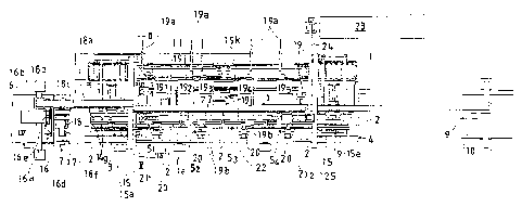
Referring to Figs. 1 and 2, reference 1 denotes a
working line along which a driving shaft A held on a conveying
~ig 2 is convsyed. Between a charging station 3 at the starting
end of the working line l and a discharglng station 4 at the
~ ~ final end of the working line 1 are provided a first to a fourth
: working stations 51~ 52~ $3 and 54. The driving shaft ~ being
brought over by a conveyor 6 from an assembling device (not
shown) i5 transferred by a relocation device 7 onto the conveylng
~ig 2 remaining in the charging station 3. Using a transfer
device 8, said conveying ~ ig 2 is then conveyed ltc each of the
~3~2~
working stations 51~ 52~ 53, 54 successively in that order.
Fastening operation to fasten securely in place the diametrically
larger end of the boot C2 for the second joint B2 is performed at
the first working station 51~ and fastening operations to fasten
securely in place the dlame-trically smaller end of each of the
boot C2 for the second ~oint B2 and the other boot Cl for the
first ~oint Bl are performed at the second working station 52~
fastening operation to fasten securely in place the diametrically
larger end of the boot Cl for the first ~oint Bl is performed at
the third working station 53, and fastening operation to fasten
the damper weight D securely in place is performed at the fourth
worklng station 54. Thereafter, at the discharging station 4, a
discharging device g is operated to remove the driving shaft A
from the conveying ~ig 2 and discharge it onto a discharging
conveyor 10 while the conveying ~ig 2 so emptied of the shaft A
is returned to the charging station 3 through a return conveyor
11 .
As shown in Figs. 3 through 5, the conveying ~ig 2
comprises: a ~ig body 12 which is slidable along guide rails la,
la laid on both sides of the working line l; a ~ig frame 13
e~tending longitudinally and supported on a pair of front and
rear guide rail 13a, 13a fixed to the ~ig body 12 so as to be
movable upwardly and downwardly therealong; and a first clamper
141 for clamping a shank portion of the first joint Bl, a second
clamper 142 for clamping the shaft body Al, and a third clamper
143 for clamping a shank portion of the second joint B2, all of
these clampers being mounted on the jig frame 13. As shown in
Fig. 6, each of the clampers 141, 142 and 143 is so arranged that
a pair of left and right clamp claws 14c, 14C' are laterally
slidably supported through a pair of upper and lower guide bars
14b, 14b on a holder 14a provided on the ~ig frame 13, and a pair
of upper and lower racks 14e, 14e' engaging with a pinion 14d
pivotally supported on the holder 14a are respectively connected
to both the clamp claws 14c, 14c' so as to cause both the clamp
claws 14c, 14CI to move laterally in a mutually synchronized
~ 3 ~
fashion to open and close.
One of the clamp claws 14c is urged by a spring 14f
toward the closing side so as to keep each of the clampers 141,
142 and 143 normally held in the clamped posltion while there is
provided on the holder l~a a push member 14g which pushes the
other clamp claw 14c' toward the opening side. In addition, the
charging station 3 and the discharging station 4 are each
provided with an operating device 15 comprislng a longitudlnally
extending push plate 15a which faces the push member 14g of each
of the clampers 141, 142 and 143 and is arranged so as to be
movable back and forth ln the lateral direction, so that each
push member 14g may be pushed in by the push plate 15a for
operation to unclamp each of the clampers 141, 142 and 143.
Furthermore, in order to be able to handle driving
shafts A of different lengths, the first and the second clampers
141 and 14~ are mounted in such a manner that they may be moved
longitudinally along a guide rail 14h for positional ad~ustment
with respect to the ~ig frame 13.
Reference numeral 12a in the drawings denotes a pair of
positioning blocks fixedly attached to the ~ig body 12, and 13b
represents an operating arm fixedly attached to the ~ig frame 13
for lift operation.
As shown in Figs. 1 and 7, the relocation device 7
comprises a first loader device 16 for receiving the driving
shaft A from a work receiver 6a provided at the final end portion
of the conveyor 6, a positlon alignment devlce 17 disposed
between the conveyor 6 and the charging station 3, and a second
loader device 18 for delivering the driving shaft A to the
conveyi~g ~ig 2. The first loader device 16 is arranged to
comprise a machine frame 16a disposed above the final end portion
of the co~veyor 6, a slide frame 16b mounted on the machine frame
16a so as to be movable back and forth, three clampers 16c for
~ 3 ~
clamping the driving shaft A detachably at the shank portions of
the first and the second joints Bl and B2 and at the shaft body
Al, a clamping head 16d extending lengthwise in the lateral
direction and having said three clampers 16c thereon, said
clamping head 16d being mounted on the slide frame 16b in such a
manner as to be moved upwardly and downwardly by a cylinder 16e.
In the above arrangement, the clamping head 16d is caused to
receive the driving shaft A from the work receiver 6a while the
slide frame 16b is in its retreated state. Then, by mov~ment of
the slide frame 16b, the clamping head 16d is moved forward and
downward to transfer the driving shaft A to the position
alignment device 17. Further, the second loader device 18 is
arranged to comprise a machine frame 18a extending longitudinally
from a location above the position alignment device 17 to a
location above the charging station 3, a slide frame 18b
supported on the machine frame 18a so as to be movable back and
forth, a lift frame 18d mounted on the slide frame 18b through a
cylinder 18c, and a clamping head 18f equipped with three
clampers 18e as is the foregoing clamping head 16d and hung from
the lift frame 18d through a rotary actuator 18g so as to be
turnable. In ~his arrangement, after turning the clamping head
18f to a sidewise-facing posture in which its lengthwise
direction is in line with the lateral direction, the clamping
head 18f is caused to receive the driving shaft A on the position
alignment dPvice 17 and then turned to a longitudinally-facing
posture so as to have the first ~oint Bl of the driving shaft A
positioned in front. In this condition, the clamplng head 18 is
moved to a location right above the charging station 3 and then
moved downward so as to set the driving shaXt A on the conveying
jig 2 being returned to the charging station through the return
conveyor 11. It should be noted here that the clamper 16c or l~e
of each of the loaders 16 and 18 are so mounted a~ to be
ad~ustable in position in order to be able to deal with different
types of the shaft.
The position alignment device 17 is, as shown in Figs.
-- 10 --
8 through lo, arranged to comprise a first unit 17bl for
positioning the first joint Bl, which is sli.dable with respect to
the shaft body Al, and the boot Cl, and a second unit 17b2 for
positioning the second joint B2 and the boot C2, both units being
mounted on a machine frarne 17a. Thus, the diametrlcally smaller
and larger ends of each of the boots Cl and C2 are correctly
fitted over the joints Bl and B2 and the driving shaft body Al
respectively by these units 17bl and 17b2 and at the same time
each of the joints Bl and B2 iS positioned thereby. In this
manner, i-t functions to provide position alignments for the
diametrically smaller and larger ends of the boots Cl and C2.
In order to be able to deal with possible model changes
of the shaft, the foregoing first unit 17bl is arranged to
comprise a base plate 17d mounted on the machine frame 17a in
such a manner as to be advanced and retreated for position
ad~ustment by operation of a control bolt 17c having a handle, a
stopper 17e fixedly mounted on said base plate 17d to receive the
end surface of the first ~oint Bl, a slide table 17g mounted on
20 the base plate 17d so as to be advanced and retreated by a
cylinder 17f, a first clamper 17hl mounted securely on said table
for clamping the shank portion of the first joint Bl, and a
second clamper 17h2 also mounted on the table 17g for clamping
the boot Cl, said second clamper being movable back and forth by
means of a driving source (not shown). Furthermore, the
foregoing second unit 17b2 is arranged to comprlse a stopper 17i
for receiving the end surfaces of the second ~oint B2, said
stopper being fixedly mounted on the machine frame 17a, a slide
table 17k mounted on the machine frame 17a and moved back and
forth by a cylinder 17~, a pair of first clampers 17~ , 17~ 1
fixedly mounted on sald slide table 17k and used for clamping the
shank portion of the joint B2 and the shaft body Al, and a second
clamper 17~ 2 for clamping the boot C2 being mountad on the slide
table 17k in such a manner as to be moved back and forth by a
driving source (not shown). In this arrangement, each of the
driving shafts A krought in by the first loader device 16 is
-- 11 --
~22~
clamped at tne shank portion of each of the ~oints Bl and B2 and
the shaft body ~1 thereof by the first clampers 17hl and 17~ 1 of
both units 17bl and 17b2 and then the slide tables 17g and 17c of
the respective units 17bl and 17b~ are moved outwardly along the
axial l~ne of the driving shaft A so as to have each of the
~oints Bl and B2 properly positioned by bringing the end surfaces
of the -Joints Bl and s2 to abut against the stoppers 17e and 17i
respectively. Next, the boots Cl and C2 are clamped respectively
with the second clampers 17h2 and 1 ~ 2 of the respective units
17bl and 17b2 and then each of the second clampers 17h2, 1 ~ 2 is
moved outwardly along the axial line, so that a stepped portion
Ca on the inner periphery of the diametrically larger end portion
of each of the boots Cl and C2 may hlt the open end of each of
the ~oints Bl and B2 so as to position each of the boots Cl and
C2 with respect thereto.
Since the open end of the second ~oint B2 is somewhat
round-shaped~ the stepped portion Ca of the boot C~ being fitted
over the second ~oint B2 is pushed sometimes too far along the
outer perlpheral portion of said second ~oint B2 as the boot C2
is pushed by push-in force of the second clamper 17~ 2. In order
to avoid such from occurring, an embodiment of the present
inventlon shown in the drawings has a boot stopper 17m provided
on the slide table 17k so as to receive and stop the leading end
-25 surface of the diametrically larger end of the ~oint B2, said
stopper 17m being so designed as to be opened and closed as
desired.
As described~ the drlv1ng shaft a can be pos1tionally
ad~usted so that it may be accurately positioned and set on the
conveying jig 2 through the second loader device 18 so as to have
each of the boots Cl and C2 disposed at the predetermined
positions with respect thereto.
Each of the foregoing working stations 51~ through 54
is provided with a band winding device. Namely, the first
- 12 -
~22~
working station 51 is provided with a first band winding device
191 suitable for band winding on the diametrically larger end
portion of the boot C2 for the second joint B2; the second
working station 52 is provided with two units of the band winding
device including a second band winding device 192 suitable for
the diametrically smaller end of the boot C2 for the second ~oint
B~ and a third band winding device 193 suitable for the
diametrically smaller end of the boot Cl for the flrst ~oint Bl;
the third working station 53 is provided with a fourth band
winding device 194 suitable for the diametrically larger end of
the boot Cl for the first ~oint Bl; and the fourth working
station 54 is provided with a fifth band winding device 195
suitable for the damper weight D. In addition, each of the
working stations 51 through 54 is provided with a positioning
device 20 for posltioning the conveying jig 2 and then lifting up
the driving shaft A to a predetermined position, so that a band E
winding operation is performed by means o~ each band winding
device while the driving shaft A is held lifted up.
Each band winding device is arranged such that, as
shown in Fig. 2, it is provided with a winding head lsb for
supplying a band E being drawn out from a band coil l9a, an arm
l9c pivotally support~d on the winding head l9b is swung upwards
from an escape position below after the driving shaft A has been
lifted up 50 that the portion to be wound therearound with the
band E may be surrounded by a pair o~ left and right guide pieces
lgd, l9d provided on the winding head 19b and another ~uide piece
19~ attached to the arm 19c in such a manner as to leave a
clearance therebetween as shown in Fig. lla. The band E is then
fed in through this clearance to be wound for a littls over one
turn around the outer periphery of the portion to be wound
therearound with the band E, and the band E is then tightened in
place by these guide pieces l9d and l~e while a presser member 9h
provided with a cutting edge l9g and inserted in a guide sleeve
l9f is moved downward for cutting the band E. After cutting the
band E as above, the overlapped portion of both ends of the band
~3~2~
E is lrradiated with laser beams emitted from a laser lrradiation
head 21 which will be discussed later, said laser beams being
applied to the overlapped portion through an irradiation hole
formed in the presser member l9h, thereby welding the band E.
Reference numeral l9i in these figures denotes a back bar mounted
on the winding head l9b so as to be movable back and forth along
the axial line of the shaft A and support the overlapped portion
thereof from inside~
The arrangement of the band winding device is not
particularly different from that disclosed in the Japanese
Unexamined Utility Model Registration Application No. Jikkaisho
58-146630, so that any further detailed description thereof is
omitted.
5
ln this embodiment of the present invention~ the second
through the fifth band winding devices, 192~ to 195, are arranged
to be moved back and forth through the control bolt l9k by each
of the motors 19~ as shown in Fig. 1 so that their positions may
0 be changed according to the type of the shaft ~.
The positioning device 20 is, as shown in Figs. 12
through 14, arranged to compriseo a machine base 20 disposed
outside of the guide rail la on one side of the working line l; a
2~ pair of positioning pins 20c, 20c mounted on the machine base 20a
in such a manner as to be movable back and forth in the lateral
direction by a cylinder 20b, a lifter 20g so mounted as to be
moved upwardly and downwardly by a cylinder 20f along a guide
rail 20e securely attached to a support column 20d erected on the
machine ~rame 20a; and a stopper 20h atkached to the upper end of
the support column 20d. In this arrangement, each of the
positioning pins 20c is advanced inwardly in the lateral
direction to be engaged with each posltloning block 12a securely
mounted on the ~ig body 12 of the conveying ~ig 2, thereby
positioning the conveying ~ig 2. Next, the lifter 20g is moved
upward to push up the ~ig frame 13 of the conveying ~ig 2 through
- 14 -
the operating arm 13b until the arm 13b comes to abut against the
stopper 20h, so that the driving shaft A supported on the ~ig
frame 13 through the clampers 141, 142 and 143 is lifted up to
the predetermined position.
When the shaft dlameter and/or ~oint diameter of a
driving shaft are changed due to change in type thereof, it is
necessary to change the liftup position of the driving shaft A in
accordance with the change. To meet this need, according to an
embodiment of this invention, two stoppers 20h, 20h which are
different in height from eàch other are mounted on a sllder 20i
attached to the upper end of the support column 20d so that the
stoppers 20h, 20h may be selectively moved to and set at their
operating positions matching the position of the lifter 20g.
Furthermore, there are provided on the working line two
laser beam irradiation heads, a fist irradiation head 211 and a
second irradiation head 212, both of which are movable back and
forth. The first laser beam irradiatisn head 211 is moved to a
position at which it is aligned with one of the first and the
second band winding devices 191, 192 and then the second laser
beam lrradiation head 212 is moved to a position at which it is
aligned with one of the third through the fifth band winding
devices, 193, 194, 195, said movement of the first laser beam
irradiation head 211 being made alternately with that of the
second laser beam irradiation head 212, and a laser beam emitted
from a laser beam generator 22 is led alternately into each of
the laser beam irradiation heads 211, 21~ so that the two
irradiation heads 211, 212 can take care of welding the
overlapped portions of the band E wound up by the five band
wlnding devices 191 through 195 according to the above-descrlbed
allotment of the welding work.
Now, the overall operation of this embodiment of the
present invention will be explained.
- 15 -
~2~1
The driving shaft A brought in by the conveyor 6 is sat
on the position alignment device 17 by the first loader device 16
and positionally aligned by the position alignment device 17 so
that each of the ~oints Bl, B2 and each of the boots Cl, C2 may
be positioned respectively at their predetermined positions with
respect to the shaft A. Then, in this condition, the driving
shaft A is set by the second loader device 18 on the conveying
~ig 2 remaining in the charging station 3.
Next, the conveying ~ig 2 on the working line 1 is
moved therealong successively to the working stations and
positloned properly at each of the working stations 51 through 54
by means of the positioning device 20 whil~ the driving shaft ~
is lifted up to its predetermined position through the ~ig frame
13 by means of a lifter 20g provided in each positioning device
20. Next, the band E is wound around each of the predetermined
tight-binding portions by means of each of the band winding
devices 191 through 195. More specifically, the first band
winding device 191 is used to wind the band E around the
diametrically larger end portion of the boot C2 for the drivlng
shaft A remaining in the first working station 51~ the second and
the third band winding devices 192~ 193 are used to wind the band
E around the diametrically smaller end portions of the boots C2
and Cl for the driving shaft A remaining in the second working
station 52~ the fourth band winding device 194 is used to wind
the band E around the diametrically larger end portion of the
boot Cl for the driving shaft A remaining in the third working
station 53, and the fifth band winding device 195 ls used to wind
the band E around the damper weight D fitted over the driving
shaft A remaining in the fourth ~orking station 54.
In this operation, each conveying ~ig 2 keeps on
holding the driving shaft A thereon in such a manner that each of
the ~oints Bl, B2 and the shaft body Al may be held fast by the
clampers 141, 142 144 attached to the ~ig frame 13 so as not to
move ln the axial d~rection of the shaft while the dlametrically
~3~2~
smaller and larger end portions of each of the boots Cl, C2 are
kept positioned respectively at the prede-termined positions with
respect to each conveying jig 2 as in the same condition in which
they are positionally aligned by the position alignment device
17. Thus, at each of the working stations, the diametrically
smaller and larger end portions of each of the boots Cl, C2 are
accurately aligned in position with the corresponding band
winding devices for carrylng out the band windlng operation
without an error.
Next, the band E so wound up by each of the band
winding dèvices 191 through 195 as above is welded by means of
the two laser beam irradiation heads 211, 212. Then, the jig
frame 13 of each conveying jig 2 is moved downward and each
conveying ~ig 2 is conveyed to the next working station to
complete one cycle of operation.
As described according to the present invention the
driving shaft is held on the conveying jig in such a condition
that it is positioned so as to have the diametrically smaller and
larger end portions of each o~ the boots attached to both end
portions thereof accurately fitted over the shaft body and each
of the ~oints and held at the predetermined positions, and the
conveying ~ig is conveyed successively to a plurality of working
stations to wind the band accurately and tiyhtly around the
diametrically smaller and larger end portions of each of the
boots, using the band winding device disposed at each of the
working stations, thereby fastening them securely in place. This
enables the boot-fastening operation to be performed
automatically with a higher work efficiency, which is one of the
advantageous effects brought about by the present invention.
Further, according to a pref~rably embodiment of the
present invention the driving shaft can be moved upwardly and
downwardly at each of the working stations thrcugh the ~ig frame
provided on the conveying ~ig, so that the ~ig body of the
- 17 -
-
~32~
conveying ~ig need not be moved upwardly and downwardly. This
leads to struc$ural simplifications of the conveying means.
According to the present invention a still further
embodiment of the driving shaft can be accurately aligned in
position so that the diametrically smaller and larger end
portions of each of the boots may be fltted accurately over the
shaft body and each of the ~oints and held at their predetermined
positions. Still further, according to another embodiment of the
present invention accuracy in positional alignment of the boots
can be further improved.
- 18 -