Note: Descriptions are shown in the official language in which they were submitted.
~32~
BA~KGROUND OF Tl~ 1NVENTION
, This invention relates to gui~3ance systelos for laser
surgery. More s~ecifically, the present invention relates to a
control system which is able to precisely maintain the proper
, position of a laser beam during surgery. This invention is
~, particularly, but not exclusively useful for controlling a
~ laser surgical device during ocular surgery without
8 immobilizing the eye.
DISCUSSION OF THE PRIOR ART
Il Medical surgical procedures ùsing laser beams to alter
12 tissue in the target area have been practiced for many years
13 with great success. Fortunately, as our know]edge of lasers is
14 increased, there is a concomitant recognition of new ways in
15 which lasers can be effectively employed~ Ophthalmic surgery
16 is one field of use where new uses for laser surgery have been
17 efficaciously applied.
18 A real problem with ophthalmic or ocular surgery, however,
19 is the fact that the eye is so easily moved. Additionally, of
course, the sensitivity of this very delicate organ creates a
21 whole set of unique concerns. Thus, there is a widely
æ recognized need to be extremely precise with any procedure
23~ which alters tissue of the eye. It happens that the more
24 precise the surgical instrument can be in its operation, the
25 more the~e is a desire to bene~it ~rom that pcecision by having
26 ~
.` ~ -1-
., :
~ --:- - . - . - , . :
.. ' ' ' ' ' .
~3~77~
accurate control over the instrument in its rela~ionship with
, the eye.
:~ In the past, various attempts have been made to ~ixedly
hold the eye durin~ ocula~ surgery. An example o~ a device
intended Eor this purpose is ~ound in U.S. Patent No. 4,665,913
6 to L'Esperance Jr. wherein an eye retaining fixture is
_ disclosed. Specifically, a device of this type is suction-
8 fitted onto the eye to establish external means by which the
9 eye can be held. As might be expected, the use of such a
~) device can be very painful for the patient and the efficacy of
such a device can be questioned.
12 Unlike the devices of the prior art which require
immobilization of the eye in order to achieve their precision,
14 the present in~ention achieves the re~uired operative precision
while allowing the eye some degree of movement. Specifically,
16 the present invention recognizes that precise ophthalmic
sur~ical procedures can be accomplished without immobilizing
l8 the eye. This is possible because, unlike the prior art
l9 devices, the present invention further recognizes that an
ophthalmic surgery device can be programmed to track the eye by
21 monitoring references which are marked on the eye in a known
~2 relationship with the visual axis of the eyeO
2:~ In light of the above, it is an objec~ of the present
2~ inventlon to provide an eyetracker which will keep an
ophthalmic surgery~device in a preprogrammed relationship with
26 the visual axis o~ the eye during surgery. Another object o~
-2-
: :
.
r~
the present inventioil is to provide an eyetracker which allows
, the accomplishment o~ ophthalmic surgical procedures without
immobilizing the eye. Still another object o~ the present
invention is to provide a device which is useful for
identifying either the visual axis or the symmetrical axis of
~, the eye. Yet another object of the present invention is to
provide a reference grid on the cornea of the eye which has a
known relationship with the visual axis of the eye and which
~ precisely identifies the areas of the cornea on which surgical
1~ procedures are to be performed. A further object of the
present invention is to provide an eyetracker for use with
1~ ophthalmic laser surgical instruments which is easy to operate,
1:~ relatively easy to manufacture and which is cost effective.
1_ 5UMMARY OF THE INVENTION
16 A preferred embodiment of the novel eyetracker comprises a
1, visual light source on which a patient can fixate to coaxially
18 align the visual axis of the patient's eye with a segment of
19 the axis of the visual light beam. A laser source also
coaxially aims its beam along this axis segment of the visual
light beam. Thus, when the patient's eye is fixated, a
,~, reference alignment is established between the eye's visual
2~ axis and the laser beam since the eye's visual axis and the
~; ~ 2s lasee beam are both coaxially aligned on the same axis
2; segment. While the patient's eye is initially in re~erence
26 alignment, the laser source is activated to mark a grid on the
-3-
', ,`
~ 3 ~ ~ r~
cornea o~ the patient's eye which fi~es a ~nown rel~tionship
. between the grid and the eye's visual axis.
:~ A source of diffused infrared light is ~rovided to
illuminate the grid marked cornea. Reflections therefrom are
optically directed to a sensor where movements o~ the grid out
~, of its reference alignment are detected. At the sensor,
_ variations in the intensity of the reflected infrared light are
used to generate signals which are representative of any grid
(~ movement. These signals are then transmitted by electronic
ln means from the sensor to a comparator. In the comparator, each
ll grid movement signal is compared with a reference signal which
12 is representative of the grid position when in reference
1:~ alignment. An ercor signal, proportional to the difference
between the "grid in reference alignment" signal and the "grid
movement~ signal, is generated and transmitted to a guidance
16 system which steers the laser beam in a manner that reduces the
17 error signal to a null. While! maintaining the error signal at
a null, the laser beam is steered to make contro]led external
19 or internal ablations of the cornea in accordance with a
predetermined computerized program.
21 In addition to the use o diffused infrared light for
monitoring grid movement to establish a closed loop feedback
23 control for the laser guidance system, the source of difused
~ .
24 infrared light may also be used to help identify the eye's axis
~ ~ ~ 2~ of symmetry. For this latter purpose, the sensor i5 focused on
: ~
~26 ~the plane of the iris rather than on the cornea. When focused
,
. . ~ ~ '
. - :
.
~ 3 ~ 6
on the plane of the iris, the sensol- is focused along a
~ plurality of lines to detect the intensit~ o~ the light that is
:~ reflected from the sclera, the iris and the pupil. The sensor
~1 then transmits this information to a computer which uses it to
precisely determine the exact relations1-ip between sclera, iris
6 and pupil. Also, a beam of collimated in~rared light from a
7 laser diode is focused onto the cornea. In alternation with
8 its focus on the iris plane, the sensor is focused on the
9 cornea to scan the cornea and detect specular reflections from
the beam of collimated infrared light. Due t~ the shape of the
cornea, the specular reflection of greatest intensity will come
12 from the apex of the cornea. Since the sensor is preferably a
13 line diode, the apex of the cornea is identified when the most
14 intense specular reflection falls on the center o~ the line
diode. This information is also sent to the comparatcr where
16 information from the iris plane concerning the relationship of
17 the sclera, iris and pupil, and information from the corneal
18 plane concerning the apex of the cornea a~e used together to
19 detecmine the eye's axis of symmetry.
With the information obtained as discussed above, surgical
21 laser operations on the cornea can be accomplished using the
2~ reference alignment without immobilizing the eye~ This is
23 accomplished whether the reference alignment is made directly
24 on the visual ax1s of the eye or on the visual axis as
, empirically determined by its relationship with the eyeis axis
2-, of symmetry.
:.
-5-
13227~? i
l The novel features of this invention, as well as the
.~ invention itself, both as to its structure and its operation,
:~ will be best understood ~rom the accompanying drawings, taken
.~ in conjunction with the accompanying description, in which
similar reference characters refer to similar parts, and in
6 which:
7 BRIEF DESCRIPTION OF THE DRAWINGS
8 Figure 1 is a side elevation view of surgical equipment
. 9 comprising the present invention operatively positioned for
surgery on a patient's eye;
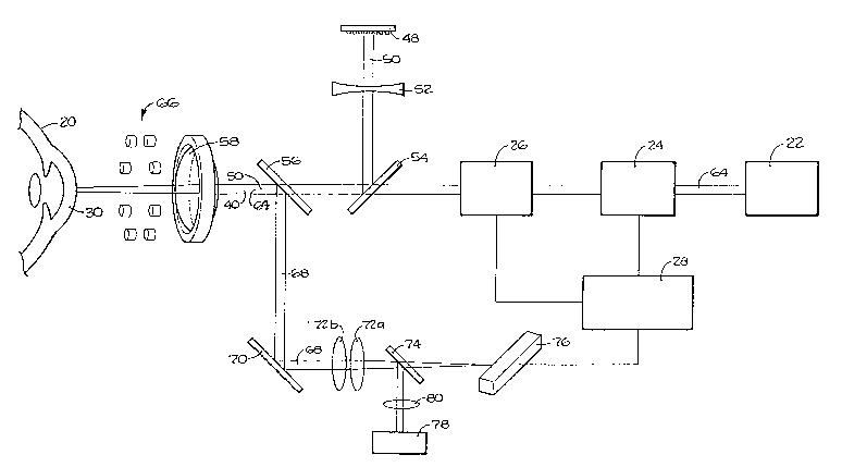
Il Figure 2 is a schematic view of the eyetracker and its
12 associated optical elements shown in relationship with a cross-
13 sectional vie~ of a portion of an eye;
14 Figure 3 is a cross-sectional view of a portion of an eye;
Figure 4 is a front plan view of an eye marked with a
16 grid;
17 Figure 5 is a front plan view of an eye shown with
1~ superposed representative scan lines,
19 Figure 6 is a graph of the intensity of light reflected
from the iris plane of an eye along a preselected scan line;
~1 Figure 7 is a graph of the intensity of light reflected
: " : from the cornea of an eye under prescribed conditions; and
23 Figure~8~ is a functional block diagram of a closed-loop
24 feedback system as lncorporated into the electronic circuitry
2S of the eyetracker.
2fi
.`
~ -6-
~:
13 2 ~
DEscRIp~rIoN OF TIIE PREFERRED EMBODIMENT
. Referring initially to Figure 1, it is to be appreciated
that the eyetracker of the present invention is a component o~
a surgical laser device yenerally designated 10. As shown in
Figure 1, surgical laser device 10 with its componen~
~, eyetracker is operatively positioned for surgical procedure on
_ - patient 12. Although patient 1~ is sho~n sitting in a chair 14
for purposes of ophthalmic or ocular surgery, it is to be
~J understood that patient 12 may be placed in a reclining
n position on an operating table (not shown) without compromising
ll the effectiveness of the present invention.
12 The patient 12, while sitting in chair 14, is placed with
l3 his/her head 16 positioned within a restraint 18 for purposes
l4 of reqtricting movement of his/her head during surgical
IS operations. In accordance with the present invention, the eye
16 ~0 of patient 12 need not be immobili2ed during surgery.
I Instead, the present invention is intended to compensate for
l8 modest movements of eye 20.
It is to be understood that the present invention is
2() preferably intended for use with a laser guidance system of the
21 type disclosed in our co-pendin-3 Cana2ian application fo~ an
inventlon entitled "3-Dimensional Laser Beam Guidance System"
which was fi-led on January 9, 1989, under serial number
24 578,805. The majoc components of this guidance system are
2~5 shown in Figure 2 in cooperation with elements of the present
26 invention and are shown to generally comprise a fine tuner 24,
-7-
3 ~ r~ r~
a focusing element 26 an* a laser source 22 of a type disclosed
, in our co-pendir-g Cana~ian applicat_on entitled "Multiwave-
length Laser Source" which was filed on September 27, 1988,
s7~, s~
under serial number ~ 6~ A comparator (computer) 28. is shown electrically connected to provide programmable input:
~, for fine tuner 24 and locusing element 26 of the guidance
_ ~ system.
Refer~ing for the moment to Figure 3, a brief description
~ of eye 20 and certain of its geometric properties will be
helpful. Specifically, in Figure 3 it will be seen that a
1l cross-section of eye 20 reveals a cornea 30 which is set apart
12 from the iris 32 of eye 20. It will also be appreciated that
l:~ iris 32 establishes pupil 34 of eye ~0 and that a lens 36 is
~4 functionally positioned relative to the iris and behind the
pupil, substantially as shown. A greater detailed description
16 of the hu~an eye 20 need not be provided -for an adequate
l7 description of the functioning of the present invention.
l8 However, some very important concepts with regard to the
l9 alignment of eye 20 are important insofar as the present
invention is concerned.
It is well known that the human eye can be discussed with
regard to two separate axes. First, there is the axis of
23 symmetry 38. Essentially, as the name implies, the axis o~
24 symmetry 38 is that axis about which a rotation of a section of
2~ the eye will generate a three dimensional model of the complete
26 eye. It happens, however, that the visual functioning o the
8-
,~:. ,~
- . '
~322 ~ ~
eye does not occur along the a~is o~ symmetry 38. Instead,
, visual acuity occurs alon~ a visual axis 40. As indicated in
:~ Figure 3, there is a slight off-set 42 between the axis of
1 symmetry 38 and the visual axis 40. Although the magnitude o~
this of~-set will vary slightly from individual to individual,
it can be empirically determined and is generally around five
_ degrees. It is also helpful ~o} an understanding of the
~ present invention to define the corneal plane 44 as that plane
9 which i5 tangential to the cornea 30 at the point where the
axis of symmetry 38 is normal to cornea 30. Also, it is
11 helpful to define the iris plane 46 as that plane which
12 generally passes across the pupil 34 between the diametrical
13 extensions of iris 32.
Referring back to Figure 2, it will be seen that the
1S eyetracker of the present invention includes a source of
visible light 48. Preferably" source 48 is a quadratic array
17 of light emitting diodes which radiate blue-green light. Light
In beam 50, which radiates from visible light source 48, passes
~9 through a negative lens 52 and is reflected by turning mirror
54 toward a selectively re~lective mirror 56. After passing
21 through mirror 56, beam 50 of visible light passes through
objective lens 58 and is incident upon cornea 30 of eye 20.
23 Preferably, and for reasons to be more clearly.apparent after
24 subsequent discussion, selectively reflective mieror 56 is
~: :
transparent for visible light and for all wavelengths used for
~; 26 the cutting laser beam from laser source 22. On the other
_g_
:L3~ lJ ~
hand, selectively reflec~ive mirror 56 should be reflective for
, infrared components of light and, more specifically, mirror 56
sho~ld be reflective of infrared light having wavelengths which
are radiated by diode array 66.
It will be recalled that visual axis 40 is the most
~, important reference insofar as vision is concerned. Therefore,
in ocular surgery, some operative reference to visual axis 40
~3 needs to be established. This is done, in accordance with the
) present invention, by directing visible light from source 48
toward eye 20 to establish a spot of light upon which the
patient 12 can fixate. Accordingly~ if patient 12 fixates on
the beam 50 of light coming from source 48, the visual axis 40
1~ of eye 20 will be coaxially aligned with beam 50. This coaxial
l4 alignment is extremely important insofar as the present
l~ invention is concerned since, as inferenced above, in
16 ophthalmic or ocular surgery it is desirable that corneal
surgical procedures be accomplished with reference to the
18 visual axis 40.
19 With visual axis 40 of eye 20 coaxially aligned along a
~ portion of beam 50 of visible light, a reference grid 60 is
2l marked on the cornea 30 of eye 20. This marking of grid 60 is
,~, accomplished by laser beam 64 which originates at source 22.
23~ Specifically, laser beam 64 is coaxially aligned within device
24 10 along that portion of beam 50 which is directed by turning
mirror 54 toward eye 20. Thus, when patient 12 fixates on beam
26 50, laser beam 64 is coaxially aligned with the visual axis 40
: :` : : :
-10-
,
'
~ 7r~
o eye 12. Tilis caged coaxial alignment between visual axis 40
, a~d lasee beam 64 is referred to herein as the reference
alignment and is used by the eyetracker of the present
invention as a base from which subsequent movement of laser
beam 64 is rnonitored.
~,Optically, device 10 uses movement o~ grid 60 to control
_ movement of laser beam 64. Therefore, grid 60 must be marked
~ when visual axis 40 and laser beam 64 are in reference
<~ alignment. Specifically, as patient 12 fixates on beam 50 from
light source 48, laser source 22 is activated and steered by
proper programmed input to fine tuner 24 in a manner which will
l~ establish a grid or template of small incisions on cornea 30 of
1:~ eye 20. Momentarily referring to Figure 4, a grid generally
14 designated 60, as envisioned by the present invention, is shown
15marked on cornea 30 of eye 20. From Figure 4, it will be
l~, appreciated that a series of slpots 62 are cut into cornea 30 in
17 any manner desired by the operator for subsequent procedures.
l~ ~s shown in Figure 4, groups of spots 62 may be arranged in a
I9 coded fashion. Such codinc~ can be subsequently used at-
2() comparator 28 to furthee identify the orientation of eye 20.
2l Preferably, spots 62 are small incisions created in cornea 30
~' by the cutting laser 64 from laser source 22. Further, it is
23 preferable that spots 62 be approximately ten microns in depth
4 and approximately ten microns in diameterO It has been ~ound,
in accordance with the present invention, that these small
26 ~
.
i., ,.,. ,: . .
~ 3 2 ~ `J
spots when cut in~o cocnea 30, provide a sufficient o~tical
reference for ~urther operation of the eyetracker.
Referring back to Figure 2, it will be seen that a
monitoring system is provided to efLectively track movement of
~ eye 20. For this ~urpose, an annular array of diodes 66 is
6 positioned in device 10 between eye 20 and objective 58 to
7 radiate diffused infrared light onto cornea 30 of eye 20. This
8 light will be re1ected from cornea 30 with information
9 concerning the spots 62 which have been cut into cornea 30 to
establish grid 60. This reflected light passes through
objective ~8 and is incident on selectively reflective mirror
12 56 where it is further reflected along a path 68 toward
l3 galvanometric mirror 70. Although selectively reflective
14 mirror 56 can be established to reflect various wavelengths of
light, this ceflectivity must be compatible with the light
16 emitted from diode array 66. Therefore, preferably, mirror 56
17 is reflective of light having wavelengths approximately 940
l8 nanometers. Such wavelength would be typical for an infrared
19 source such as intended for diode array 66. On the other hand,
it will be understood that selectively reflective mirror 56
2l must be tr~nsparent for light coming from source 4~ and source
,, 22.~
~23 The infrared light reflected from cornea 30 with
24 information regarding grid 60 is reflected by yalvanometric
2~ mirror 70 where it is directed to pass through a pair of convex
26 lenses 72a and ~72b. After passing through convex lenses 72a
-12-
:
' " ' ,:- . :' '
~ 32~r~ ~
l and 72b, this infrared light is incident on 50~ mirror 74 where
7 half the lignt is passed toward linear diode 76. Linear diode
76 is preferably a line of individual light sensitive sensors
~ or pixels. Thus, galvanometric mirror 70 can be continuously
S rotated in a well known manner to provide linear diode 76 ~ith
~, a scanning coverage of eye 20. Signals generated by such a
_ device can then be used in a manner well known in the art.
8 Figure 2 also shows that linear diode 76 is operatively
9 connected with comparator 28. Through this connection,
information concerning the movement of grid 60 can be
11 transmitted to comparator 28 for comparison with a signal
12 representative of the reference alignment. Comparator 28 then
1:~ generates an error signal proportional to the difference
14 between the actual position of grid 60 as detected by the
sensor linear diode 76, and the desired position of grid 60 in
16 its reference alignment. This error signal is used by fine
17 tuner 24 to guide laser beam 64 in a manner which reduces the
18 error signal to a null.
19 Under certain conditions, i.e. the patient is
uncooperative or unable to cooperate, it may be difficult or
impossible to identi~y visual axis 40~ Therefore, it may be
~7 necessary to just identify the axis of symmetry 38 and then
23 empirically determine visual axis 40. ~or this purpose, Figure
24 2 also shows that an infrared light emitting diode 78 can be
provided as a source of infrared light. Infrared lig~lt from
26 diode 78 passes through a collimating lens 80 before being
.
-13-
. '
,~ 3~2r~1'~''
l incident on 50~ mirror 74. It will he understood that upon
2 reflection ~rom mirror 74 collimated in~rared light froM source
:3 78 is directed by mirro~ 70 and mirror 56 and through lens 58
onto cornea 30 of eye 20. As vreviously indicated,
. galvanometric mirro~ 70 is moveable to scan the beam of
6 collimated light from source 78 along scan lines on cornea
7 30. Reflections of light from these scan lines are detectable
8 by linear diode 76 and information contained in the reflections
9 can be transmitted to comparator 28 for use by device lO.
Specifically, this use relates to identification of the
~1 symmetrical axis of eye 20 in a manner to be disclosed below.
12 It will be understood that with the movement of
13 galvanometric mirroc 70, device lO is able to reflect
14 collimated light from source 78 and diffused light from diode
array 66 to linear diode 76 where the reflections will be
16 sensed as line scans. Referring for the moment to Figure 5,
17 examples of such scan lines in icis plane 46 are shown as lines
18 82 and 84. Still referring to Figure 5, it can be appreciated
19 that a,scan ~long line 84 will reflect light from the sclera
86, the iris 32 and the pupil 34 of eye 20. Importantly, the
21 intensity of reflected light fro~ these parts of eye 20 will
22 vary according to a graph generally sh~wn in Figure 6. Cross-
23 referencing Fi~ure 5 with Figure 6 indicates tha~ the intensity
24 of reflections at point 88 on scleea 86 correponds to
comparable point 88 in Figure 6 relative to the intensity of
26 the reflected light. Likewise, points 90, 92, 94 and 96
I -14-
- ,
13227''~',"
respectively are shown in Figure o as intensity variations
along line 84.
~ Providing information for comparator 28 in the form of
-1 signals which are proportional to the intensities o~ reflected
light, as generally shown in Pigure 6, allows for a profile
~, mapping of eye 20. The precision of the profile is enhanced by
taking a plurallty of such measurements along a series of scan
8 lines. Scan lines 82 and 84 are only exemplary.
9 Recall that information in the collimated infrared light
from light emitting diode 78 which is reflected from cornea 30
Il is also available for use by comparator 28. It happens that
12 this light is specularly reflected from the cornea and that its
1:~ intensity, sensed by linear diode 76, is dependent on whether
14 the reflected light is focused. Therefore, since the cornea is
IS not perfectly spherical, apex 98 o~ cornea 30 will reflect more
l6 intense light than other spots on cornea 30 when objective 58
I, is focused on corneal plane 44. The result, when mirror 70
lR moves to scan cornea 30, is an intensity variation of ligh~
19 which is reflected to linear diode 76 that generally follows
2~ the graph 100 depicted in Figure 7. Making linear diode 76
:: ~
~ ~1 responsive to the intensity whenever it passes some threshold
: ~
,, value 102 allows a rather precise identification of apex 98.
23 It follows that by alternating the focus between iris plane 46
24 and the corneal plane 44 in which apex 98 lies, information
concernlng the location of apex 98 relative to iris 32 and
26
-15-
:
,
.
~ 3 2 ,~
pupil 34 can be obtained. From this, the axis o~ symmetry 38
, of eye 20 is de~ermined.
:~ Based upon an empirical determination o~ the off-set 42
between the symmetrical axis 38 of eye 20 and the visual axis
. 40 of eye 20, it will be possible to control laser beam 64 with
~, reference to either axis. This is so since the reference
_ alignment can be related through the visual axis 40 to
8 symmetrical axis 38. Thus, when referencing symmetrical axis
9 38, movement of eye 20 can be detected by linear diode 76 by
monitoring the specular reflection from the apex 98 of cornea
11 30.
12
13 OPERATION
14 The actual operation of the eyetracker for surgical laser
device l0 will be best appreciated by reference to the
16 functional block diagram of a c:losed loop control system shown
1~ in Figure 8. Specifically, when conforming the elements of
18 device l0 with the block diagram of Figure 8, it will be
19 appreciated that a reference input 106 is provided to
:
~ comparator 28 which represents the reference alignment. In
``` 21 accordance with previous disclosure, the reference alignment
~" ~ contains~ information pertaining to the actual location of beam
23 50 in an established relationship with laser beam 64.
24 Briefly, the reference alignment is established by ~irst
:
having patient 12 fixate on beam 50. This fixation coaxially
;~ 26 aliyns visual axis 40 of eye 20 with the a~is of beam 50.
-16-
`-
'
~ i r, 5
Since device 10 is built witi~ beam 50 and laser beam 64 in
, coaxial alignment, tllis fixation also coaxially aliglls visual
axis 40 with laser beam 64. This relationship is wllat has been
referred to herein as the reference alignment. ~rhen~ with
visual axis 40 in reference alignment, laser beam 64 is used to
mark a grid 60 onto cornea 30 of eye 20. Thereafter, laser
beam 64 is steered in a predetermined manner with reference to
~ grid 60 to cut or alter tissue in cornea 30. If eye 20 is
Y immobilized during surgery, nothing more would need to be
l5) doneO In accordance with the present invention, however, eye
20 need not be immobilized. Therefore, feedback control is
l2 required to maintain laser beam 64 in reference alignment.
l3 Feedback control is provided for device 10 by transmitting
14 an error or actuating signal 108 to fine tuner 24. According
to feedback control theory, error signal 108 is proportional to
16 the difference between reference input 106 and feedback signal
l7 110. The dynamic unit, i.e. fine tuner 24, provides an output
112 which reorients laser beam 64 into a reference alignment
according to error signal lQ8 for further surgical operation.
This output 112 from fine tuner 24 is also provided as eedback
I which is used to generate feedback signal 110. More
~,, specifically, linear diode 76 is an optical sensor which
23 monitors grid 60, and hence, the actual alignment of visual
24 axis 40. Variations of this actual alignment from the
reference alignment are manifested as error signal 108 from
26 comparator 28. Stated differently, in accordance with the
~ -17-
:
~ ~ ~22~
present invention, reflected light ~rom the cornea 30 o~ eye 20
, containing information regardillg the position o~ grid 60 is
:3 transmitted by linear diode 76 as feedback signal 110 to
comparator 28. Feedback signal 110 then is representative of
the actual position of visual axis 40. As indicated above,
6 comparator 28 compares the reference alignment of visual axis
_ 40 with the actual alignment of visual axis 40 to generate
8 error signal 108. In response to error signal 108, comparator
9 28 actuates fine tuner 24 in a manner which will keep laser
beam 64 in its preprogrammed operation.
Il In a slightly different operation, the symmetrical axis
12 38, rather than visual axis 40, is identified by device lOo
l:3 Since surgical operations must be referenced to visual axis 40,
l4 the empirically determined relationship between symmetrical
axis 38 and visual axis 40 is used to make the necessary
16 transfer. Importantly, unlike the previously described
l7 operation, when the symmetrical axis 38 is used there i5 no
need to mark eye 20 and patient 12 need not necessarily
l~ cooperate.
To establish the symmetrical axis, a source of diffused
21 infrared light, e.g. diode array 66, is used to provide
2~ reflected light from iris plane 46. Also, a source of
2:3 collimated infrared light, e~g. light emitting diode 78, is
24 used to provide specular reflections from coeneal plane 44.
2S Linear diode 76 is then programmed to alternatingly focus
26 between the iris plane 46 and corneal plane 44~ Signals rom
-.~.
~ ~ -18-
-
.
~ J ~? ~
l this operation are transmitted to comparator 28 where the
2 refle~tions from sclera, iris and pupil in the i~is plane 46
~ are compared with reflectio~s from apex 98 ol cornea 30 in the
4 corneal plane 44 to establish a spatial relationship
, therebetween. With this spatial relationship, comparator 28
f) can establish the location of axis of symmetry 38. With this
7 information, comparator 28 can then generate an error signal
8 108 which is used by device lO in a manner previo-usly
9 disclosed.
Laser beam 64 is maintained in reference alignment and
Il moved in a manner which accomplishes the desired surgical
l2 operation regardless whether visual axis 4Q is directly
l3 determined, or indirectly determined through its relationship
l4 with symmetrical axis 38. For example, in Figure 4 it can be
seen that once grid 60 is established, laser beam 64 can be
16 oriented on a particular spot 62 from which further operations
17 can be accomplished. Specifically, spots 62a and 62b may be
18 placed upon cocnea 30 to establish a line 104 therebetween. It
19 is within the eontemplation of the present invention that,
: :
subsequently, a series of spots 106 can be established on
cornea 30 in a manner similar to that previously desccibed for
the placement of spot 62. This establishes a template fcom
23 which an incision along line 104 can be made.
24 While the particular eyetracker as herein shown and
2.S disclosed in detail is fully capable of obtaining the objects
2fi and provlding the advantages herein before stated, it is to be
-19-
,
~ 3 ~ `J c~
understood that it is merely illustrative of the presently
, preferred embodiments of the invention and that no limitations
:~ are intended to the details o~ construction or design herein
1 shown other than as defined in the appended claims.
()
1(1 .~ ~.
11
12
1:~
14
I
Ifl
19
` :~1
~ ~: ,,,,
23
:,
24
26
-20-
'
', ' ' ' :
,
, : , , . ~ '