Note: Descriptions are shown in the official language in which they were submitted.
1 322867
--1--
METHOD ~F AND APPARATUS FOR
MEASURING VERY LOW WATER CONTENT IN GAS
Background of the Invention
l. Yield o~ the Invention
The present invention rela-tes to a method of and
apparatus for measuring a v~ry low water content in a non-
condensible gas which has a dew point in the range of from
ordinary temperature to -80C or less.
2. Descriptlon of the Related Art
As a resul-t of the rapid developments in technology,
utilization of inert gases, for example, N2, Ar, H2 and He,
which have very low water contents, i.e., 0.5 ppm or less,
(dew points of -80~C or less) has increased. In particular,
material and carrier gases which are used for epitaxial
15 growth and CVD in the semiconductor industry are required to
have ultrahigh purities, and there is therefore a need to
measure dew points of -80C or less with a high degree of
precision.
Many means for measuring the water content of a gas
20 have heretofore been known. For example, as a means for
measuring a dew point, one method has been known for a long
time in which a change in the intensity of light which
occurs when moisture contained in the gas to be measured
has condensed on a cooled mirror surface is optically
25 detected. As one type of optical detection method, absolute
measurement is described in, for example, Industrial Instru-
mentation Handbook (Asakura Shoten, 1976), p.297. According
to this method, a variation in the intensity of the light
reflected from a mirror surface is detected by the use of a
.,, '' ,
.~
1 322867
--2--
freezing medium, a refrigerating machins and a thermoelec-
tr~c cooler, and the temperature of the mirror surface at
the time when any change in -the light intensity is detected
is measured to thereby obtain a humidity value which is
basically taken from the dew point. The apparatus employed
to practice this method has a cooled surface onto which
light is pxo~ected from a light-emitting diode or a white
light source, and the reflected light from the cooled mirror
surface is received by a photodetector. In general, the
mirror surface is c0012d ~y a Peltier element, and as the
surface is cooled, moisture contained in the gas to be
`measured becomes condensed or frozen on the cooled surface, ~'~
so that the light projected on the adsorbed water molecules
is partially absorbed or scattered, resulting in a decrease
~'15 in the intensity of the reflected light. The change in the
intensity of the reflected light is detected by the photo-
detector, and the temperature of the cooled mirror surface
at the time when the intensity change occurs is measured to
thereby measure the dew point of the gas concerned. There
have been a rather large number o~ studies of dew-point
instruments designed to measure the water content of a gas
for industrial purpose~ with even more precision and on a
continuous basis by using changes in the intensity of
reflected light, e.g., Japanese Patent Publication (Kokai)
Nos. 56-44259 (1981), 56-44260 (1981), 56-211924 (1981), 59-
197343 (1984), etc.
Japanese Patent Publication (Kokai) No. 56-211925
(1981) also shows a method of measuring a dew point by
detecting a change in the intensity of light scattered at an
:
.. . . .
~ . .
1 32~867
--3--
angle different from the reflection angle, rather than by
measuring a change in the intensity of reflected light.
More specifically, when moisture becomes condensed or frozen
on a mirror surface, a sudden change occurs in the intensity
o the light scattered by the condensate (or ice). There-
fore, the temperature of the cooled mirror surface at the
time when such an intensity change occurs is measured to
thereby measure the dew point of the gas concerned. The
principle of this method has been ~nown for a long time and
is described in Humidity and Moisture (Vol. 1), p.165,
Reinhold Publ. Co., New York, 1965. However, the measurable
range of this method is shown to be between -73C and 49C,
and it is there~ore impossible with this prior art to
realize measurement of low temperature dew points, as in the
case of the present invention. In addition to the methods
wherein the amount of water in a gas with a very low water
content is measured by detecting an optical change that
occurs when moisture contained ln the gas becomes frozen on
a cooled mirror surface, other methods have also been put
into practical use wherein the amount of water in a gas with
a very low water content is measured ~y detecting a change
in the frequency of a crystal oscillator or a change in the
electrostatlc capacity which is caused by adsorption of
water. However, none of these conventional methods is
capable of measuring a dew point o~ -80C or less with high
accuracy.
The above-described method wherein the dew point of a
gas is measured by detecting a decremental change in the
intensity of the reflected light at the time when moisture
'~ :, '. ' " ,
_4_ ! S~67
contained ln the gas has become condensed or frozen on a
cooled mirror surface suffers from the problem that, as the
water content in the gas becomes lower, that is, as the dew
point becomes lower, the amount of condensate ~or ice)
decreases to an extreme degree, so that it i3 difficult to
measure the dew point with a high degree o* precision.
Further, the prior art has the disadvantage that, when a gas
10ws slowly on a cooled mirror surace in the convent~onal
arrangement, condensation (or freezing) of an extremely
small amount of moisture takes place very slowly, and
therefore no distinct change in the reflected light is
shown, particularly when the dew point to be measured is
-80C or less. In the case of a very low water content,
i.e., 10 [ppb] or less, water molecules are adsorbed on the
mirror surface very gradually, so that it has heretofore
been difficult to read any sudden change in the intensity of
the reflected light. It is therefore effective to blow the
`gas to be measured against a cooled mirror surface from a
nozzle-shaped (or pipe-shaped) member. ~lowever, with
respect to a gas having a dew poin-t of -80C, which has
heretofora been considered capable of measurement with a
substantially good degree of accuracy, it is necessary-to
precisely read the temperature of the cooled mirror surface
at the time when the moisture contained in the gas in an
extremely low amount, i.e., about 1 ppm, becomes frozen on
the mirror surface; for a dew point of -110C, this amount
is about 1/1000 of 1 ppm; and for a dew point of -136C,
1/1000 of 1/1000 of 1 ppm, that is, 1 ppt. There has
.
-5- 1 322~67
accordingly been a demand for a technique o~ precisely
measuring such a freezing point.
Summary of the Inventiori
In view of the above-described problems of the prior
art, it is a primary object of the present invantion to
provide a method of measuring a dew point in the range of
from -80C to the temperature of liquid nitrogen with a
satisfactorily high degree of precision for the purpose of
measuring the amount of water in a gas with a very low water
content.
This invention relates to a method for measuring the
amount of water in a gas with a very low water content which
comprises using a dew-point meter or a frost-point meter
comprising: a reflecting mirror whose tempera-ture is
variable in the range of from room temperature to the tem-
perature of liquid nitrogen; a gas ejecting nozzle disposed
so as to face said reflecting mirror; means for projecting
.either a condensed light ray or a laser beam onto that
portion at which dew and/or frost is formed; and means for
detecting a sudden increase in the intensi-ty of scattered
light, the process comprising:
; a step of cooling a gas to be measured so that lts
temperature becomes cIose to that of the mirror;
a step of ejecting the gas from the said nozæle so as
to hit said reflecting mirror;
a step of projecting either a condensed light ray or
a laser beam onto that portion of the mirror surface against
which the gas to be measured is blown; and
,
...
' . ' ' ~ -
'
:
.
-6- l S~2367
1 a step of detecting a sudden increase in the
intensity of scattered light, thereby measuring a low dew
point and/or frost point in the range of from -80C to the
temperature of liquid nitrogen.
In another aspect the invention provides a method
for measuring the dew point or frost point in a gas with a
very low water content by using a dew point meter or a frost
point meter comprising: a reflecting mirror whose
temperature is variable in the range from room temperature
to the temperature of liquid nitrogen; wherein a reflecting
surface of said mirror is formed of silicon wafer having a
surface precision of l/~ or less of the wave length of light
projected thereon; a gas ejecting nozzle disposed so as to
:~ face said reflecting mirror means for projecting either a
condensed light ray or a laser beam onto that portion at
which dew and/or frost is formed; and means for detecting a
sudden increase in the intensity of scattered light, the
process comprising: cooling a gas to be measured so that its
temperature becomes close to that of the mirror; ejecting
the gas from the said nozzle so as to hit said reflecting
mirror; projecting either a condensed light ray or a laser
keam onto that portion of the mirror surface against which
; the gas to be measured is ejected and detecting a sudden
.~ increase in the intensity of scattered light to measure a
dew point or frost point of -80C or less.
.~
. . .
.
~ -,
. .~. -
.
,
.
~' ' ' , .:
.
-6~-
1 3~'2~67
1 This invention also relates to an apparatus for
measuring a dew-point and/or a frost-point comprising: a
reflecting mirror whose temperature to be variable in the
range of from room temperature to the temperature of liquid
nitrogen; a gas e~ecting nozzle disposed so as to face said
reflecting mirror; means for pro~ecting either a condensed
light ray or a laser beam onto that portion of the mirror
surface a~ainst which a gas to be measured is ejected; and
means for detecting a sudden increase in the intensity of
scattered light.
Detailed Description of the Invention
Further, the present invention enables industrial
measurement of the water content of gases, for example,
nitrogen, argon, hydrogen, helium, etc., which have dew
(frosting) points of -80C or less, by precisely measuring
the condensation (freezing) temperature with a combination
of a cooling means such as a helium refrigerating machine
and a heater, although it is intermittent measurement based
on rises and falls in temperaturs. Japanese Patent Publica- -
tion (Kokai) No. 56-14279~ (1981) has already disclosed a
method of precisely measuring a dew point wlth a reduced
liklihood of error by means of an apparatus which is
provided with a pre-cooling section for previously cooling
a gas to be measured before it is blown against a cooled
mirror surface and a nozzle for blowing the gas cooled in
,, . ~
. ,, ~, . :
.: ., '
~7_ 1 322367
the pre-cooling ssction against the mirror surface. It is
also a critical factor in precise measurement of a dew point
to maintain the temperature inside the measuring chamber as
close to the temperature of the cooling section as possible
5 during any measurement carrled out at low temperatures.
In a method wherein a gas to be measured flows slowly
on a cooled mirror surface, lf the dew (frosting) point
whlch is to be measured is very low, i.e., -80C or less, it
is not easy to cool the gas down to the temperature of the
10 cooled mlrror surface unless the gas is previously cooled
down to a temperature as close to the dew (frosting) point
of the gas as possible. If no pre-cooling is carried out,
the temperature of the cooled mirror surface which is
measured when moisture contained in the gas becomes
15 condensed or frozen on the mirror surface may be consider-
ably lower than the actual dew (frosting) point of the gas,
which results in a large error. In additlon, in order to
read accurately the temperature at which an extremely small
amount of moisture contained in a gas starts to freeze,
it is necessary to previously ~ool the gas down to a
temperature closa to the dew (frosting) point thereof, blow
the gas against the mirror surface from a nozzle-shaped
member, and irradiate a limited portion of the mirror
surface wlth either a light ray conden ed as much as
possible or a laser beam. In thls way, a sudden increase in
the lntensity of the scattered light which ls generated when
the light ray or laser beam is reflected from the mirror
surface is measured to thereby enable measurement of the dew
(frosting) point of a gas having a very low water content~
'~
,, i
~, . ~,
..
.
.
-8- l 322867
The eJecting angle of the gas to be measured onto the
mirror may be in the range of 30C - 60C with respect to
the mirror surface.
The above and other objects, features and advantages
of the present invention will become apparent from the
following description taken in con~unction with the
accompanying drawings.
Brief Description of the Drawings
Figs. 1 and 2 are schematic views respeatively
showing apparatuses employed to practice the method accord-
ing to the present invention;
Fig. 3 is a graph showing the relationship between
the temperature of the mirror surface and the output of the
photodetector;
Fig. 4 is a graph showing the relationship between
the incident angle with respect to a line perpendicular to
the mirror surface a~ the output of the photodetector;
Fig. 5 is a graph showing the relationship between
the surface precision of the condensation surface and the
output of the photodetector when no condensation occur~;
Figs. 6 to 9 are graphs showing the relationship
between the temperature of the mirror surface and the output
of the photodetector; and
Fig. 10 is a graph showing the relationship between
the output of a conventional electrostatic condenser type
hygrometer and the output of the photodetector of
the water content measuring apparatus according to the
present invention.
Description of the Preferred Embodiments
.. . . .
:
,:
- :',. : ". ~ :
-9- ~ 3~2867
One embodiment of the present invention will be
described hereinunder in detail with reference to Fig. 1.
It should be noted that the present invention is not
necessarily limited to the arrangement shown in Fig. 1.
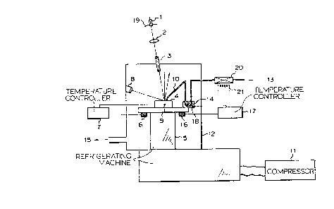
Light which is emitted from a light source 1 is
converged in the form o~ parallel rays by a parabolic mirror
19 and then applied to a mirror surface 4 through an
entrance window 3 after passing throu~h a condenser lens 2
so that the parallel rays are condensed on the mirror
surface 4 as much as possible. The mirror surface 4 is held
on the cold surface of a helium refrigerating machine 5 with
a thermally adequate degree of contact therewith. The
arrangement is such that -the temperature o~ the mirror
surface 4 is capable of being raised or lowered as desired
by a combination of a heater 6 and a temperature controller
7. The incident light is reflected by the mirror surface 4,
and the light whlch is scattered at the mirror surface 4 is
measured by a photodetector 8 which is installed on an
optical path having an angle which is different from that of
the optical path of the light reflected from the mirror
surface 4. The temperature of the mirror surface 4 is
measured by a thermocouple 9.
A gas which is to be measured is lntroduced as shown
by the reference numeral 13 through a filter 20 which is
formed from a hydrophobic material which can be heated up to
200C such that any particulate foreign matter alone can be
removed. After the gas to be measured has previously been
cooled in a precooler 14 to a ~emperature slightly higher
than that of the mirror surface 4, the gas is blown against
.
' '' ' ~
~ '
1 322867
-10-
the mirror surace 4 from the opening of a nozzle 10 and
then discharged from the system as shown by the reference
numeral 15. Since all the above-described constituent
elements are cooled down to low temperatures, the measuring
chamber needs approprlate heat insulating means (including a
vacuum).
The mtrror surface 4 is preferably made of a material
having a thermal conductivity which is as high as possible,
for example, copper, brass, aluminum or silicon crystal.
The mirror surface 4 should be ground as smooth as possible
and the surface precision is prefzrably determined so as to
correspond to 1/4 or less of the wavelength A of the light
source. These are requirements which must be met in order
to minimize the light scattered at the mirror surface 4 and
to allow precise detection of any increase in the intensity
of scattered light caused by freezing of a very small amount
of moisture at the freezing point. Further, it is important
that the incident light be focused on the mirror surface ~
as precisely as possible. The present inventors have found
experimentally that employment of a ray of light which is
itself condensed, such as helium-neon laser light, is, of
course, one of the means that can be used for effectively
improving the sensitivity.
In addition, increasing the reflectivity of the
mirror surface 4 by deposition of gold or aluminum is, of
course, one of the effective means for increasing the
sensitlvity. It is also a matter of course that improving
the hardness of the mirror surface 4 by coating it with a
thin film of titanium nitride, aluminum nitride, silicon
: . - . . . . ..
`
.
:~
,
1 3~2867
--11--
oxide, aluminum oxide or the like is one of the effective
means for maintaining the smooth surface condition of the
mirror surface 4 for a long period of time. Since silicon
wafer is a good helium-neon laser light absorbing material,
its surface is not a good reflecting surface. However, the
surface smoothness of sillcon wafer is considerably high;
according to the experiment carried out b~ the present
inventors, it was possible to m~asure a dsw point near
-120C. From this point of view, a high reflectivity is
not an absolutely necessary condition. In order to measure
effectively a very low water content in even a gas having a
dew point of -80C or less on the basis of the frosting
point, it is absolutely necessary to apply condensed light
to that position on the mirror surface 4 where the gas to be
measured is blown from the nozzle 10. The present tnventors
measured the incident angle of light under various
conditions and, as a result, have ound that, as the
`incident angle becomes closer to 0 with respect to a line
perpendicular to the mirror surface 4, the degree of
sensitivity with which a sudden change in the intensity of
scattered light can be read becomes higher. When a light-
emitting diode is employed as the light source 1, the
sensitivlty becomes higher as the incident angle becomes
closer to 0 with respect to the line perpendicular to the
mirror surface 4, as shown in Fig. 4. The results of the
measurement show that, as the incident angle becomes closer
to 0 with respect to the perpendicular, more condensed
light is applied to the mirror surface 4. It has been shown
1 3~2867
-12~
that the incident angle is preferably set at 60 or less,
particularly preferably, 10 or less.
In order to enable measurement of a very low water
content, it is essential to heat the sampling piping by
means of a heater. With a view to precisely measuring a
very low water content by the dew (~rosting) point method,
it is particularly important to heat the gas to a
temperature near 200C together with a filter which is
capable of removing foreign particles flowing together with
the gas and thereby constantly maintain ~he sampling piping
and the like within the system in a condition wherein the
amount of adsorbed water is reduced.
Compressor for the refrigerator is shown at 11. A
hea-ter for the precooler is shown at 16. A temperature
controller or the precooler is shown at 17. A thermocouple
for the precooler is shown at 18. A heater for the heating
filter is shown at 21.
The present invention will be explained mare speci-
fically below by way of Examples. However, the present
invention is in no way restricted to these Examples.
E~ample 1:
With the arrangement shown in Fig. 1, a gas generated
from liquid nitrogen by ~vaporation was supplied as the gas
to be measured to the mirror sur~ace 4 from the noz~le 10,
light from the light-emitting diode 1 that had been
condensed as much as possible by the parabolic mirror l9 and
the condenser lens 2 then being projected on the mirror 4,
and the light scattered at the mirror surface 4 received by
the photodetector 8. AS the mirror surface 4 was ~radually
',
~'
~ .
1 322~67
-13-
cooled by means of the small-sized helium refrigerating
machine 5, moisture contained in the gas to be measured
became frozen on the mirror surface 4, resulting in an
increase in the intensity of the scattered light received by
the photodetector 8. The temperature of the mirror surface
4 at this time was measured by means of the thermocouple 9.
The temperature was -118C, and thus the dew point of this
gas was found to be -118C. ~hus, it was possible to
measure a dew point so low that it had heretofore been
impossible to measure. The relationship between the
temperature of the mirror surface 4 and the output of the
photodetector 8 is shown by the line a in Fig~ 3. It should
be noted that a silicon wafer employed in the semiconductor
industry was employed in this Example as the mirror surface,
and the light from the light-emitting diode that was
condensed as much as possible was made incident on the
; mirror surface at 5 with respect to the perpendicular.
Example 2:
An experiment was conducted with the same arrangement
as in Example 1 except that the light-emitting diode l and
the parabolic mirror 2 were installed inside the measuring
chamber 12 as shown in Fig. 2. In such a case, since the
temperature inside the chamber 12 changes, the luminance of
the light-emitting diode 1 changes, and this may hinder
precise measurement of the scattered light by means of the
photodetector 8. The small-sized helium refrigerating
machine 5 and the light-emitting diode 1 were therefore
brought into th0rmal contact with each other by the use of
an appropriate copper wire 22, and the temperature of the
. : .
:: :
.
1 3~2~7
-14-
light-emitting diode 1 was maintained at a constant
temperature, i.e., -20C, by temperature control effected by
means of a heater 23, thereby preventing any change in the
luminance of the light-emitting diode 1 due to temperature
changes. ~ith this arrangement, an experiment similar to
that in Example 1 was carried out. As a result, it was
possible to conduct measurement with a higher sensitivity
than that in the case of Example 1. The line b in Fig. 3
shows the relationship between the temperature o~ the mirror
sur~ace 4 and -the output of the photodetector 8. Thus, it
was confirmed that the arrangement shown in Fig. 2 also
enables precise measurement o~ a low dew point, i.e., -80C
or less.
Comparative E~ample 1:
~ith the arrangement of Example 1, a copper surface
was ground so that the surface precision corresponded to the
measuring wavelength A (A = 10.6 ~m), and light from the
light~emitting diode l that was condensed as much as
possible was projected on the mirror surface 4 in the same
way as in Example 1. As a result, even when the moisture
contained in a gas to be measured had not yet ~rozen, the
intensity of the scattered light was higher than that
measured when the moisture became frozen in Example 1.
Further, even when the moisture became frozen, there was no
change in the output of the photodetector 8. Similar
experiments were conducted with the surface prscision of the
copper sur~ace serving as a cooled mirror sur~ace changed to
varying degrees. The results, showed that it is impossible
to measure the dew point (e.g., -120C) o~ a gas containing
.
..
-15- l 32~867
an extremely small amount of moisture when the surface
precision corresponds to 1/4 or more of the measuring
waveleng-th A (A = 10.6 ym). Fig. 5 shows changes in the
output of the photodetector 8 occurring when the surface
precision was changed from ~ (A - 10.6 ym) to A/4.
Comparative Example ~:
E~periments similar to Example 1 were conducted with
the same arrangement as in Example 1 except that the
parabolic mirror 19 and the condenser lens 2 were removed
from the arrangement shown in Fig. 1.
When the light ~rom the light-emitting diode 1 was
not focused on the mirror surface 4, it was possible to
measure a dew point as low as -78C, but it was impossible
to detect an inarease in the intensity of the scattered
light in the case of moisture-containing gases having
respective dew points lower than -78C. Figs. 6 and 7 show
results obtained in the case where the dew points of the
gases tested were -120C and -78C, respectively. As will
be understood from these figures, in order to measure a low
dew point, i.e., -80C or less, the light which is projected
on the mirror surface 4 must be condensed as much as
possible.
Comparative Example 3:
Experiments similar to Example 1 were conducted with
the same arrangement as in Example 1 except that the
photodetector 8 was installed in the optical path of the
reflected ray. Helium-neon laser light and light from a
light-emitting diode that was condensed as much as possible
were employed as the light projected on the mirror surface
: ~ ~. ;: . . - : . : ,
-16- l 322867
4. In thi~ case, the decrease in the intensity of the
reflected light was very small irrespective of the type of
light source. The results of these experiments are shown in
Figs. 8 and 9. It will be understood from these results
that, ln the case where a dew (frosting) point is measured
by detecting a decreaso in the intensity of the reflected
light, it is impossible to measure a dew (~rosting) point of
-75C or less.
Comparative Example 4:
One method which does not employ the technique of
measuring the amount of moisture contained in a gas by
causing the gas to become attached to a mirror surface by
condensation of freezing to allow optical detection o~ the
attached condensate or ice is the method wherein the water
content of a gas is measured on the basis o changes in the
electrostatic capacity of a sensor comprising a thin film of
aluminum oxide which is coated with gold by deposition.
This known method is shown in JIS-K0226 as a method of
measuring a water content of 2 [ppm~ or more. With this
method, nitrogen gases having respective dew points of from
0C to -90C were measured. The results showed that no
change was to be seen in tha electrostatic capacity in the
case of nitrogen gases having dew points of -80C or less.
Fi~. 10 shows a comparison between the output of the
electrostatic condenser type hygrometer and the
- output of the watar content m~asurlng apparatus according to
~ the present invention.
. .,
. ~
.. , , , ,
.
-
- :
, . , .:
. :'
'. . '.
1 322367
-17-
As has been described in detail, the apparatus
according to the present invention is provided with a pre-
cooling section for previously cooling a gas to be measured
before it is blown against a mirror surface and a nozzle for
blowing the precooled gas against the mirror surface.
Further, a light ray which is condensed as much as possible
is employed as a light source to be pro~ected onto the
mirror surface, and the condition of moisture condensed or
frozen on the mirror surface is detected by the light
scattered at the mirror surface. Thus, it is possible to
measure electrically and precisely the water content of a
gas having a dew point in the range of fxom ordinary
temperature to 80C or less.
'', '