Note: Descriptions are shown in the official language in which they were submitted.
1 ~2~q 1 7
"HYPODERMIC NEEDLE SHIELD"
BACKGROUND OF THE INVENTION
This invention relates to a hypodermic needle
shield.
Hypodermic needles are used in many fields and by
medical, nursing, dental, veterinary and other personnel.
Generally it is necessary after the use of a hypodermic
needle to ensure that it is properly sheathed within a
cylindrical container so that it is not exposed.
The need to resheath hypodermic needles in the
protective guard or sheath currently available is well
recognized. Principally the basis of this need is firstly to
ensure that the needle is maintained in a clean or sterile
condition when intermittent use is required and secondly to
provide protection from accidental wounding or pricking of
the operator and other~ near by as may occur whenever a
needle i9 left exposed outside moments of intended and actual
use. Most unfortunately, the act of replacing a hypodermic
needle in its guard or sheath is an occasion of particular
risk for the operator since the sheath provides a small
target at its open end and, if missed, stab wounding of the
fingers is likely. This constitutes an extremely serious
event in all instances where the needle tip is contaminated.
Operator awareness of this personal risk moreover often means
that the needles may be purposely left unsheathed.
In view of recent increased risks of contracting
1 32~ 1 7
-- 2 --
serious diseases by pricking with contaminated needles,
hospitals often implement complex procedures to be undertaken
whenever an inadvertent pricking or wounding of this type
takes place. Even beyond hazards to the operator, therefore,
there arises the serious loss of time which occurs in
following the procedure whenever such an event takes place.
Conventionally a needle, its base for attachment to
the required medical equipment, and a sheath surrounding the
needle which connects to the base is supplied as a single
packaged item for single time usage and then disposal as a
throw away item. In all cases, however, it is necessary for
the needle when used to be re-sheathed so that it cannot
inadvertently protrude and cause pricking of an unsuspecting
person.
Attempts have been made to design a shield device
which can be used to protect the fingers of the operator when
resheathing a needle.
United State~ pa~ent 4,596,562 (Vernon), 4,737,149
(Gillilan) and 4,717,386 (Simmons) disclose arrangements in
which a flat plate member includes an opening into which the
sheath can initially be placed following which the needle is
reinserted into the sheath while the hands of the operator
are protected behind the flat plate.
United States patent 4,654,034 (Masters) discloses
a modified shield in which there is provided a mouth of
increased diameter with a conical portion leading into the
1 322q 1 7
shield so that the needle is better guided into the shield in
the event of a slight inaccuracy by the operator.
United States patent 4,742,910 (Staebler) provides
a needle sheath holder which includes a cylindrical hollow
body into which the conventional sheath is inserted with
suitable grip mechanisms being provided at the mouth of the
cylindrical body. Surrounding the mouth is a flat plate type
shield which is attached to the cylindrical body.
None of these devices has apparently achieved
commercial success since in the field the problem remains
unresolved. The reasons for the non-acceptance of the above
proposals is not entirely clear but possibly this relates to
the necessity of the additional devices of Vernon, Simmons,
Gillilan and Staebler to modify the conventional handling
techniques of the packaged and supplied disposable needle,
needle sheath and needle base. These devices are not
intended to be disposable or throw away items and thus must
be removed from the sheath in a separate process thus
reducing the efficiency of handling. The Masters device
provides only limited protection since it merely increases
the size of the mouth leaving the fingers still partly
exposed to the danger of pricking and thus cannot be
considered to be a satisfactory solution.
SUMMARY OF THE INVENTION
It is one object of the present invention,
therefore, to provide an improved shield device for use with
```` 1 3229 1 7
-- 4
a hypodermic needle which enables the device to be used as a
disposable item so that it can follow the conventional
handling techniques used with the conventional sheaths
currently available.
According to the invention, therefore, there is
provided a shield device for use in sheathing a medical
needle of the type comprising an elongate hollow needle and a
base on which the needle is mounted, said shield device
comprising a central body including a hollow cylindrical body
portion defining an open mouth at one end into which the
needle can be inserted so that it extends axially along the
interior of the body portion with the base of the needle
outside the open mouth, a shield members having a central
strip portion with two parallel sides and having a width
between the sides at least equal to the width of the
cylindrical body portion and a length such that the strip
portion extends outwardly from the central body to respective
sides thereof and two flat flap members each mounted on the
central strip portion for pivotal movement about a hinge line
along a respective side of the central strip portion adjacent
to the open mouth from a first retracted position in which
the flap members lie substantially parallel on opposed sides
of said cylindrical body portion to a second deployed
position in which the flap members project outwardly from the
the central strip portion, the two flap members and the
central strip portion being shaped to define in cooperation a
~, s"
1 ~ 2 ~ 9 1 7
protective plate fully surrounding said open mouth, and means
for latching the flap members in the retracted position.
The invention thus provides a device which can be
used to overcome or minimize the problems stated above. In
particular the device can be manufactured as a disposable
item which can be supplied in packaged form with the needle
. ~ ~
1 32~9 1 7
and needle base since the folded flap members in the
retracted position enable the device to be readily packaged.
The initial packaged position with the flap members
retracted allows the operator largely unobstructed visibility
as is necessary for best needle selection. Color coding of
the present invention offers the use of identifying data on
the device and can assist the needle selection process.
Once selected the device provides the operator with
an improved and flat needle container to grasp, in comparison
with prior art cylindrically shaped needle sheaths. The
needle base can be attached to the necessary syringe or other
medical equipment in the conventional manner.
Preferably squeezing of the flap members alone is
required to trigger the device to move to the deployed
position as soon as the operator's finger grip is released.
Thus no decision or conscious effort is involved beyond that
which is conventional and long established and familiar with
operators from the conventional prior art needle guards.
In the deployed position, the device offers ready
advantage for resheathing of the needle. Left by itself, its
larger than prior art dimensions mean that it is unlikely to
be misplaced or lost; neither will it roll away. Placed on a
level surface, moreover, the device elevates the opening for
needle reinsertion to a convenient angle and view simplifying
this action to a large extent compared to conventional needle
1 322q 1 7
-- 6 --
sheaths. Alternatively if the operator chooses to grasp the
present invention in one hand while resheathing the needle,
this may be done easily and safely since the flap member~
provide the necessary protection.
In one embodiment, the cylindrical body can
comprise simply a collar within which a conventional needle
sheath is inserted. Thus the device is then manufactured as
a separate unit preferably integrally molded from a suitable
plastics material, and attached to the conventional needle
sheath before packaging of the device, the needle sheath,
needle and needle base as an individually supplied and
disposable item. In an second embodiment, the needle sheath
and the cylindrical body are formed as an integral
construction for insertion of the conventional needle and
needle base.
Preferably the flap members are biased to the
deployed position by a steel coil spring which can be mounted
upon a suitable hook on the side of the cylindrical body.
Additional forces to bias the flap members to the deployed
po~ition can be provided by the molded hinges which retain
sufficient memory to provide some bia~ing force. In addition
the positioning of the operator's finger behind the flap
members on the cylindrical body will act to provide a force
moving the flap members to the deployed position so that in
the unlikely event that the coil spring fails, the device
1 3Z2q 1 7
remains operable with the need for only limited operator
assistance.
The latch means is preferably of a type which
maintains the flap members latched in the retracted position
but is immediately released upon the operator squeezing the
two flaps closer together while grasping the device thus
increasing momentarily the nominal tension in the coil
spring. Such squeezing is generally necessary to affix the
needle base to its syringe or other medical attachment so
that this conventional and normal action of the operator
releases the latch mechanism so that as the needle and needle
base are withdrawn, the flap members are automatically
released into the deployed position.
According to a second aspect of the invention there
is provided a disposable hypodermic needle assembly
comprising an elongate hollow needle, a base on which the
needle is mounted, a cylindrical needle sheath having an open
mouth at one end for receiving the needle fed therein and for
cooperating with the needle base to hold the needle in place,
and a shield device comprising a central body including a
hollow cylindrical body portion into which the sheath is
inserted as a sliding fit, shield members having a central
strip portion with two parallel sides and having a width
between the sides at least equal to the width of the
cylindrical body portion and a length such that the strip
portion extends outwardly from the central body to respective
. . .~
1 322q 1 7
- 7A -
sides thereof and two flat flap members each mounted on the
central strip portion for pivotal movement about a hinge line
along a respective side of the central strip portion adjacent
to the open mouth of the sheath from a first retracted
position in which the flap members lie substantially parallel
on opposed sides of said cylindrical body portion to a second
deployed position in which the flap members project outwardly
from the the central strip portion, the two flap members and
the central strip portion being shaped to define in
cooperation a protective plate fully surrounding said open
mouth spring means biasing said flap members to said deployed
position and means for latching the flap members in the
retracted position, said central body, said central strip
portion and said flap members being integrally molded from a
plastics material.
According to a third aspect of the invention there
is provided a disposable hypodermic needle assembly
comprising an elongate hollow needle, a base on which the
needle is mounted, and a needle sheathing and shield device
comprising a central body including a hollow cylindrical body
portion defining an open mouth at one end into which the
needle can be inserted so that it extends axially along the
interior of the body portion with the base of the needle
cooperating with the open mouth to retain the needle in
position, shield members having a central strip portion with
two parallel sides and having a width between the sides at
.
1 3229 1 7
- 7B -
least equal to the width of the cylindrical body portion and
a length such that the strip portion extends outwardly from
the central body to respective sides thereof and two flat
flap members each mounted on the center strip portion for
pivotal movement about a hinge line adjacent to the open
mouth along a respective side of the strip portion from a
first retracted position in which the flap members lie
substantially parallel on opposed sides of said cylindrical
body portion to a second deployed position in which the flap
members project outwardly from the the central strip portion,
the two flap members and the central strip portion being
shaped to define in cooperation a protective plate fully
surrounding said open mouth, means biassing said flap members
to the deployed position and means for latching the flap
members in the retracted position, said central body portion,
said central strip portion and said flap members being
integrally molded from a plastics material.
With the foregoing in view, and other advantages as
will become apparent to those skilled in the art to which
this invention relates as this specification proceeds, the
invention is herein described by reference to the
accompanying drawings forming a part hereof, which includes a
description of the best mode known to the applicant and of
the preferred typical embodiment of the principles of the
present invention, in which:
" 1 3229 1 7
- 7C -
DESCRIPTION OF THE DRAWINGS
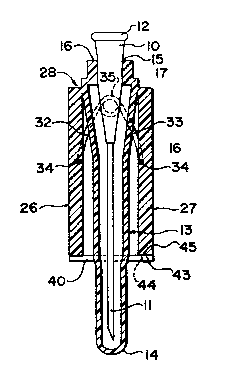
Figure 1 is a cross sectional view showing a
needle, needle base and needle sheath incorporating a shield
arrangement in a retracted position thereof according to the
invention.
. r~'
~ ~? 2q 1 7
-- 8 --
Figure 2 is a cross sectional view similar to
Figure 1 of an alternative embodiment in which the needle
sheath is separate from the shield device, the shield device
being in the deployed position.
Figure 3 is a top plan view of the shield device of
Figure 2 with the needle sheath removed.
Figure 4 is an underside view of the shield device
of Figure 3 in the retracted position.
In the drawings like characters of reference
indicate corresponding parts in the different figures.
DETAILED DESCRIPTION
In Figure 1 there is shown a conventional needle
assembly comprising a needle base 10 and a hollow hypodermic
needle 11. The bas~ includes the conventional screw lock
flange 12 by which it can be attached to a suitable medical
appliance for example a syringe. As these devices are of a
conventional nature, they are not shown in detail.
In Figure 1 the needle assembly is shown mounted
within a sheath generally indicated at 13. The sheath
comprises a hollow cylindrical body having a closed lower end
14 and an open mouth 15 so that the needle can be inserted
into the hollow body to a position in which the needle base
10 cooperates as a press fit with an inner surface of the
hollow body at the open mouth to hold the needle assembly in
position within the sheath.
1 322q 1 7
In the embodiment of Figure 1, the sheath 13 is a
continuous unitary body extending from the closed end 14
through to the open mouth 15. A portion 16 is flared
slightly outwardly toward the open mouth so as to define
shoulders 17 of increased transverse dimension relative to an
end face 16 of the sheath.
In Figure 2 the sheath generally indicated at 13 is
formed of two separate parts. Firstly there is provided a
conventional sheath 18 which includes a cylindrical hollow
body with a closed lower end as previously described which is
substantially of constant diameter except for a flange 19 at
an upper end. Such sheaths are entirely conventional. In
this embodiment the conventional sheath 18 is received within
a cylindrical receiving sleeve 20 which defines an inner
qurface 21 dimensioned to receive the outer surface of the
sheath 18 as a sliding fit. The sleeve 20 includes an open
end 22 against which the underside of the flange 19 sits. An
outer surface of the sleeve 20 tapers as indicated at 23
toward a lower open end 24. The length of the sleeve 20 is
less than that of the sheath 18 and the lower end 24 is open
so that sheaths of different lengths can be received within
the sleeve 20 depending upon requirements.
For convenience of illustration only the embodiment
of Figure 2 is shown in the plan view of Figure 3 and the
underside view of Figure 4 but it will be appreciated that
the embodiment of Figure 1 is substantially identical to that
1 322q t 7
-- 10 --
shown in Figures 3 and 4 except for the integrated
constructicn of the sleeve and sheath.
As shown in Figures 3 and 4, the upper face 22 of
the sleeve forms part of an elongate strip 25 which in the
transverse direction shown in Figure 2 is of only narrow
width only slightly greater than the diameter of the open end
of the sleeve 20. In the longitudinal direction shown in
Figures 3 and 4, the plate 25 is elongated so as to form a
length of the order of two to three inches. On either side
of the central plate 25 is formed a respective one of a pair
of flap members 26 and 27 each of which has a length equal to
the length of the plate 25 and a width of the order of one to
two inches. As shown in Figure 3, in the deployed position,
the flap members 26 and 27 cooperate with the plate 25 to
form a substantially rectangular shield plate. The shape of
the outer edges can be varied to provide various esthetic
effects and the upper surface can include a design or pattern
again for an attractive appearance. The dimensions of the
plate are therefore of the order of two to four inches in
width and length.
The flap members 26 and 27 are attached to the
central plate 25 by molded hinge members 28 which are formed
by molding a cut line 29 shown in Figure 2 leaving a small
sec~ion 30 of the plastics material from which the device is
molded which i9 sufficiently thin to allow flexing of the
flap members about the hinge line defined by the material 30
1 3229 1 7
11
while providing sufficient strength at that point to avoid
tearing of the flap members from the central plate. The
device can be molded so that the plastics material retains a
memory tending to return the flap members to the deployed
position shown in Figures 2 and 3.
A spring 31 provides a biasing force on the flap
members tending to move them to the deployed position shown
in Figure 2. Thus the spring 31 includes a pair of spring
arms 32 and 33 each of which includes a right angle portion
34 for engaging an under surface of the respective flap
member. From the right angled portion, each arm extend~
inwardly to a central coil section 35 which is mounted upon a
projection or nose 36 molded onto the outer surface of the
sleeve 20. The projection 36 thu~ provides a fixed support
for the coil 35 which is torsioned to bias the arms 32 and 33
outwardly from the retracted position shown in Figure
toward the deploysd position shown in Figure 2. The spring
can be applied into the mold during the molding of the device
so that it is attached and integrated with the unit in the
molding process.
A latching arrangement is provided to hold the flap
members in the retracted po~ition as shown in Figures 1 and
4. The latching arrangement comprises a pair of straps 40
and 41 which are attached to one edge of the flap member 26
remote from the hinge line thereof. The straps 40, 41 are
integrally molded with the flap member 26 and are molded so
1 3229 1 7
- 12 -
as to have a memory tending to spring them away from a
position at right angles to the flap member to the position
illustrated in Figure 2. In the latched position, each of
the straps 40, 41 cooperates with a male projection 43
provided on the edge of the other flap member 27. Thus in
the retracted position shown in Figure 1, the male member 43
projects downwardly and it is also inclined in a direction
away from the other flap member so that it can cooperate with
an opening 44 provided in the strap 40, 41 to hold the flap
members in the retracted position shown. As the flap members
are under spring tension tending to move them apart, out of
the retracted position, the inclination of the male member 43
away from the other flap member tends to pull the edge of the
opening 44 into the V-shaped area between the male member 43
and the outer edge 45 of the flap member 27. The sides of
the opening 44 can be inclined in the same direction as the
projecting male member 43 so as to cooperate in retaining the
latched position.
In operation, the device in the retracted latched
position shown in Figures 1 and 4 is assembled with the
needle assembly (and the separate sheath in the embodiment of
Figures 2, 3 and 4) so as to form the complete assembly as
shown in Figure 1. The completed assembly is then packaged
in suitable materials generally of a transparent nature to
allow inspection of the contents for needle selection. When
the needle is required for use, the packaging is opened and
1 3229 1 7
- 13 -
the assembly removed for use. During the use, the sides of
the flap members are grasped by the operator so that the
needle base can be attached by the flange 12 to the required
medical equipment. The shield and flap members are then
pulled away from the needle so that the needle is removed
from the sheath for use. The squeezing effect necessary to
complete the attachment of the needle base to the equipment
and to remove the needle from the sheath is sufficient to
cause the flap members to move more closely together at the
ends thereof remote from the hinge lines. As the edge of the
flap member 27 moves toward the flap member 26, the edges of
the opening 44 force the opening away from the projecting
male member 43 so that it is released from the male member
and allowed to spring open away from the edge of the flap
member 27 under the spring force to take up the outwardly
extended position at an angle slightly greater than right
angles as shown in Figure 2. Subsequent release of the
compression of the flap members by the operator then allows
the flap members to move to the deployed position shown in
Figure 2 under the spring force provided by the spring 31 and
by the memory in the molded plastics material and, if
necessary, by finger force provided on the rear of the flap
members by the operator's fingers grasping the device behind
the flap members.
When deployed therefore the shield and sheath
assembly can simply be placed upon a suitable surface and
1 3229 1 7
- 14 -
left to stand without any danger of it rolling away or being
misplaced in view of its relatively large dimensions.
When the use of the needle is complete, the needle
can be returned to its sheathed position. In one mode of
operation, the device can be left sitting on the surface with
one edge of the shield defined by the flap members 26, 27 and
the central plate 25 resting upon the surface with a further
point of contact on the surface being provided by the lower
end 14 of the sheath. This inclines the sheath away from the
surface so that the needle can simply be placed into the
sheath without the necessity for the operator to touch the
sheath and shield assembly. In a further mode, the operator
can grasp the sheath and shield assembly at the sheath behind
the shield so that the shield plate protects the fingers of
the user as the needle is moved toward the open mouth of the
sheath.
The device is intended as a disposable device so
that when the needle has been used and resheathed, the whole
unit is thrown away for disposal leaving the flap members in
the deployed position.
Since various modifications can be made in my
invention as hereinabove dPscribed, and many apparently
widely different embodiments of same made within the spirit
and scope of the claims without departing from such spirit
and scope, it is intended that all matter contained in the
accompanying specification shall be interpreted as
illustrative only and not in a limiting sense.