Language selection

Search

Patent 1322970 Summary

Third-party information liability

Some of the information on this Web page has been provided by external sources. The Government of Canada is not responsible for the accuracy, reliability or currency of the information supplied by external sources. Users wishing to rely upon this information should consult directly with the source of the information. Content provided by external sources is not subject to official languages, privacy and accessibility requirements.

Claims and Abstract availability

Any discrepancies in the text and image of the Claims and Abstract are due to differing posting times. Text of the Claims and Abstract are posted:

  • At the time the application is open to public inspection;
  • At the time of issue of the patent (grant).
(12) Patent: (11) CA 1322970
(21) Application Number: 1322970
(54) English Title: ADAPTOR FOR ALLOWING DIFFERENT GEL BED HEIGHTS IN A CHROMATOGRAPHIC SEPARATION COLUMN
(54) French Title: ADAPTEUR PERMETTANT D'OBTENIR DIVERSES HAUTEURS DE LIT DE GEL DANS UNE COLONNE DE SEPARATION CHROMATOGRAPHIQUE
Status: Expired and beyond the Period of Reversal
Bibliographic Data
(51) International Patent Classification (IPC):
  • B01D 15/08 (2006.01)
  • G01N 30/00 (2006.01)
  • G01N 30/10 (2006.01)
  • G01N 30/16 (2006.01)
  • G01N 30/26 (2006.01)
  • G01N 30/52 (2006.01)
  • G01N 30/56 (2006.01)
  • G01N 30/60 (2006.01)
(72) Inventors :
  • LARSSON, LARS-ANDERS (Sweden)
(73) Owners :
  • PHARMACIA BIOTECH AB
(71) Applicants :
  • PHARMACIA BIOTECH AB (Sweden)
(74) Agent: SMART & BIGGAR LP
(74) Associate agent:
(45) Issued: 1993-10-12
(22) Filed Date: 1989-02-03
Availability of licence: N/A
Dedicated to the Public: N/A
(25) Language of filing: English

Patent Cooperation Treaty (PCT): No

(30) Application Priority Data:
Application No. Country/Territory Date
8800644-0 (Sweden) 1988-02-25

Abstracts

English Abstract


ABSTRACT
To allow different gel bed heights in a chromatographic
separation column (1), a plunger (6) is displaceable within the
column (1) into contact with the gel bed (5) by means of a shaft
(7) extending through an end piece (3) at the end of the column
(1), said end piece (3) having a locking means for locking the
shaft (7). According to the invention said locking means
comprises a resiliently biassed locking piece (8) having grooves
extending essentially perpendicular to the longitudinal
direction of the shaft (7) which grooves engage corresponding
grooves on the shaft (7) in the normal position of the locking
piece (8). In its normal position, the locking piece (8) is
adapted to allow displacement of the shaft (7) only towards the
gel bed (5). Moreover, the locking piece (8) is manually
operable from its normal position to allow free displacement of
the shaft (7).


Claims

Note: Claims are shown in the official language in which they were submitted.

- 5 -
THE EMBODIMENTS OF THE INVENTION IN WHICH AN EXCLUSIVE
PROPERTY OR PRIVILEGE IS CLAIMED ARE DEFINED AS FOLLOWS:
1. An adaptor for allowing different gel bed heights in a
chromatographic separation column comprising a plunger
displaceable within the column into contact with the gel
bed by means of a shaft extending through an end piece at
an end of the column, the end piece having a locking means
for locking the shaft comprising a resiliently biassed
locking piece having grooves extending essentially
perpendicular to the longitudinal direction of the shaft,
the grooves engaging corresponding grooves on the shaft in
the normal position of the locking piece, the locking
piece, in its normal position, being adapted to allow
displacement of the shaft only towards the gel bed, and
the locking piece being manually operable from its normal
position to allow free displacement of the shaft.
2. An adaptor according to claim 1, in which the grooves
on both the locking piece and the shaft are threads for
enabling fine adjustment of the plunger relative to the
gel bed by turning the shaft in the end piece.

Description

Note: Descriptions are shown in the official language in which they were submitted.


Adaptor for allowing different gel ~ ~d2h2el9g7tQ in a
chromatographic separation column.
The invention relates to an adaptor for allowing different gel
bed heights in a chromatographic separation column, comprising a
plunger which is displaceable within the column into contact
with the gel bed by means of a shaft extending through an end
piece at the end of the column, said end piece having a locking
means for locking the shaft.
As a locking means it is known to use a screw which extends
radially towards the shaft through the end piece. In this case,
the shaft is locked by the friction between the end of the screw
and the shaft.
However, in columns intended for high pressures such a locking
has not been sufficient. In such columns the plunger is exposed
to great axial forces which can cause a displacement of the
plunger from its set position. This in turn leads to the
formation of an undesirable interspace between the plunger and
the gel bed.
At very large columns it is also known to have a threaded shaft
by means of which the plunger can be screwed towards the gel bed
through a nut provided in the end piece. However, this is a very
time-consuming procedure.
The object of the invention is to bring about an adaptor which
in a quick and simple manner enables a secure setting of the
plunger against the gel bed.
This is attained in that the locking means comprises a
resiliently biassed locking piece having grooves extending
essentially perpendicular to the longitudinal direction of the
shaft, said grooves engaging corresponding grooves on the shaft
in the normal position of the locking piece, said locking piece,
in its normal position, being adapted to allow displacement of ;.
the shaft only towards the gel bed, and said locking piece being

1322970
manually operable from its normal position to allow free
displacement of the shaft.
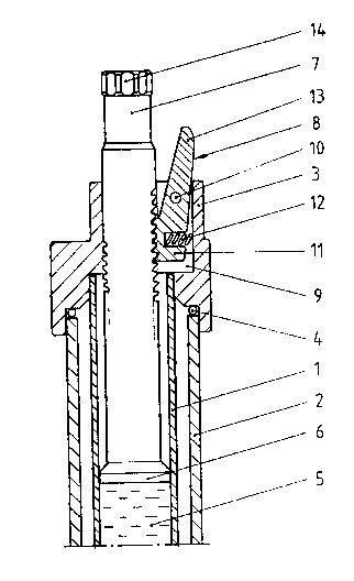
The invention will be described more in detail below with
reference to the attached drawing on which the single figure
shows a longitudinal section of one end of a separation column
provided with an embodiment of an adaptor according to the
invention.
A separation column of a type known per se, is denoted 1. In the
embodiment shown, the separation column 1 is surrounded by a
cooling jacket 2 to enable a cooling medium, e.g. water, to be
fed to and from the interspace between the column 1 and the
jacket 2 in a manner not shown. The end of the column 1 is
received in an end piece 3 which is supposed to be screwed onto
the jacket 2. An O-ring 4 is placed between the upper end of the
jacket 2 and the end piece 3 to seal the jacket 2 and the end
piece 3.
The column 1 is supposed to be filled to a certain level with a
separation gel bed 5. The gel bed 5 is kept in place in the
column 1 by means of a plunger 6 which is displaceable in the
column 1 into contact with the gel bed 5 by means of a shaft
which extends through a center hole in the end piece 3.
In a manner known per se the plunger 6 comprises sealing means
(not shown) for sealing against the inside of the coluon 1 as
well as a support filter (not shown) for the gel bed 5.
In a manner known per se supply means (not shown) extends
through the shaft 7 for supplying a sample to be separated to
the gel bed 5.

1322970
To lock the shaft 7 with the plunger 6 in contact with the gel
bed 5, the end piece 3 comprises a lever-shaped locking piece 8
in a recess 9.
In the embodiment shown, the locking piece 8 is pivoted on a pin
10 extending perpendicular to the longitudinal axis of the shaft
7 within the recess 9.
One arm 11 of the locking piece 8 is provided with threads on a
segment facing the shaft 7. ~y means of a compression spring 12
inserted between the arm 11 and the wall of the recess 9 these
threads are in engagement with corresponding threads on the
shaft 7 in the normal position of the locking piece 8 as shown
on the drawing.
In the embodiment shown the other arm 13 of the locking piece 8
abuts the wall of the recess 9 with a portion facing away from
the shaft 7.
Thus, in the normal position of the locking piece 8 as shown on
the drawing the shaft 7 with the plunger 6 can manually be
displaced towards the gel bed 5 against the action of the
compression spring 12 to quickly and coarsely adjust the
position of the plunger 6. To finely adjust the position of the
plunger 6 the shaft 7 can, then, be screwed into tight contact
with the gel bed 5 by means of a grooved flange 14 at the free
end of the shaft 7.
By manually bringing the arm 13 of the locking piece 8 towards
the shaft 7, the threads of the arm 11 are brought out of
engagement with the threads on the shaft 7 whereby the shaft 7
can be freely displaced in the end piece 3.
Of course, it is not necessary that the engagement between the
arm 11 of the locking piece 8 and the shaft 7 takes place via
threads but the engagement can instead take place via grooves ln

1322970
case one does not want to be able to finely adjust the position
of the plunger 6 in the column 1.
As an alternative to the lever-shaped locking piece 8, any kind
of a resiliently biassed locking piece is possible as long as it
in its normal position allows displacement of the shaft 7 only
towards the gel bed 5. As an example, a push button operated
locking piece can be mentioned, which in one of its positions is
in engagement with the shaft 7 and which in its other position
is out of engagement with the shaft 7. Other embodiments of the
locking piece should be apparent to anyone skilled in the art.
Thus, a quick, simple and exact adjustment of the plunger 6
relative to the gel bed 5 is made possible by means of the
adaptor according to the invention. Also, the plunger may
quickly and simply be removed from the gel bed 5 by pulling out
the shaft 7 after that the arm 13 of the locking piece has been
pressed towards the shaft 7.

Representative Drawing
A single figure which represents the drawing illustrating the invention.
Administrative Status

2024-08-01:As part of the Next Generation Patents (NGP) transition, the Canadian Patents Database (CPD) now contains a more detailed Event History, which replicates the Event Log of our new back-office solution.

Please note that "Inactive:" events refers to events no longer in use in our new back-office solution.

For a clearer understanding of the status of the application/patent presented on this page, the site Disclaimer , as well as the definitions for Patent , Event History , Maintenance Fee  and Payment History  should be consulted.

Event History

Description Date
Time Limit for Reversal Expired 2006-10-12
Inactive: IPC from MCD 2006-03-11
Letter Sent 2005-10-12
Grant by Issuance 1993-10-12

Abandonment History

There is no abandonment history.

Fee History

Fee Type Anniversary Year Due Date Paid Date
MF (category 1, 4th anniv.) - standard 1997-10-14 1997-09-18
MF (category 1, 5th anniv.) - standard 1998-10-13 1998-09-18
MF (category 1, 6th anniv.) - standard 1999-10-12 1999-09-16
MF (category 1, 7th anniv.) - standard 2000-10-12 2000-09-19
MF (category 1, 8th anniv.) - standard 2001-10-12 2001-09-18
MF (category 1, 9th anniv.) - standard 2002-10-14 2002-09-19
MF (category 1, 10th anniv.) - standard 2003-10-13 2003-09-17
MF (category 1, 11th anniv.) - standard 2004-10-12 2004-09-21
Owners on Record

Note: Records showing the ownership history in alphabetical order.

Current Owners on Record
PHARMACIA BIOTECH AB
Past Owners on Record
LARS-ANDERS LARSSON
Past Owners that do not appear in the "Owners on Record" listing will appear in other documentation within the application.
Documents

To view selected files, please enter reCAPTCHA code :


To view images, click a link in the Document Description column. To download the documents, select one or more checkboxes in the first column and then click the "Download Selected in PDF format (Zip Archive)" or the "Download Selected as Single PDF" button.

List of published and non-published patent-specific documents on the CPD .

If you have any difficulty accessing content, you can call the Client Service Centre at 1-866-997-1936 or send them an e-mail at CIPO Client Service Centre.


Document
Description 
Date
(yyyy-mm-dd) 
Number of pages   Size of Image (KB) 
Cover Page 1994-03-08 1 14
Drawings 1994-03-08 1 16
Abstract 1994-03-08 1 15
Claims 1994-03-08 1 27
Descriptions 1994-03-08 4 116
Representative drawing 2000-08-03 1 15
Maintenance Fee Notice 2005-12-07 1 172
Fees 1996-09-19 1 72
Fees 1995-09-18 1 67
Examiner Requisition 1992-07-31 1 50
PCT Correspondence 1993-07-14 1 23
Prosecution correspondence 1992-11-13 3 98