Note: Descriptions are shown in the official language in which they were submitted.
1 3230~ 1
A PROCESS FOR PREPARING ALKYT~ HALIDES
The preparation of alkyl halides, particularly
methyl chloride from the reaction of the corresponding
alcohol with a hydrogen halide i9 known in the art. The
by-products of the reaction are water and the corresponding
dialkyl ether. Most known processes carry out the reaction
with a stoichiometric excess of the hydrogen halide relative
to the alcohol. As such, unreacted hydrogen halide must be
discarded to the environment or recovered and recycled to the
process. The recovery of the hydrogen halide, particularly
hydrogen chloride (HCl) createq many proce~sing difficultieq.
To begin with, HCl forms a minimum boiling azeotrope with
water. Recovery and recycle of HCl is complicated by this
azeotrope. Additionally, the very corrosive nature of
aqueous HCl dictates that handling of this stream be held to
a minimum. Finally, many known processe~ utilize ca~alysts
to promote the reaction.
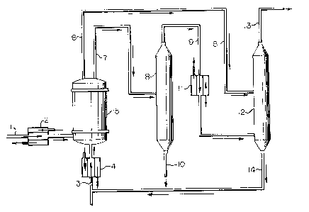
The drawing in Figure 1 is a representation of one
embodiment of the instant invention. This representation is
presented to be illustrative and is not to be construed as
limiting the instant invention. Figure 1 outlines the
process in which aqueous hydrogen chloride and a
stoichiometric excess of methanol are contacted in a liquid
phase in a plug-flow reactor in which backmixing of
reactsnt8, product methyl chloride and by-product water is
minimized. The desired methyl chloride product is separated
and isolated; by-product water is separated from excess
methanol, the water being discarded; and the excess methanol
i~ recovered and recycled to the reactor.
In Figure 1, 1 is the aqueous hydrogen chloride
(HCl) feed to the reactor. 2 is a heat exchanger in which
:, :
.:
.
:;
~ . ,
1 3230 ~ 1
--2--
stream 1 i~ heated. 3 is the methanol feed to the reactor.
4 is a heat exchanger in which ~tream 3 is heated. 5 is a
packed column in which the aqueous HCl, methanol, the product
methyl chloride and the by-product water flow upward through
the reactor in a co-current, plug flow configuration. The
heat input into heat exchangers 2 and 4 controls the
temperature of the reactor 5. The temperature and pressure
within the reactor 5 are controlled so that the reactants
within the reactor are in a liquid, aqueous environment.
Stream 6 is a vapor effluent from the reactor 5 which
consists essentially of methyl chloride, methanol and
by-product dimethyl ether. Stream 7 is a liquid effluent
from the reactor 5 which comprises mainly methanol, water and
a small amount of HGl. 8 is a distillation column in which
methanol and methyl chloride are recovered as an overhead
product stream 9. Stream 10 is a combination of the water
fed with the aqueous HCl and by-product water and a small
amount of HCl. Stream 10 is discarded. 11 is a condenser in
which stream 9 is cooled. Streams 6 and 9 are fed to a
di~tillation column 12 in which product methyl chloride is
recovered as an overhead product stream 13. Excess methanol
is recovered as a bottoms stream 14 from the distillation
column 12. The recovered methanol stream 14 is recycled to
the reactor.
The ob~ective of the instant invention is the
preparation of an alkyl halide from the reaction of the
corresponting alcohol and a hydrogen halide in which
conversion of the hydrogen halide is ma~imized in a single
pass through the reactor, eliminating the need for recovering
and recycling hydrogen halide.
It has been found that high fir~t-pass conversion
of hydrogen halide at high rates of production can be
achieved by using a reactor in which the reactants are fed
.. . . : ~
1 3 2 3 ~ r 1
-3-
co-currently into a plug-flow reactor configuration in which
backmixing is minimized. Further, the reaction takes place
in an aqueous environment without a catalyst. The excess
alcohol can be recovered and recycled to the reactor and a
very dilute stream of aqueous hydrogen halide is discarded.
In accordance with the instant invention, there is
provided a process for the preparation of an alkyl halide
from the corre~ponting alcohol and a hydrogen halide under
conditions that will be delineated herein. What is
described, therefore, is a process for preparation of an
alkyl halide, RX, from reaction between the corresponding
alcohol, ROH and a hydrogen halide, HX, ln the absence of a
catalyst, said process improving conver~ion o$ the hydrogen
halide to the alkyl halide in a single psss through a
reactor, wherein R is an alkyl group containing from 1 to 4
carbon atoms; and wherein X is a halogen atom; said process
comprising
(A) contacting and reacting the hydrogen halide
with a stoichiometric excess of the alcohol in
a plug-flow reactor in which flow of a mixture
comprising unreacted alcohol, unreacted
hydrogen halide, the alkyl halide and water is
co-current; wherein the temperature within the
reactor is greater than about 100C., and the
pressure within the reactor i~ in a range from
about 15 to lSO psig to maintain a liquid,
aqueous medium in the reactor; and
(B) isolating and separating the alkyl halide.
The reaction of an alcohol with a hydrogen halide
can be repre8ented as,
ROH + HX = RX + H20 (1) .
Additionally, dialkyl ether can form as a by-product by the
reaction,
: - , .
.,j : . ~ .
. . . . , . - .: . : .
, . . .
. . ,-, . ... . .
,
- ~ , -
::.
1 ~ 2 3 0 llr 1
R~H + ROH = R20 + H20 (2).
The alcohol utilized in the instant invention can
be, for example, methanol, ethanol, n-propanol, i-propanol,
n-butanol, sec-butanol or t-butanol. The alcohol can be
brought to the reactor as a liquid by known means such as
pumping. The alcohol may also be vaporized by conventional
mean~ and fed to the reactor as a vapor. The alcohol can be
fed to the reactor as a vapor or liquid at multiple feed
points or at ~ust one point.
The hydrogen halide, utilized in the instant
invention, can be, for example, hydrogen fluoride, hydrogen
chloride, hydrogen bromide or hydrogen iodide. Hydragen
chloride is the preferred hydrogen halide. The hydrogen
halide can be fed as an aqueous solution or as an anhydrous
gas. Aqueous hydrogen halide can be fed to the reactor by
conventional means for tran~porting liquids such as pumping.
The anhydrous HCl can be fed to the reactor by conventional
means for transportlng gases. For the purposes of the
instant invention, the term "essentially anhydrous hydrogen
halide" refers to a stream with only trace amounts of water,
as, for example, in the range 1000 ppm water or le~s.
The product alkyl halide can be, for example,
methyl chloride, methyl bromide, ethyl fluoride, ethyl
chloride, n-propyl chloride, n-propyl iodide, i-butyl
chloride or t-butyl chloride.
Unlike much of the prior art, the reaction of the
alcohol and the hydrogen halide to produce the alkyl halide
i~ effected in the absence of any catalyst, as for example,
metal halide salts, activated alumina, etc.
The alcohol and the hydrogen halide are contacted
in a plug-flow reactor (PFR) in which the flow of reactants
and subsequent products and by-product~ is co-current. As
known in the art, in a PFR there is essentially no mixing in
.
~ . !
I 323~ 1
the direction of flow, but with some mixing in the transverse
direction. Therefore, there is a concentration 8radient of
reactants between the feet end and exit end of the reactor.
In comparison, in a back-mixed reactor or continuous stirred
tank reactor (CSTR), used extensively in the preparation of
alkyl halides, the reactants, products and by-products are
totally mixed and essentially no concentration gradient
exists in the reactor. Reaction rate generally depends upon
concentration of reactants. The PFR configuration takes
advantage of the higher rates corresponding to the higher
concentration of reactants at the feed end of the reactor.
Therefore, the PFR will require a smaller reactor volume,
shorter residence time, than that required for the more
conventional CSTR.
The PFR can be, for example, known reactor
configurations such as a packed bed, a tray-type column or a
series of small CSTR's with separation between reactors.
It has been found that feeding a stoichiometric
exce88 of an alcohol relative to a hydrogen halide
9ignificantly improved the conversion of the hydrogen halide
to the tesired alkyl halide. It is preferred that the
stoichiometric excess of the alcohol relative to the hydrogen
halide be greater than about 10 mole percent to gain benefit
from the instant invention. It is more preferred that the
stoichiometric exce~s of the alcohol be in a range from about
20 to 200 mole percent. This preferred range gives a
sati8factory balance between increased conversion of hydrogen
halide to alkyl halide and the generation of by-product
dialkyl ether. Hytrogen halide conversion to the desired
alkyl halide has been found to increase from about 70 percent
to a~ much as 95 percent. It is understood that lower
stoichiometric excesses of alcohol approaching a
8toichiometric balance can be utilized, however, with minimum
,,
;: '- .. ,`. : ~ ~' `' '
1 3? 3 () !1 1
--6--
increase in hydrogen halide conver~ion. It i9 further
understood that stoichiometric exces~es greater than 200 mole
percent can be utilized, however, with potentially
significant increases in the production of by-product dialkyl
ether. However, it has been found that within the preferred
range of stoichiometric excess of the alcohol and the
reaction conditions disclosed by the instant invention the
formation of dialkyl ether is acceptable and does not cause a
significant raw material utilization or cost penalty.
Thus, the use of a stoichiometric excess of
alcohol, as described above, facilitates improved conversion
of hydrogen halide to the desired alkyl halide. Conversion
of hydrogen halide is complete enough 80 that what hydrogen
halide remains can be discarded without ~ignificant economic
penalty. Thus, the desired conversion oE the hydrogen halide
is effected in a single-pass through the plug-flow reactor.
The reaction of the alcohol with the hydrogen
halide should be carried out under conditions in which a
liquid, aqueous medium exists within the reactor. It is
preferred that the temperature within the reactor be in a
range from about 100 to 200C. It is further preferred that
the pressure within the reactor system be in a range from
about 15 to 150 pounds per square inch, gauge (p8ig).
The residence time of the liquid mixture in the
reactor ~hould be in a range from about 30 to 200 minutes.
It is understood that residence times less than about 30
minute~ can be u~ed; however, reaction may not be complete.
Residence times longer than 200 minutes can be utilized;
however, the generation of by-product dialkyl ether would
increase. Generally shorter residence times are preferred.
Isolating and separating the alkyl halide can
involve, for example,
~ 2 3 C) l 1
--7--
(C) separating a vapor stream and a liquid ~tream
from the mixture flowing through the reactor;
(D) separating alkyl halide from the vapor stream
while recovering a first portion of unreacted
alcohol; and
(E) separating water from the liquid stream while
recovering a second portion of unreacted
alcohol;
(F) combining and recycling the first portion and
the second portion of unreacted alcohol to the
reactor; and
(G) discarding a stream comprising water.
Separating vapor and liquid streams from the reactor can be
effected by such known means as a separation chamber in which
the reactor effluent is passed to allow vapor to separate
from the liquid phase before or after reactor pres~ure is
reduced. The alkyl halide can be separated and recovered
from the vapor stream by cooling the vapor ~tream to condense
unreacted alcohol and recovering both the alkyl halide and
unreacted alcohol by distillation. Unreacted alcohol can be
separated and recovered from the liquid phase by such known
techniques a8 di8tillation. Recovered alcohol can be
recycled to the reactor. The water resulting from the above
separation, along with a small amount of hydrogen halide, can
be discardet.
The alkyl halide can be further handled by such
known techniques a8 compressing and cooling to recover the
alkyl halide as a liquified gas or liquid. The alkyl halide
can be further processed by known means for removing dialkyl
ethers.
So that those skilled in the art may better
under8tand and appreciate the instant invention, the
following examples are presented. These example~ are
:, ~
. .
. ,. - ,
............. : - .
..
~. ~ . ..
.~ , . , , ~ .
- `- 1 3~30~ 1
presented to be illustrative and are not to be construed as
limiting the claim~ presented herein.
Example 1
A plug-flow reactor was constructed from 1.6-inch
diameter zirconium pipe constructed in ~everal sections,
connected by flanged connections. Short ~pool section~ at
top and bottom enabled connections for inlet and outlet
process stream~ and thermowells. The reactor was packed with
0.25 inch ceramic saddle~ to a tepth of approximately 4 feet.
The reactor was placed in a vertical position. Direction of
the flow of materials was from the bottom of the reactor to
the top. The reactor was wrappet with electrical heating
tape.
Methanol and hydrochloric acid were fed as liquid~
from separate reservoirs. Methanol and hydrochloric acid
feed were effected by separate po~itive di~placement pumps.
Both materials were fed separately to coils within a heated
fluidized sand bath. Methanol was intended to be totally
vaporized. Temperature within the reactor was controlled by
the electrical input to both the sand bath and the heating
tape. The heating tape balanced heat 109~ to assure
adiabatic operation. Temperature and pressure of the reactor
were monitored by conventional mean~. Product methyl
chloride (MeCl), by-produced water and dimethyl ether (Me20),
unreacted methanol (MeOH) and hydrogen chloride (HCl) exited
the top of the reactor as a mixture of vapor and liquid. The
mixture of vapor ant liquid exiting the reactor passed
through an air-cooled coil. The cooled stream then went to a
chamber, approximately 2 liters in volume, in which the vapor
ant liquid were separatet. Reactor pressure was maintained
with a pressure control valve downstream from the separation
chamber. The liquid phase and the vapor phase were sampled
~."
1 323",Ar1
at this point. The vapor stream passed through a water
scrubber and then to the atmosphere.
In each run made, the system was operated until
temperature and pressure reached an essentially steady state
condition. Once an essentially steady state condition was
reached, the system was allowed to run for about 1.5 hours
before sampling. Performance wa~ monitored at steady state
conditions by analyzing samples of the liquid and vapor
streams after the water-cooled condenser. For the liquid
stream, HCl was analyzed by conventional titration with base;
MeOH content was determined by gas chromatographic (GC)
analysis. For the vapor stream, analysis was effected by GC
analysis. Typically, three samples of each stream were taken
and the average of the results of analyses were taken.
Analysis showed that essentially all the water which was fed
with the aqueous HCl feed and all the water which formed as a
by-product was in the liquid pha~e. Thus, an HCl/water
balance of the liquid phase allowed calculation of the
conversion of HCl to MeCl. A similar mass balance was
performed to calculate Me20 levels.
Three runs were made in which an aqueous solution
of 17.7 weight percent HCl was used as the HCl feed. This
solution was prepared by diluting commercially available
concentrated hydrochloric acid with distilled water. The
stoichiometric ratio of MeOH to HCl was varied from a ratio
of about 1.0 to 1.5. These runs are designated as Samples A,
B and C. Temperature in the reactor for these runs was held
at about 160 to 165C. Reactor pressure was maintained at
about 100 pounds per square inch, gauge (psig). Table 1 is a
summary of the results of these three runs. In Table 1, the
feed rates of aqueous HCl and MeOH, in kg/hr, are designated
as "HCl" and "MeOH", respectively; the calculated residence
time of the reactants within the reactor, in minute~, is
- . ~. ~ .
,: :
.- ' ~ ~- ' ,-
1 3~30~1
-10-
designated "R.T."; the molar ratio of MeOH to HCl is
designated a~ "Ratio"; the HCl content of the liquid phase,
in weight percent, i9 de~ignated "~HCl"; and the calculated
conversion of HCl to MeCl, in percent conversion, is
designatet "Cl Conv".
Table 1
SamPle HCl MeOH R.T. Ratio %HCl Cl Conv
A 0.95 0.16 72 1.09 4.0 72.2
B 0.85 0.16 79 1.22 3.1 82.2
C 0.66 0.16 n.a 1.53 1.2 93.4
n.a.=not available
The above results demonstrate that under the
condition~ of the above plug-flow reactor ~ystem, excess
methanol ~ignificantly increases the conversion of hydrogen
chloride to methyl chloride.
ExamPle 2
Using procedures and equipment similar to those
utilized in Example 1, a serie~ of runs was made to study the
impact of MeOH to HCl ratio when utilizing concentrated
hydrochloric acid. These runs are designated as Samples D, E
and F, respectively.
The concentrated hydrochloric acid used was
commercially available 37 weight percent HCl. Reactor
temperature wa~ maintained at about 160C. and reactor
pressure wa~ maintained at about 100 psig.
Table 2 is a summary of the results of these runs.
The notation utilized in Example 1 as applied here.
Additionally, in Table 2 the Me20 content of the product MeCl
is de~ignated "%Me20".
, , , .. ~ .,
, . . . . . .
. .
, ` . i. .,. ~ . . .
- ., :. ,. . :: :
! 3;~? 3 o ~ ~
-11-
Table 2
Sample HCl MeOH R . T . Ratio ~/oHCl Cl Conv ~/OMe20
D 0.60 0.17 104 0.88 9.1 70.8 0.35
E O.B8 0.30 68 1.05 7.3 79.1 0.79
F 0.50 0.33 97 2.01 1.6 94.8 4.10
The above results further demonstrate that excess
methanol improve8 the conversion of hydrogen chloride to
methyl chloride using a plug-flow reactor configuration.