Note: Descriptions are shown in the official language in which they were submitted.
l 1 3232~5
~A~g~Q~ _OF THl~ INVENTION
Thi~ invention relates to a woYen fabric structure and
the proce~s of manuacture of such structure. The fabric
structure has a first warp fabric section and a second warp
fabric section, the latter comprising a plurality of pleats
integrally ~oined to the first section by warp threads of the
second ~ection interwoven with the weft threads of the first
section. Ths fabric comprises an industrial yarn of aramide
fiber, carbon fiber, ceramic fiber, glass fiber or a
combination of ~uch fiber3. The fabric i8 impregnated with a
resin system to form a rlgid fabric structure.
PublishQd European patent application 0 056 351
di~close~ a wovan multi-layered fabric structure reinforced by
ssparate fabric elements. The drawbacks noted for such a
structure ar~ the weakening of the joints at which the separate
fabric elements are connected to the fabric structure.
U.S. patent 3,481,427 disclose~ a multi-layered woven
fabria structure with the layer~ ~oined by connecting walls of
woven fabric to form dead air cavities.
Fabr~c 8tructures of this general type usad as compound
material~ ha~e wide~prea~ use, primarily in the aviation
~naustry wher~ they are u~ed, for esample, in engine,chambers.
To attain the desired thickne~s individual woven fabric layers
are ~tacke~ upon one another and jo~ned in soma fashion.
However, th~ stacking of several woven fabric panels is time
~on3uminq and cumbexsome and requires a separate waaving
process to prevent shifting between panels. Thus, when
h;qh-performance industrial fibers are used for the panels, the
-2-
.
; , . ., . . . , , ~ ,
`:
:~ .
~ 1 323285
panel weave may be partially damaged during the separate !
weaving process. ¦
~Q~_ .
It 13 therefore an object of the present invention to
provide a woven fabric structure of simple construction in
which the thickness of the structure can be varied during the
weaving process without layering as aforedescribed.
Ths woven fabric structure of the invention has a first
warp fabric section and a second warp fabric section, the
latter comprising a plurality of pleats integrally joined to
the first section by warp threads of the second section
interwoYen with weft threads of the first section. The fabric
i8 made of an industrial yarn such as aramide fibar, carbon
fiber, cara~ic fiber, glass fiber or a combination of sùch
fiber~. The fabric i~ impregnated with a resin system to form
a rigid fabric structure.
In accordance with the process of the invention, the
irst warp fabric section i8 woven to a predetermined length
having equal first sub-length~. The second warp fabric section
i8 woven to a predetermined length having equal sub-length~,
~he ~ub-lengths of the ~ection8 likewise being equ~l to one
another. The second section is interwoven with the first
section, and pl2at8 ar~ formed in the second section by
shortenin~ the sub-lengths of the first section. The fabric is
then impreqnate~ with a resin system to form-a rigid fabric
structure.
The pres~nt woven fabric structure is o~ one-piece
construction capable of being made in various thicknes~es
- , `
1 323285
without the time-consuming and costly layering of panels as ¦
heretofore required. The structure can be woven from fibers
using techniques and weaving machines known in the art. The
woven fabric ratains a high grade elasticity compared to a
laminata of layers sewn together or otherwi~e joined, The
thickness of the present fabric structure is effected by the
provision o rigid pleats integrally joined with the first warp
fabric section. The pleat height can ba varied during the
weaving process so as to vary the thickness of the overall
woven structure. And, since the pleats e~tend from the first
warp section the woven fabric structure is easily manageable
during production.
During the procQss of manufacture, the pleats are
integrally ~oined at their free ends to the first warp section
by warp thread~ of the second s~ction interwoven with weft
thraads of tha first section. In use, the woven fabric
structure produced has an optimum fiber arranqement. The weft
threads of the first warp fabric section comprise the holding
wefts for the pleats. These threacls extend in the plane of the
first section and are maintained taut.
The pleats formed of the second section e~tend from `a
common side of the fir~t section. The double-leg,,comb-like
pleat ~tructurc can be arranged such that the pleats form a
lapped structure in the manner of roof shingles as the pleats
lie at an angle to the first section. Thus, for this reason it
1~ advantageous for the weft threads of the first section to be
of thinner material than the weft threads of the pleated fa~ric.
During the process of manufacture, the first section
sub-length~ are shortened by reversely rotatinq a fabric
_4_
, ,.~ ' :'
~ . ' .
:, ......
~ 1 323285
take-off roll of a weaving machine employed in the process.
And, the fir~t section iB rewound onto-a warp beam roll of the ¦
machine for ten~ioning the yarns of the first section. I
. I
BRI~F ~E~CRIPTI~N OF THE PRAWINGS
F$gure 1 i~ a schematic view illustrating application of
the present structure which may be used for aligning an engine
wall;
Yigure 2 is a schematic shown in perspective of the
woven fa~ric structure of the invention;
Figure 3 i8 a side elevational view of the structure of
Figure 2;
Figure 4 i~ a view similar to Figure 3 of another
ambodiment of the invention in which the pleat~ lie at an angle
to the ba~e ~bric section of the st;ructure;
Figure S is a schematic, transverse view taken through
the fabric structure of the invention in the process of weaving
and before the pleats are formed;
Figure 6 is an enlarged view similar to Figure 5 showing
the intsrwoven ~oinder between the first and second sections;
Figure 7 i~ a view similar to Figure 5 after the pleats
have been formed and the sub-lengths of the first s~ction a~e
shortened;
F~gure 8 is a perspective view of the structure shown in
Figure 5;
Figure 9 i8 a perspective view of the structure shown in
Figure 7; and
Figur~ 10 i~ a schematic illustration of the essential
elements o~ ~ weaving machine for the production of the pleated
fabric structure according to the invention.
-: ~;
.
: :, --.. ~ .: . ' , .
, .
', : ' '
: , -
. .
~ 1 323285
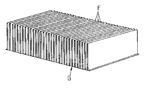
C&~h&~_~2~RIPTIO~ OF TH~ IMVENTION
Turning now to the drawings .wherein like reference
characters refer to like and corresponding parts throughout the
several views, the thickness of woven fabric structure G of the
invention is con rolled by the height of integrally formed
pleats F. The fabric structure comprises a first warp fabric
system or section I forming the base warp, and a second warp
fabric system or section II forming a plurality of generally
parallel pleatæ.
As more clearly seen in Figures 5-9, weft yarns 1 and 2
o first warp section I ~upport the pleats which are ~oined
thereto. The second warp fabric section II has pl*at wefts 3.
Wsft yarns 1 and 2 of ~ction I are interwoven by warp yarns 4,
and weft yarns 3 of the pleats of section II are interwoven by¦
warp yarns 5. Moreover, warp yarns 5 of second section II
$nterweave with waft yarns 1, 2 of first section I for
integrally ~oining the two sections together, as clearly shown
in Figure 6, 8 and 9. The height; of pl~ats F control the
thicknes~ of the woven fabric strucl:ure. Thus, ther~ are fewer¦
weft yarns 3 in each pleat depending on the height H desired.
The masimum pleat height is determined by the distance between
weav~ng reed 6 (Fig. 10) at the reed 5top and tpe fabric
take-off roll 7 of the wsaving machine, and can b~ more than
10cm. Thus, tha fabric take-off is in accordance with the
desir~d weft density. Each time after reaching the desired
weft numb~r (weft no. ~ weft density s pleat h~ight ~ 2),
controlled by the dobby card of the weaving machine, the stop
is efected. The basic warp threads 4 are shown in black
outline in the drawin~s and warp threads 5 oE the pleats are
I ,''~
.
- ... ~ :
:~ .
1 323285
shown by double lines. Both sections I and II have their own
warp beam rolls ~ and 9, respectively.
All the pleats F are joined at their free double ends to
the first warp fabric section as aforedescribed and estend from
the same side of the bas~c fabric section I. And, the pleats
are all the same height. In the Figures 3 and 9 embodiment,
the pleats lie perpendicular to plane E-E of Section I of
fabric G. Otherwise, the pleats can be interwoven such that
first section I lies at. an angle to plane E-E in overlapping
relationship in a shingle-like manner.
Depending on the desired pleat height, more or fewer
holding wefts 1 and 2 can be introduced. If, for example, a
dense upstanding attituds of the pleats is desired a~ in Figure
3, only one or two holding wefts 1, 2 are introduced. And the
weft6 can be~of thinner material compared to that of weft yarns
3. However, if a des~red angle i8 to be obtained for the
pleats F in the finished structure, such angle i5 controlled by
the height of the pleats in basa section I.
~ y using more than one pleat chain ~warp section II) it
i8 possible to produce alternating pleats from varying warp and
w~ft mater~al. Other mi~ed forms are also possible and can be
~elected according to the desired purpose. Thus, for e~ample,
it iS po88ibl~ to u~e varying weft material by means of weft
change~ ~n the individual pleats F, so that a suitable
structure can ~e produced.
In accordance with the present proeess, generally
illustrated in Fig. 10, the first warp fabric section I is
stored on warp b~am 8, and the second warp fabric section II is
stored on warp beam 9. The ~ections progress in a conventional
: ~ .
.
. : ,
1 323285
manner through beams 10 of the weaving machine. Weaving reed
6, via its reed stop (not shown), pushes the first hoiding weft
yarn 1, 2 of the new pattern repeat into the second holding
weft 1, 2 of the previaus pattern repeat and throws the fabric,
formed of the pleat warp and the pleat we~t, into a pleat.
Holding weft 2 also contrlbutes to the further holding of the
pleat. The weft take-off according to the weft density is in
the direction of arrow Z and in the direction of the arrow
as~ociated with roll 9.
At juncture 11 ~hown in Fig. 10, the interwoven first
and second sections are in a flat unpleated condition as'shown
in Fig. 50 Thus, first section I is woven as having
sub-lengths e~tending between weft yarn 2 (to the left in
Fig. 5) to weft yarn 1 (at the center in Fiq. 5), and from weft
yarn 2 ~at ~he center in Fig. 5) to weft yarn 1 (at the right
in this Figure). The corresponding sub-lengths of section II
are equal to the sub-lengths of saction I, as shown.
By means of an electron.ically controlled reversing
dev~ce (not shown) fabric take-off roll 7 is reversely rotated
by an amount equal to height H of the pleats to be formed.,
i.e., one-half the sub-length as aforedescribed. The pleats F
as shown in Figure~ 7 and 9 are thu5 formed as warp yarns 4 of
section I are ~hortened during the reverse movement of roll 7.
The thus loosened weave of section I is rolled back onto
its warp beam roll 8 by means of a suitabla motor (not shown)
in the direction of arrow Y. After again attaining the worlcin~
tension for the basic warp (section I) the weavlng machine is
automatically reinitiated.
The woven fabric according to the invention comprises
-8-
. - ;:
. ::
. :. .
' ~ `' ' .' : ' :,
'. .
.: ' ` .' ` ' :
~,, '.' ,
Il 1 323285
high-performance fibers, 6uch as glas~ fiber, aramide ~iber,
carbon flber, ceramic fibar, or a blend o such fibers, Fabric
~, interwoven as aforedescribed, is then impregnated with a
resin ~ystem to form a fabric structure having the desired
rigidity for the purpose intended.
Woven fabric strutura G is ~hown in Figure 1 as lining
an engine wall 13 which i~ e~sentially cylindrical although it
may be of othar desired shape~ as permitted by the elasticity
of the structura attained according to tha invention, The flow
of hot ga8e8 through linod cylinder 13 is shown in Figura 1 by
an arrow ~.
Obviou~ly, many other modifications and variations of
the pre~ent invantion are made possible in the light of the
above teachings. It i~ therefore to be understood that within
the scope of~the appended claim~ the invention may be practiced
otherwise than as specifically described.
_g_
.
~, `.' ~,