Note: Descriptions are shown in the official language in which they were submitted.
1 323400
ARC SPOT WELDING APPARATt1S
The present invention relates to an arc spot
welder for arc spot welding works by operating an
operation switch of a holder pressing a nozzle of a
welding torch onto the work.
The background of the invention will be described
with reference to Figures 14, 15, 16 and 17. For the sake
of convenience all of the figures will now be introduced
briefly as follows:
Fig. 1 is a perspective view of an arc spot
welder according to a first preferred embodiment of the
present invention,
Fig. 2 is a partially sectioned front view of the
welding torch of the arc spot welder shown in Fig. 1 or 5,
Fig. 3 is a partially sectioned front view of the
1~ no~zle of the welding torch showing a state of use,
Fig. 4 is a partially sectioned front view of the
nozzle of the welding torch showing a state thereof
immersed into a liquid to prevent sputters from adhering,
Fig. 5 is a perspective view of an arc spot
welder according to a second preferred embodiment of the
present invention,
' .
1`~' ~ :
.
. , : '
. .
- ` , ` , .
1 323400
Fig. 6 is a front view of the second wire feeder
shown in Fig. S,
Fig. 7 is a side view of the second wire feeder,
Fig. 8 is a side view of the second wire feeder
for showing a state of use,
Figs. 9(a) and 9(b) are sectional views of the
torch body assembly of the arc spot welder showing
variations of the present invention,
Fig. lO(a) is a front view of the weldlng torch
according to a variation of the present invention,
Fig. lO(b) is an end view of the welding torch
shown in Fig. lO(a),
Pig. 11(a) is a front view of the welding torch
according to another variation of the present invention,
Fig. ll(b) is an enlarged sectional~view of a~
portion of the torch body assembly~shown in F1g.~ a),
Fig. 12 is a front vlew of the~second wire feeder
according to a variation of~the second~preferred embodiment
of the present lnvention,
Fig. 13 is a side view oE the second wire feeder
shown in Fig. 12,
Figs. 14 and 15 are perspective views of
conventional arc spot welders, respectively,
:
Fig. 16 is a side view;~of the~se~cond wire feeder
shown in Flg. 15, and
2S
:
.
- , :: ~ :: : :
, ~
. . .: .
.,
.' , . ' ' . ' - '
. .
1 3233~00
Fig. 17 is an enlarged sectional view of the
tip end portion of the welding torch shown in Fig. 14
or 15.
Generally speaking, a target to be arc spot
welded has various shapes, e.g. narrow and complicated
shape, a vertical wall inside a box and the like. Arc
spot welding torches for aeneral use which are
commercially available are made small in shape in order
to meet various targets.
In the meanwhile, arc spot welding apparatuses
as shown in Fig. 14 are on the market for building
constructions, e.g. deck plates of electric cars or
architectural structures. The arc spot welding
apparatus is comprised oE a power source unit A to
supply electric power for welding, a wire feeder B for
feeding an electrode wire which is connected to the
power source unit A by a control cable D, and an arc
spot welding torch T' which is connected to the wire
feeder B by a torch cable F.
Arc spot welding apparatuses as shown in Fig.
lS are also on the market. This type of arc spot
welding
,
`, ' " ' " ' " ' ' .
', ': '
1 323400
apparatus further comprises one more wire feeder C to be
arranged near the welding torch T' which is connected to the
wire feeder s and the arc spot welding torch T' by an
intermediate cable E and a torch cable F, respectively.
This wire feeder C contributes to a rise in tha feeding p~er of
the electrode wire and, thereby, the working area can be
widened.
As shown in Fig. 17, the welding torch used in the
welding apparatus comprises a power supply element 4 to
1~ supply electric power to a welding electrode, a baffle
11 having small apertures 111 for spouting shield gas and a
nozzle 8' enclosing the welding electrode and the power
supply element 4 at the tip end thereof. Upon welding, the
nozzle 8' is abutted onto a target work and an arc is
lS generated by supplying - electric power between the welding
electrode and the target work via the power supply element
4. ~
In the meanwhile, upon arc spot welding, it is
necessary to make an upper metal plate stick to a lower
metal plate namely a base metal by pressing the upper metal
plate with the nozzle since the upper metal plate is stacked
on the base metal and is melted to weld.
As shown in Figs. 14 and 15, since both welding
torches T' used for the welding apparatus are relatlvely
small by the reason mentioned above, the operator has to
~5
bend ~- or kneel to operate the welding t Fch upon
: :
:
:
,~ .
..
.
,
` `
1 323~00
arc spot welding. Since the time necessary to arc spot
weld one spot is a few seconds at the most, such an
unstable posture as mentioned above may be considered to be
acceptable. But a relatively heavy quota is assigned to the
operator because of the brief welding time requir~d for one
spot. In the operation of the welding apparatus, the
operator walks to the next spot to be welded and
bends to perform the next arc spot weld, etc.
and, therefore, becomes very fatigued in order to finish his
quota assigned to him.
Further, it becomes difficult to press the upper
plate onto the base metal plate with reasonable force in
a bent posture, especially when the operator becomes
fatigued. This may invite dangerous weld defects which are
difficult to find in appearance after the welding.
In the welding operation to weld a deck plate
P, as shown in Figs. 15 and 16, the operator moves along a
groove of the deck plate P, namely in the X direction, to weld
individual spots while putting the wire feeder C of the
torch side in another groove. The wire feeder is moved
2~
along the groove by pulling the torch cable F. ~hen the
welding operation with respect to one groove is finishe~d,
the operator moves to the next groove to be welded in the Y
direction. If it becomes necessary to move the wire feeder
C for the next welding operation, the operator has to bring
it up by grasping the handle CH thereof in order to move it
' ',
` ' " ' . ' . ' '" ,
1 323400
to a suitable groove on the deck plate. However, the
operator is apt to pull the torch cable F in order to
-f~r~ibly move the wire feeder C. This invites the
wire feeder C to fall and/or a cut in the torch cable F.
On the other hand, so called sputters being molten
metal of several hundred degrees (C) are generated during
the arc spot welding operation and most of them adhere to
the inner surface of the nozzle N', as shown in Fig.17,
since it is pressed onto the upper plate. If the amount ~ t
adhered sputters increases, various inconveniences, e.g.
turbulence of the shield gas flow, electrical short circuit
bet~een the nozzle N' and the power supply element 4~may be
caused. In order to avoid these inconveniences, it becomes
necessary to remove adhered sputters during the
welding operation. However, removing the
adhered sputters is laborious because it has to be done
after detaching the nozzle N'. Further, it is impossible to
observe the state of adhesion of the sputter from the outside
and, thereby, an opportunity to remove the adhered
sputters i5 ap~ to ke lost. This causes various inconveniences
mentioned above. In order to decrease the adhesion amount
of sputters, there has been known a method wherein the tip
end portion of the welding torch is immersed beforehand into
a liquid for preventing sputters from adhering. However, if
this method is performed as it is, the Iiquid is prevented
from going inside of the nozzle N' by the air remaining in
:
: ` ~ - ,
' '
1 323400
the noz~le N' and, thereby, it is not ~;fficiently spread
inside the nozzle. Thus, it fails to prevent sputters
from adhering. If the no~zle N' and elements 4 and 11 of
the tip and of the welding torch ~' are immersed into the
liquid after detaching the nozzle from the welding torch, it
becomes possible to satisfactorily prevent sputters
from adhering but the immersing operation becomes laborious
since the nozzle has to be detached from the welding torch
at that time.
1 0
One oE objects of the present invention is to
provide an arc spot welder which is operable rom a
~standing position~
Another object of the present invention is to
provide an arc spot welder which is easy to move.
~ : ,
One more object of the present invention is to
provide an arc spot welder which is able~to e~ficiently
prevènt sputters~from ~dhering. ~ : ~
In order to accomplish these objects, according to
the present invention, there is provided
an arc spot welding apparatus comprising a weldi;ng :;:
power supplying unit, a wire feeder connected to the welding
power supplying unit by a control cable and an arc~spot
welding torch connected to the wire feeder by a torch cable
which is operable by operating an operation switch arranged~
on a holder thereof to be held by an operator being
,
1 323400
-- 8
characterized in that the welding torch comprises a nozzle
assembly providing a nozzle and a power supply element, a
torch holder assembly and a torch body assembly connecting
said nozzle assembly and said torch holder assembly which
is formed to have a length so that the operator can
operate said welding torch from a standing position.
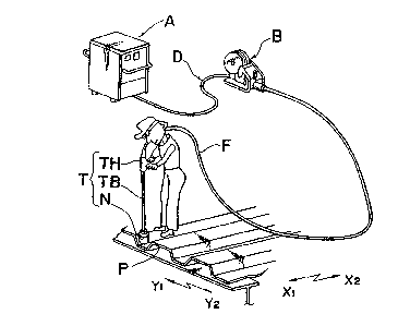
Fig. l shows an arc spot welder according to a
first preferred embodiment of the present invention.
The arc spot welder comprises a power source unit
A to supply electic power thereto, a wire feeder B to feed
an electrode wire and a welding torch T for arc spot
welding. The wire feeder B is connected to the power
source unit by a control cable D and the welding torch T
is connected to the wire feeder B by a torch cable F.
The welding torch T comprises a nozzle assembly N
to be abutted onto a workpiece P, a torch holder assembly
TH held by an operator and a torch body assembly TB
connecting the nozzle assembly N to the torch holder
assembly TH. The torch body assembly TB is formed to have
~n a length such that the operator can operate the welding
torch T from a standing position.
Fig. 2 shows the welding torch T.
The torch body assembly TB comprises an elongated
torch body l and an insulation tube 2 covering the elon-
gated torch body l from the outside thereo~. The elongated
:
.. ~ .
1 323400
~ - 8a -
torch body l has a hole lOl passing therethrough in the ax-
ial direction Zl thereof and male and female screws 102
and 103 are threaded on the inner and outer surfaces of
the free end portion of the torch body 1. The torch body 1
:
: '
::
1 323400
has a guide tube 3 to guide electrode wire which is
interchangeably fitted into the hole 101. This guide tube 3
is provided ~o prolong the life of the welding torch.
However, it may be omitted.
There are provided at the tip end side of the
welding torch a power supply element 4 fitted to the female
screw 103, an inner cylinder 5 made of an electrically
insulative material, e.g. ceramic which has a female screw
fitted to the male screw 102 of the torch body 1 and an
outer cylinder 6 supported by the tip end of the torch body
together with the inner cylinder 5. The inner and outer
cylinders 5 and 6 form an electrically insulative cylinder
7. A nozzle 8 made of a metal is detachably mounted on the
outer cylinder 6 of the insulative cylinder 7 for example by
` engaging a~screw of the nozzle 8 with a screw of the outer
cylinder 6. The insulative cylinder 7 is fastened by a nut
9 which is fitted to the male screw 102 of the torch body
1. A baffie 11 for a shield gas is fixed to the bottom wall
801 of the~nozzle 8 and the shield gas supplied into ~he
torch body 1 is spouted into the nozzle 8 through a gas
spouting hole 111 formed in the baffle 11. A small hole 802
is provided on the bottom wall 801 of the nozzle~ 8 in order~
to release the air in the nozzle~8 to the~abmosphere~which is
inclined to the axis of the weldlng torch. It~is desirable
to provide two or three holes 802 on the bottom wall 801 at
equal sngular pitch. The hole 802 ha~s~a dlameter oE 1 to 6
,:
`,
: .
- la -
1 323400
mms though it is dependent on the inner diameter of the
- nozzle ~ and, the quantity of supply of the shield gas. The
nozzle assembly N camprises elements from 4 to 11
mentioned above. The torch holder assembly TH provides a
holder 12 to be held by the operator, an operation switch 13
to be operated upon the ~elding operation and a holder body
1~ for supporting the torch cable F.
The length Lt of the welding torch T is designed
so as to be able to operate it from a standing position holding
the holder 12. Upon welding, the shield gas is supplied in
the nozzle 8 and electric power is supplied, via the
power supply element 4, to the electrode wire being fed by
the wire feeder B in order to generate an arc. In practice,
the length Lt of the welding torch T is desirably se~ at 650
mms t~hich is about three times the length of a ~
conventional arc spot welder. Thereby, the operator~can
operate the welding torch T from a standing posltion as ~hown
in Fig. 1.~ In other words, the operator can operate it
without the nee~ to bend and, theref ore, operator `
~atigue is minimized. Further, it becomes possible to
~ress the wcrk piece P with a reasonable force and, therefore,
a reasonably high quality arc spot~welding;results.
On the other hand, sputters generated in the arc
spot welding gradually adhere to the inner~surfa~ce of the
nozzle 8 and it becomes necessary to remove those sputters
adhered at an appropriate timing. According to a
: : :
1 ~23400
preferred embodiment of the present invention, the strong
- light of the arc generated in the arc spot welding can be
observed through small hole 802 provided on the bottom of
the nozzle 8. Since the arc light leaking out from the small
hole 802 decreases in the intensity thereof gradually as the
amount of adhesion of sputters increases, the operator can
deteLmine the amo~nt of adhered sputters from the amount of a light
leakage and thereby, it becomes possible to remove the
adhered sputters at an appropriate time. Further, since
the sputters adhered to the nozzle 8 and the baffle 11 are
easily peeled off, it becomes possible to remove the
sputters using a stick 16 inserted through the small hole
802, as shown in Fig. 3.
Moreover, the small hole 802 serves to release the
air in the nozzle 8 upon immersing the tip end of the
welding torch in the Ilquid ~to prevent~-- sputters from
adhering as shown in Fig. 4. Thus, the liquid is widely
spread on the whole of the inner surface of the~ti~p end of
the welding torch and, thereby, sputter adhesion is effectively
prevènted. Also, the immersing operation can
be done quite easily since it is unnecessary to detach the
~ 0 : :
nozzle fro~ the welding torch beforehand.
Next, a second preferred embodlment of the
present invention will be explalned with reference to Flgs.
to 8.
~s is apparentfrcm a c3mparison of Fig. 5 and Fig 1,
~ ~
:
~-~. : :
,
,
:,
:' ' .
- 12 -
1 323~00
the arc spot welding apparatus according to the second
preferred embodiment further comprises another wire feeder C
of a pull type to be arranged near the operator which is
connected to the main wire feeder B and the welding torch T
by an intermediate cable E and a torch cable F,
respectively. The welding torch T is the same as ~hat shown in
Fig. 2.
Accordingly, the second preferred embodiment is
characterized by the structure of the wire feeder C.
As shown in Figs. 6 and 7, the wire feeder C
comprises a guard member 25 having a wide bottom plate which
is detachably mounted thereto so as to cover the bottom
surface of the main body of the wire feeder C. The width W
and length Lf are determined so as to be larger than the
maximum width bl of the groove of the deck plate~P
(W > bl, Lf > bl). At respective ends in the width wise
direction of the bottom plate, rising portlons 251 and 251
are provided for mounting the bottom plate~to the maln body
of the wire feeder C and, also, two curved portions 252 and
252 are provided at respective ends ln the lengthwise ~
direction of the bottom plate in order to s~cothly guide the
wire feeder C onto the deck plate. The upper surEace of
the ~ire feeder C is covered by a cover plate 26 to render it water ~
proof which is hinged at oDe end in the lengthwise direction
of the wire feeder C and th~e other end of which is support~ed
by the guard member 25 free from opening and~closing. Thus,
.
: '
.
.
- 13 -
1 323400
the wire feeder C can be movedonto the deck plate P by
pulling the torch cable F. The width W of the guard element
25 is desirably set at a value of
[bl + (50 - 100)] mms. In this case, the wire feeder C may
drop in the groove of the deck plate P upon pulling it
around. However, the wire feeder C is merely inclined in
the groove because of the rising portion 251, as is
indicated by a phantom line in Fig. 8 and it is still
easily movable in a desirable directionby pulling the torch
cable F. The rising portions 252 can be omitted if the
length Lf of the bottom plate 25 is set nearly equal to the
length of the main body of the wire feeder. They can also
be omitted if the front and rear connector portions with
the cables E and F are formed 50 as to lessen the
inclination of the wire feeder C when dropped in the
1~ groove. Although the welding operation oE the deck plate is
usually performed outdoors, ~ the cover plate 26~can
protect the wire feeder ~ from rain or dust and, the
insertion of the electrode wire or the adjustment of wire
feeding can be easily madeby opening the cover plate 26.
This cover plate 26 can be made of a flexible material but is
desirabIy made oE a rigiù material in order~to protect the
wire feeder from an external force.
,:
If it becomes~ necessary to lift the wire feeder C
up or down to a higher position, a~handle CH as shown in
Fig. 15 can be mounted in place of the guard member 25.
:~
:
' ` ;;
'
. . .
1 323400
As is apparent from that rnentioned above, the wire
feeder C according to the second preferred embodiment can be
moved easily on the deck plate P with the aid of the guard
member 25. This enhances the efficiency of the welding
operation and serves to lessen the fatigue of the
operation. Since the length of the intermediate and torch
cables E and F can be set at several tens, for instance
thirty, meters and several, for instance eight, meters,
respectively, a reasonabl~ wide working area havi~g a radius of
about thirty eight meters in the above example, can be
guaranteed even if the main wire feeder B is fixedly set.
Figs. 9(a) and 9(b) show variations of the torch
body assembly TB shown in Fig. 2, respectively. In the
variation shown in Fig. 9(a), the torch body assembly TB `~
co~prises` a main body lof a torch, an insulation tube 2
covering the main b~dy 1 of a torch and a reinforcement 17
covering the insulation tube 2. In the variation shown in
Fig. 9(b), the torch body assembly TB comprises a main
body 1 of a~torc~ a reinforcement 17 arranged coaxially with
the main body 1 which has a radius larger than that of the
main body 1 and an insulation tube 2 which covers the
reinforcement 17. The reinforcement 17 can give a
reasonable mechanical strength to the main body 1 and,
thereby, the main body 1 can be madè to have a mLnimum
radius for electric power supply. Thus, even if the torch
body assembly TB is lengthened as shown in Fig. 1, the
,
1 323400
welding torch T can be made relatively light so as to be
able to easily handle the same.
Figs. lO(a) and lO(b) show a variation of the
welding torch shown in Fis. 2.
In this variation, a torch body 1 ~ of the torch )
comprises a first member Tsl and a second member TB2
and the first and second members TBl and Ts2 are connected
by a threaded rod so as to be adjustable in the axial
direction of the torch body assembly T~. The first and
second members TBl and TB2 are fixed to each other by
fastening a nut 20 after adjusting the distance
therebetween. The connection portion of the torch body
assembly is covered by a bellows 21 made of an elastic
material.
-Portions of the first and second members not
covered are covered by insulation members, respectively.
The welding torch T further comprises
reinforcement rods 17 and 17 extending parallel to the torch
body assembly each of which has a contact element 18 at a
free end thereof.
Each reinforcement rod 17 is bridged between a
support element l9a fixed to the holder assembly TH~and a
support element lgb mounted on the base of the nozzle
assembly N and is adjusted and fixed so as for the tip end
of the contact element 18 to position at the same level as
of the tip end of the nozzle assembly N.
:
;;
i : ~ ~ ' ;
.
'- ' ' '
.. .
- 16 -
- 1 323400
According to the welding torch T mentioned above,
it becomes possible to adjust the height thereof so as to
match the height of ~heoperator and the reinforcement
rods 17 and 17 with contact elements 18 and 18 contribute to
support the welding torch stably upon the welding
operation. Though it is also possible to provide one
reinforcement rod 17, it becomes necessary to avoid possible
interference between the tip end of the reinforcement rod 17
and the holder assembly TH. Further, it is also possible to
omit the portion of the reinforcement rod 17 defined between
the support elements l9a and l9b. In the case, the tip end
portions extending from the support element l9b should be
left as it is since they contribute to stabilize the postùre
of the welding torch T.
Figs. ll(a) and ll(b) show a variation of the
welding torch T shown in Fig. 2.
In this variation, the torch body asse~bly Ts is
comprised of first to third torch body element TBl to TB3
covered with an insulation tù~e which are successively
connected ~n the axial direction. Accordingly, the height
of the welding torch can be adjusted corresponding to the
.
height Of the operator by selecting~one among~the second ;~
torch body elements TB2 having various length~s-;~or~by ~ ;
connecting one more torch body element between the second
and third torch body elements TB~2 and TB3.
As shown In Pig. ll(b), the second torch body
:
.
:
:
- : :
~ ~ :
- . : ~ ' , '
.
'"' ' ~ ' .
- 1 323400
element TB2 comprises a rod element 201 having a
through hole and an insulation tube 202 covering the rod
element 201 except for one tip end portion to be inserted
into the third torch body element ~s3. At the other end of
the second torch body element TB2, there is provided an
insertion gap for accepting the tip end of the first torch
body element TB1.
As shown in Fig. ll(a), the insulation cylinder 7
comprises an inner cylinder 5 made of an insulative
material and an outer cylinder 6 made of a metal formed
integrally to the inner cylinder S and is detachably mounted
onto the torch body 1. The nozzle 8 is detachably mounted
onto the insulation cylinder 7. In this case, since the
baffle 11 is supported by the power supply element 4, only
the nozzle 8 can be dismounted irrespectively of the power
1 supply element 4. Further, it is desirable to perforate
small holes 802 at positions lower than the bottom wall 801
of the nozzle 8, in other words,;at positions between the
bottom wall 801 and the gas spouting hole 111 of the baffle
11 .
This structure er~bles the operator to observe the state
~0
of adhesion of sputters re clearly and is more ~convenient for : :
removing adhered sputters.
Figs. 12 and 13 show a variation of the wire
feeder C of the torch side as shown ln Figs. 6 and 7. In
this variation, handles CH are mounted on side walls of the
~ ~ :
~, .
. -
.
. . . . .
- 18 -
1 323400
main body of the wire feeder C thereof using screws in such
a manner that the guard member 25 can be dismounted from the
main body of the wire feeder C thereof without dismounting
them. A water proof cover (not shown) can also be provided
in this case.
Further, it is possible to contain the wire feeder
C of the torch side in a space formed between the guard
member 25 and the water proof cover.
It is understood that various other modifications
will be apparent to and can be readily made by those skilled
in the art without departing from the scope and spirit of
the present invention. Accordingly, it is not intended that
the scope of the claims appended hereto be limited to the
description as set forth herein, but rather that the claims
be construed as encompassing all the features of patentable~
novelty that reside in the present invention, includiny all
features that would be treated as equivalents thereof by
those skilled in the art to which the present invention
pertains.
: ~
::
': ; :
::
.
.