Note: Descriptions are shown in the official language in which they were submitted.
~ 3 ~
This inventlon relates to a devlce having a shutter wlndable
around a spindle and adapted inter alia to close a bay or other
openlng by the unwlnding of the shutter.
One of the main obJects of this Invention ls to provlde a device
of the klnd hereinbefore set out which ls of very slmple desl~n
and constructlon and hlghly reliable.
To this end, the shutter of th devlce according to the Inventlon
has flexlble slde edges which pro~ect beyond the shutter plane
and whlch are retalned wlth reduced frlctlon In substantlally
contlnuous ~uideways durlng the unwlndlng and wlndlng - I.e.,
wlndlng-on - of the shutter.
~dvantageously, the proJectlng edges are embodled by a serles of
small flexlbly interconnected substantlally rigid and
substantlally identical blocks so that the pro~ectlng edges can
wlnd splrally around the splndle.
Very advantageously, means are provided lnter alla at least at
the helght of the bottom part of the bay to enable the shutter
edRes to disenga~e from thelr guldeways when sub~ected to a
predetermlned pull transversely to guldeway length, notably
subst~ntlally In the shutter plsne.
~;3~
2 27806-2
In an embodlment of the lnventlon, each guldeway has ln
lts top part an access passage through whlch the pro~ectlng edge
of any shutter whlch has disengaged from the guldeway can re-
engage, as the shutter wlnds around lts splndle, in that part of
the partlcular guldeway concerned whlch ls dlsposed beyond the
passage.
The lnvention also relates to a device havlng a shutter
wlndable on a drum around a shaft and adapted inter alla to close
a bay or other openlng by unwlndlng of the shutter.
Accordlng to the lnventlon, the latter devlce comprlses
a wheel ~igldly secured to one of the free ends of the shaft, the
same extending laterally beyond the drum, wheel dlameter being
less than drum dlameter, a counterwelght so co-operatlng wlth the
wheel as to rlse when the shutter unwlnds and to descend when the
shutter wlnds on to the drum, damplng means belng provided to
retard shutter movement a llttle before the shutter reaches its
fully wound and fully unwound posltlons.
Accordlngly, ln a broad aspect, the lnventlon resldes ln
~ devlce havlng a shutter wlndable around a splndle and adapted to
close a bay or other openlng by the unwlndlng of the shutter, the
shutter comprislng flexlble thlckened slde edges whlch comprlse a
successlon of small closely-spaced flexlbly-lnterconnected
substantlally rlgld and substantlally identlcal blocks whlch
pro~ect beyond the shutter plane and extend in the prolongatlon of
: each other, ln substantlally the same way as the me~hes of a sllde
fastener and whlch are retalned wlth reduced frlctlon ln
substantlally continuous guldeways durlng the unwlndlng and
wlndlng-on of the shutter, means belng provlded at least at the
2a 27~06-2
helght of the bottom part of the bay to enable the shutter edges
to dlsengage from thelr guldeways when a predetermlned pulllng
power transversely to the longltudlnal dlrectlon of the guldeways
ls applied to these edges, each guldeway havlng near and upstream
of the shutter splndle of the shutter an access passage through
whlch the correspondlng pro~ecting edge of any shutter, whlch has
dlsengaged from the guldeway, can re-engage ln that part of the
partlcular guldeway concerned whlch ls dlsposed beyond the access
passage durlng the wlndlng-on around the splndle and the
subse~uent unwindlng of the shutter sald means comprlslng guldlng
members whlch can be opened under sald pulllng power.
Further details and features of the lnventlon wlll
become apparent from the following exemplary and non-llmltatlve
descrlption of an embodiment of the inventlon, reference belng
made to the accompanying drawings wherein:
L ~7 fJ '~ e.v 7 i'
Flg. I is an overall diagrammatlc view in front elevation, with
psrts broken away, of the embodiment;
Flg. 2 ls a view ln slde elevation of the same embodiment, to an
enlarged scale;
Flg. 3 ls a sectlon on the llne III-III of Flg. 1 to an enlarged
scale and with parts broken away;
.
Flg. 4 is a vlew to an enlarged scale, ln front elevatlon and
wlth parts broken away, of a detail of the top part of Flg. 1
wlth part of the shutter edge dlsengaged from Its guideway;
Flg. 5 Is a slde vlew wlth parts broken away of the same detall
as shown In Flg. 4 except that the shutter has been omltted for
the sake nf clarlty;
Fi~. 6 ls a sectlon to an enlar~ed scale on the llne Vl-VI of
Fl~. l;
FiX. 7 i5 a section, also to an enlar~ed scale, on the llne Vll~
Vll of Flg. 4, and
Fig. 8 ls a sectlon si~ilar to Fig. 6 except that the shutter
edge is psrtly disengaged from lts guSdeway~
~ .3 2 ~ ~
Llke references denote like elements throughout the drawing.
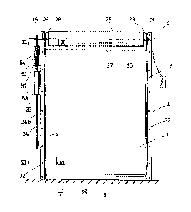
The devlce according to the Invention, an embodiment of which is
shown in the accompanying drawings, comprises a shutter 1 adapted
to be wound - i.e., wound on - around a splndle 2 and adapted to
close a bay 3 or any opening or passage by unwinding of the
shutter.
The word "shutter" is to be understood for the purposes of the
Invention as referrin~ to any element adapted to be wound - l.e.,
wound-on - around a spindle, such as a tarpaulin, set of plvoted
slats or the llke.
However, there ls a deflnite preference for flexible shutters ln
the for~, for example, of a tarpaulln.
The descrlptlon given herelnafter has therefore been llmlted to a
correspondlng embodlment of the Inventlon.
In general the devlce accordlng to the Inventlon Is dlstlngulshed
In that the shutter 1 has flexible slde edges havlng a part 4
whlch proJects beyond the shutter plane and which is retained
with reduced frictlon ln substantlally continuous ~uldeways 5 so
as to be ~ovable thereln when the shutter 1 unwinds and wlnds.
~ ~Y2'~
- 5
Advant~eous1y the part 4 ls In the form of a series of small
flexlbly lnterconnected identlcal rigid blocks 6 enabling the
shutter side ed~es to wlnd ln a splral around the splndle 2.
The blocks 6 can be ~ade of a rlgld plastics moulded on a f~brlc
strip 1' which Is secured to the tarpaulln edKe and of which, for
example, the shutter is made, at a distance apart from one
another such that any two consecutlve blocks csn pivot relatively
to one another and thus wind the shutter side edxes around the
splndle 2.
In prsctlce lt ls preferred to have blocks 6 for~ed by what are
~nown as "the neshes" of a conventlonal sllde fastener.
The pro~ectlng part 4 of the shutter slde edges can therefore be
embodled by one of the two lines of such a slide fastener. Thls
is one of the features clearly shown in Flg. 4.
Each guldeway 5 has two longltudlnal edglngs 7, 8 whlch extend on
elther slde of the shutter side edges, more partlcularly of the
p~rt 4. The ed~lngs 7, 8 face one another so as to en~sge to
some extent around the part 4 whlch Is ret~lned In the Kuldeway
5.
~ ~j 2 !-; &) ~
-- 6 --
In the embodiment illustrated each guldeway 5 comprises two
separate sectlon members 9, 10 whlch extend some distance in
slde-by-slde relationshlp to one another while belng retatned by
way of thelr base 11 ln a support 12.
A part 13 of the members 9, 10 extends beyond the support 12 and
has the longitudinal edgings 7, 8.
More particularly, the two sectlo~ members 9, 10 ha~e a
substantlally Z-shaped cross-sectlon, one of the arms forming the
edgin~ 7, 8, while the other forms the base 11. The support 12
take~ the form of a channel-sectio~ member whose arms have facing
edgln~s 14, 15 resembling the shape of a C. The two Z-sectlon
~emberQ 9, 10 are retalned by three lntermedlate members 16 - 18
clamped between the support 12 and the members 9 and 10 and also
between the members 9 and 10. The helght of the ed~lngs part 13
whlch extends beyond the support 12 can be ed~usted by alterln~
the thicknesses of the members 16, 17.
lo this end, it may be lmportsnt for the gap ~ between the base
of the channel-sectlon member 12 and the edgings 14, 15 thereof
to be greater than the thlckness of the arms 11 of the members 9,
10.
~ 3 2 ~ ~7 ~
Advantageously, the two members 9, 10 are ~ade of plastlcs,
preferably B self-lubrlcatlng plastlcs, whereas the support 12
is, wlth advantage, a metal sectlo~ member.
Also, the part 13 has some resillence so that the blocks 6 on the
shutter side edges can dlsengage from thelr guideway 5 ln
response to a crltlcal pull athwart the length of the blocks 6,
Inter alla substantlally ln the shutter plane. Thls feature is
shown clearly ln Flg. 8, in whlch the dlrectlon of the pull is
lndlcated by an arrow 19.
Hlgh rellablllty Is therefore ensured, ensurlng that the device
cannot be damnged ln very severe storms and ln partlcular when
the sh~tter Is knocked by a vehlcle when, for example, In lts
closed or partly closed posltlon.
The support 12 is recelved freely ln a channel 37 sub~ntially
axlally thereof. The channel 37 ls embodled by another channel-
sectlon member 40 stlffer and wldcr than that of the support 12
and secllred by screws (not shown) or by weldlng to 8 frame 32
nrranged on the ed~es of the bay 3 (see Fl~s. 2 and 6 - 8), a gap
38 belng left on elther side of the support 12 between slde wall
41 thereof and Its arm dlsposed opposlte the wall.
~L ? 2
-- 8 --
A clamping element 36, in the form of a cylindrical metal tube ln
the present case, extends alon~ the support 12 and bears, with a
force adJustable at least laterally, on the support 12 so that
the distance between the edges 14 and 15 and, therefore, the
~ strength of the pull necessary to disen~age the shutter ed~es 4
from the guideway 5 can be adJusted.
More psrtlcularly, the tube operatlve as clamping element 36 is
en~aged laterally and to some extent to some depth In the gap 48
and is secured by screws 39 which extend right throu~h the tube
to the base 42 of the channel 37. The outslde dismeter of the
tube 36 ls greater than the distance between an arm of the
support 12 and the channel slde wall 41 disposed opposite such
arm so that when the screws 39 are tlghtened the support 12
experiences a force having one component dlrected towards the
channel base 42 ~nd another component operative ln a directlon .
parallel to the base 42 and towards the latter arm.
In thls connectlon the screws 39 are secured ad~ustably tn tapped
apertures 43 ln the channel b~se ~2.
,, .
Consequently, by means of the two tubes 36 disposed on elther
side of the support 12 the same can be secured releasably and
ad~ustably to the channel-sectloq me~ber 40 and the distance
between the free ends of the ed~ings 14, 15 and the support 12
`-
~ ~ 2 ~ ~7 .L. i_~
- 9 -
-
and, therefore, the gap and, possibly, the pressure between the
me~bers 9, 10 and the pro~ectlng shutter edges 4 can be adJusted
by tlghtening or slackenlng the screws 39.
As Figs. 4 and 5 show ln detall, each af the guldeways 5 hus in
accordance wlth the inventlon ln lts tap part an access passa~e
20 through whlch any blocks 6 whlch have disenga~ed from thelr
guldeway 5 can re-engage automatlcally ln that part 21 thereof
whlch ls dlsposed lmmediately above the passage 20 when the
shutter l rlses, as indicated by an arrow 22 ln Flg. 4 - l.e.,
when the wlnding around lts splndle 2.
In the embodlment lllustrated the access passage 20 ls produced
by cuttlng out over a dlstance of a few centlmetres that part 13
of the members 9, 10 which extends beyond the suppart 12. It
might sometlmes sufflce to cut ~ust the edgings 7, 8 of the
me~bers 9, 10 to enable the shutter edges 4 to re-engage between
the ~embers 9 and lO.
Accord1ng to another fe~ture of the invention, to provide some
guldance of the blucks 6 axially of the guideway 5 at the entry
of the passage 20, the edgings 7, 8 whlch bound the bottom slde
of the passage 20 are formed wlth a V-shaped cut-out 23.
! 7
-- 10 --
In the guidewsy part 21 the part 13 of the members 9, 10 is
stren~thened on its outside surfaces ~y stlffeners 24 whlch
prevent the small blocks 6 from dlsengaglng from the members 9,
10 In response to a pull ln the directlon lndicated by the arrow
19. This feature is illustrated by Fl~. 7.
The polnt ls that in the absence of the stlffeners 24 the ~embers
9, 10 mlght posslbly open a llttle as shown ln Flg. 8 in the
region where the blocks 6 enter the guldeway part 21 upon re-
engagement ln the ~uideway.
ln this connectloq, since the part 21 is disposed In the top part
of the bay 3, the rlsks of any such force ln the dlrectio~ of the
arrow 19 occurring in this zone are very sli~ht.
Preferably, the drum 1 winds on to a drun 25 which Is of fairly
large dia~eter and, therefore, relatlvely rlgid and whlch is
rotatable around the spindle 2 in the top part of the bay 3.
The top free end of the two guldeways 5 extends almost as fsr as
the cyllndricsl drum wall so as to ensure satlsfactory winding of
the shutter on the druo.
Advanta~eously, a relatIvely thin strlp 26 of the shutter 1 is
secured by way of its top ed~e, for example, by stlc~lng or
rlvetlng, to the cyllndrical dru~ wall along the generatrix of
~L~ ;9"' 1~
the drum, lts bottom edge belng releasably connected to th~
re~alnder of the shutter, for example, by a slide f~stener 27.
Thls may be very practicable for the installation of the devlce
or for the replacement of the shutter.
The shutter slde ed~es pro~ect beyond both ends of the drum 2
when the shutter wlnds on to the drum 25. This Is shown in
detall in Fi~. 3.
A gap 28 is therefore left at elther end of the drum 25 ln
extenslon thereof.
The lon~ltudlnal axis of the guideways extends approximately in a
vertical plane tangentlal to the cyllndricall wall of the drum on
that slde thereof on which the wlndlng of the shutter 1 starts,
so that according as the shutter side edges disengage fro~ the
top end of thelr respectlve guideway they can, as the shutter I
wlnds on to the drum 25, wind freely around the splndle 2 and
drop back Into the gap 28. This featur-e helps to compensate for
the excess Lhlckness of the slde ed~es of the wound shutter.
:`
The shutter therefore remains properly stretched on the drum and
the shutter surface needs no oYerthlcknesses to compensate for
the thickness dl~ference between the blocks 6 and the shutter 1.
~. :3 .~?J'~
-- 12
The ~uldeway axis can In fact be dlsposed in a vertical plane
tan~entlal to the cyllnder formed by half of the wound part of
the shutter on the drum.
If the shutter i5 in the form of a tarpaulln of relatively
reduced thlckness, varlatlons In the diameter of the shutter
wound on the drum are also very reduced, more particularly slnce
drum dtameter Itself may be relatlvely substantial.
Shutter-drlvln~ means are provlded so that at least for windln~
the shutter I on the drum 25; preferably, the shutter bDttom ed~e
ls welghted unlfor~ly over lts len~th to permit or facllltate
unwlndin~ of the shutter, basically by lts own wel~ht.
In the embodlment shown the shutter-drlvlng means comprlse a
motor (not shown) incorporated in the drum 25.
Advantageously, the drum 25 Is in the form of a hollow cyllnder
made of a hard plastlcs such as polyvlnylchlorlde and ls
therefore very rlgld but relatlvely ll~ht tn welKht. The drum
25 Is rotatably mounted on 8 shaft 29. The free ends thereof
which extend beyond the drum 25 are disposed In the frame 32
formed by L-sectlo~ me~bers whlch bound the bay 3 laterally and
on whlch, as prevlnusly stated, the channel-sectlon me~bers 40 Df
the guideways 5 are secured.
~L ~3 2 ~ ~
- 13-
The shutter-drivin~ means, more particularly the drum-dri~lng
means, also comprlse a counterweight 33 suspendf~d by a chain 34
on a sprocket 35 rigidly secured to one of the free ends of the
shutter 29.
The chaln 34 ls open and ls so placed on the sprocket 35 as to be
ln the form of two runs 34a, 34b han~lng freely on elther slde of
the sprocket 35.
The counterweight 33 is suspended on the chain run 34a so as to
rlse when the shutter 1 unwinds and to descend when the shutter 1
winds on around the drum 25.
Da~ping means are provlded to damp the movement of the shutter 1
a llttle before it reaches Its fully wound and fully unwound
posltlons. To thls end, in the embodiment illustrated, more
particularly in Fi~. 2, the dampln~ means comprlse at each end of
travel of the chain 34 near the pinion 35 two alr dampers 53 - 56
e~tendlng ln palrs on either side of the chain runs 34a, 34b.
Each damper has a plston rod 57 whlch moves ln a cylinder and
whlch extends through the cyllnder base parallel to the chaln
runs.
Entralnlng elements 58, 59 are provlded on each of the chaln
runs 34n, 34b for actlvatlng the plston rods 57 when the runs
3 2 ~ ~ ! ~
- 14-
rlse, thus produclng gradual damplng or retardatlon of the
movement of the shutter 1.
~Iso, the plston rods 57 actuated by the elements 58, 59 can
actlvate swltches 60, 61 dlsposed in the motor supply clrcuit and
arranged alon~ the path of the runs 34a, 34b respectIvely so as
to swltch off the motor when the dampers are providln~
retardation.
It has been found convenient in pract~ce to switch off the motor
substantially at the start of retardation of the shutter.
It would of course be possible to use separate elements actln~ on
the swltches.
In the embodlment shown the weixhted ed~e Is embodled by a steel
bor disposed in a recess 50 on the bottom ed~e of the shutter l.
The recess 50 can also receive below the steel bnr a flexible
cushion 51, for exampIe, of foam, to p;ovlde sealing tlghteness
between the shutter l and the ground 52 boundln~ the bottom side
of the base 3 when the shutter I is ln its fully unwound position
as shown ln F16s. 1 and 2.
Finally, to provlde sealln~-ti~htness in the top part of the bay
3 when the shutter l is in Its closed position a bead 30 is
-
- 15-
engaged over substantially the whole width of the shutter outside
surface sll6htly above the level of the lintei 62 bounding the
top slde of the bay 3 when the shutter is completely unwound (see
Fig. 2~.
The lnventlon is not of course llmlted to the embodiment
descrlbed and shown in the accompanylng drawlngs and can be
varled ln many ways wlthout departure from the scope of the
InventLon.
For example, the small blocks 6 could be replaced, for example,
by a contlnuous flexlble bead posslbly in the form of a cord
secured along the whole length of the shutter side ed6es, whlle
the guldeway 5 could be a channel-sectlon member with edges bent
towards one another, the pro~ectlng part 4 of the shutter slde
edges slldlng, for example, directly in the guideway 5.
The drumrdrlvlng means could take the form of a motor and
transmlsslon dlsposed outslde the drum or of a spiral sprlnx
dlsposed in the drum and actlng on the shaft 29, the spring belng
cocked when the shutter unwlnds and thus facilitating or
Inltlatin~ the wlndlng of the shutter, or Just by a
counterweight.
.
- 16-
The shutter device could also be used nut only to close window or
dDor bays but, for example, also as as retr~ctable partltlon in a
room or to cover swimming pools and to close silos or tanks.