Note: Descriptions are shown in the official language in which they were submitted.
1324414
62196-514
EL~CTROSTATIC DEEP H~ATING APPLICATORS
Field of t~e Invention
The present inventlon relates generally to hyperthermia
treat~ent of tu~ors and specifically to the selective and unifor~
deposit~ng of RF energy during such treatment
Bac~oround of t~e Invention
Heating of cancerous tu~ors is now recognized as a
valuable ad~unct to the long established ~reat~ent with
c~emot~erapy or radiot~erapy because the treatment effectivity is
often enhanced when hyperther~ia is lncluded as part of the
protocol It ls thus desira~le to elevate t~e tumor temperature
as ~uc~ a~ pos~ible ~ithout causing in~ury to healt~y tissue
during the hyperthermia treatment ~ `~
Effective heating of a tu~or deep withln the body ~ay at
8 to 10 c~ depth, ~as been a goal of many appllcator deslgners
Thi~ l~ very dlfficult to ac~leve, however, and i~ always limited
by the allo~able temperature elevatlon of healthy tissue at lesser `~
depth~ a~ well a~ at the muscle-fat interface or at the surface
lt~
A prlor art hyperthermla ~ystem used to heat tumors in
t~e tor~o of the body co~prlse~ an RF power ~ource coupled via a
~atchlng networ~ and a tran~mi~sion llne to an appllcator, and
then to the tor~o of the patlont The RF power sourco typlcally
would provlde ~00 to ~000 watts ~hermometry egulp~ent ls
connected to the patlent to monltor temperature at various
locatlon- via fiber-optlc probes Thls thermal infor~atlon can
.,', . ':
~` ~ .. ,:
~ ... ~.
1 32 4 ~ i 4 62196-514
also be used to control the amplitude of the RF power source
throug~ a feed back loop if desired.
Various applicators have been successfully devlsed to
heat tumors. However, heating has ~ost cons~stently been ac~eved
in surface or near surface tu~or t~erapy w~ere the overlying
tissue ~s not a basic llmitation. The desi~n of applicators for
thi~ type of therapy are relatively straightforward and often
operate at ~icrouave frequen~ies where some focuslng can be
achie~ed. Other applicators that are ~ore specifically designed
for deep heating have also bean developed. These devices
qenerally operate ln the lower HF or VHF frequencies where greater
depth of penetratlon is possible. Several relevant devices of
thls type are d~cussed in the literature.
They are~
1. ~Deep Heating Electrode~, Harri~on, U.S. Patent No.
~,325,~61, Aprll 20, 1982:
2. ~Focused Blectrouagnetlc Heatlng of Nuscle Tissue~ EE
tran~. NTT-32, ~8, August, 198~, pages 887-888~
3. ~Annular Phased Array~, IEEE Tran~. BME-31, pages 1-6-
106~ , January, 198~
~. ~A T~ree-Dluenslonal Model For The Coaxlal TEH Deep-Body
Nypertheruia Applicator,~ Int.J.Hyperther~ia, 1986, Vol. 2, No. 3,
pages 2-3-252~ and
5. ~A Ne~ Coaxlal TBN Radlofreguency/Mlcrowave Applicator
For Non-Invasive Deep-Body Hyperther~ia, ~ Journal of Hicrowave
Po~or, 1983, 18, pages 367-375.
; :,''"
. .
: .
132~
62196-51~
6. "Capacitor Electrodes for Shortwave Dlather~y", Hyperther~la
in Cancer Therapy, G.K. Hall Medical Publisbers, pp 284-287 . ;
7. "co~parison o$ Deep-Heating Electrode Concepts for
Hyperthermia~, J. Nicrowave Power 1985, pp 1-8.
8. ~Resonant Ridged Naveguide Structure Operating at 27HHz. n
U.S. Patent ~4,282,887.
These devices are capable of penetratinq the
subcutaneous layers and heatlng imbedded tu~or tissue without
serlous surface overheating. However, each has lts limltations. `
1. The patent entitled ~Deep Heating Electrode, n U~ S
Patent No. ~,186,729, conslsts of a single turn, resonant, non-
contactlng cylinder that surrounds the body and does not reguire
bolus ~ater baqs~ bet~een the electrode and the patient. The
conducting ~heet for~s the inductor and the overlapplng sheets
for~ the capacltor requlred to resonate the clrcuit. The devlce
typlcally operates on the lo~er ISH frequencles, l.e., 13.56,
2~.12 or ~0.68 NHz. N~en ~ed fron an RF power ~ource, the
re~ulting lnduced concentrlc electrlc field llne~ are parallel to
the body ~urface and energy depo~ition ln the deep ~uscle tlssue
ls not dependent upon electrlc field line~ that ~u~t pass through
the fat~ln layer. Clinlcal experlence ~lth over lOOO patients
~bo~s that exce~lve ~urface heatlng l~ ~pared and deep heatlng ls
often achleved.
Ho~over, tbe concentrlc electric field strength is
. .
proportlonal to the radiu~, thus heatlng is al~o dependent upon
the relatlve radlal locatlon. Calculatlons and experience have
''.~', '`' '
' .
1324414
62196-514
shown that the half-power depth of penetratlon ls typloally 6 to 7
cm below the surface of the torso with a patlent havlng a 1 to 2
c~ fat layer.
2. T~e paper ~Focused ElectroDagnetic Heating of Muscle Tlssue
HTT-32~ describes an applicator that conslsts of two identical
~etallic cylinders spaced from one another and placed
concentrically over a cylindrical phantom s~mulatin~ muscle tigsue
to be heated~ A very thin 2 ~ insulator i5 placed between the
phanton and the netallic cyllnders. The cylinder diameterr
phanton dl~ensions and frequency of operation are chosen to obtain
constructive lnterference ln the central region of the
l~mb~phantom to be heated. For the case cited in this paper thls
approao~ requlre~ an RF po~er source operating at a freguency of
150 NHz.
The concept 18 acceptable when worklng wlth an
e~perlmental unlfor~ cyllndrlcal phanto~. However the approach
has seriou~ itatlons ~ben dealing ~lth the shape irregularities
of a bu~an torso ~here tbe requlred mlnlmum ~paclng to the body
cannot be ~alntalned and tnls compro-l~es the necessary radlal
pha~e relatlon~blp~ As dlscussed thereln a lO cu dia~eter
pbanto- ~as u~ed ~ith ~ust 2 ~ ~paclng between the phantom and
the oyllndrical netallio shells l.e. a very preclse spaclng not
aohle~able ln a cllnlcal envlronment.
3. Tbe de~lce ln the paper ~Annular Phased Array " conslst~
of a group of as many as 16 dlpole element~ that are radlally
spaoed around the patlent ~ tor~o and fed ln phase from a common
.:
:,,
132~14
62196-514
RF source. To obtain sufficlent RF coupllng to the body, .
distilled water bags are placed between the dipoles and the
patient. This allows the dipole elements to function in a medium
having a dielectric constant similar to muscle tissue
(approximately 78), thus enhancing the coupllng and mlnlmlzing the
discontinuity between the dipole eleDents and the body surface~
By carefully filling all the voids between
' ~"
'' .
'.:' '"'
. '''
~a
''.
132~ 66-49
the dipole elements and the patient with water bags,
efficient RF energy transfer and heating can be achieved
at depth
From a human usaga point of view, this device also
has serious limitations It is very difficult to
achieve uni~orm filling of the voids around the patient
with wa~er bags Variable fat thickness, with its lower
dielectric constant, also creates additional
discontinuities When these variations occur, localized
lo hot spots will exist that can cause injury or limit the
extent of energy input possible without localized
thermal damage It is also very time consuming to
propQrly position the watQr bags and check for localized
heating beforQ treatment begins, thus contribu~ing to
patient fatigue and degraded treatment tolerancQ
4 The dQvice disclosed in the paper ~A Three-
Dimensional Model For The Coaxial ~EM Deep-Body
Hyparthermia Applicator~ develops a very detailed three
dimansional mathematical model showing that deep heating
is possibl- using a pair of cylindrical ~leeve-~ as
described abovo This rainrorces the theoretical
reasons ~hy th pr s nt invention functions wall It
concludes, ~For an rficient electromagnQtic coupling, a
suffici ntly cooled watar bolus batween the apertur~ and
the hu~an body is necessary~
T~ device diQclosed in tha paper ~A New
Coaxial TEH Radiofrequency/Microwave Applicator For Non-
Inva-iv- De-p-Body Hyperthermia~ provides a limited
th or tical evaluation of the same model showing that
tho applicator will work with human body di~ensions and
verifio~ th-se pr~dictions with a small model operating
at an appropriately scaled higher frsquency It also
requir s th- use o~ a wat~r bolus The paper concludes,
~To ~atch the patient to the applicator aperture, a
3S distilled water bolus between the patient and the
applicator aperture is necessary~
-5-
"'. '."''.:. ~
. :',, .
"
1324~14
62196-514
6. The device described in the paper "Capacltor Electrode~
for Shortwave Diathermy,~ illustrates the serious theoretical and
practical limitations of employing either contacting or
noncontacting plates when heating a phantom (skin/fat and muscle)
with RF energy. The resulting E-field llnes and current flow are
perpendicular to the body surface. Thus the current path is ln
series with the fat and ~uscle resulting ln t~e hlgher res1stance
fat belng seriously over heated.
T~is article further descrlbes where two small plates ::
lin ter~s of body size) are placed on the sa~e surface of the
patient. They produce currents flowlng between the~ and t~rough
t~e fat and ~uscle tissue. ~ut also a large perpendicular current "`
flo~ passes t~roug~ the fat causlng surface overheating. This
reference and discu~sion is included to clearly distlnguish thls -~
approach froa t~at of t~e present lnventlon. T~e present
lnvontlon, to be doscrlbed, e~ploys large plates, ln terDs of body
~lze and t~ey forn a resonant aperture by which longitudlnal E-
fleld energy ls transferred.
7~ Tho artlclo ~onparl~on of Deep Heatlng Electrode
Concopts for Hypert~ernia~ further discus~es the u~e of oppo~ing
plates and thelr linitations and also provldes depth of
pen~tratlon details for various applicators.
. ~ " .
8. U.S. Patent ~,282,8a7 entitled "Resonant Ridged
~aveguldo Structure Operatlng at 27 NHz.~ describes a rldge
waveguide structure t~at is fllled witb water to lncrease lts
, ~ .
1324414
62196-51g
effective dimensions to make it resonant at 27MHz and yet small
enough to fit on the body. A rubber bag, filled wlth delonized
water, fits over the waveguide opening. A second rubber bag ls
placed over top of the first. It is filled with a saline
6a ;
A ;
. . .... :
~ 56
absorption solution to prevent over heating of the
fringe area around the periphery This second bag hac
its center removed so that the third water cooled bag
A ~ employing circulating water, is placed in the void
s and used to cool the fat layer that is excessively
heated Energy is coupled into the body im~ via these
multiple water bags Power to the device is applied to
the applicator wit~ a coax to waveguide transition l3~
The various prior art devices described above have
the limitation of being close fitting around the object
heated or using a water bolus to fill the void between
the applicator and ob;ect to be heated The IJH paper
concludes, ~For an efficient electromagnetic coupling, a
sufficiently cooled water bolus between the aperture and
the human body is necessary ~ The JMP paper concludes,
~To matc~ ths patient to the applicator aperture, a
distilled water bolus between the patient and the
applicator aperture is necessary ~
Prior art devices 2 through 5 are not resonant
devic-s and a sorious impedance mismatch with the 50 ohm
lino to th- RF pow r sourc- will result unless a water
bolus is us d as described~ Moreover, the lack of a
resonant structur limits the frequencies which may be
employed in the d~vices
Additionally, in a clinical environment, it is
pr fer~bl~ t~ us- as simplified a device a~ possible and
preferably ~ d~vice that does not surround the patient
Accordingly, it is the principal ob~ect of the
pres nt inv ntion to deposit RF energy in a uniform
manncr in tissuo
It is anoth-r ob~ect of the present invention to
tr-at tu~ors by hyperthermia treat~ent without the need
for a water bolus or an applicator closely fitting
around the patient
''' ''. ~'`
66-~9
132~
Yet another object of the invantion is to allow an
applicator to function at vario~s frequencies and to
optimally couple the RF energy to the applicator
A further object of the invention is to employ
structures that do not surround the patient, to
eliminate the need for side coupling elements and shield
plates
sum~ary of the Invention
T~e present invention, in a broad aspect, includes
lo a pair of identical metallic cylindrical or rectangular
applicator sleeves spacQd along the torso The
applicator sleeves are resonated with inductors
The sleeves ar~ wQll spaced from the body (radial
spacing) and ~o not require the USQ of a water bolus
between the applicator and thQ patient This is
possible because thQ sleeves becom~ part of the resonant
circuit employed to raise thQ imp~dance of the
applicator and obtain the necessary coupling to the
torso without a water bolus betweQn the patient and
applicator The r~onant circuit also becomes a part of
th~ matching circuit that precisely matchQs the cylinder
imp~dance to the 50 ohm RF power sourcQ To work on
differ nt fr~qu ncies, it is simply necessary for the
presQnt devic- to be re-resonatQd at the new desired
fr gu ncy by changing th~ I/C values in the circuit
Tho measured thermal r~Qpon-Qe of the present
inv ntion ~bows relativ-ly uniform heating at depth in
cro~s-s~ction~ equivalent to that of the human torso
In an alternat~ e~bodiment the preQent invention
consists o~ two, three or four larg- metallic plates,
that aro position~d in a non-contacting manor above and
b~low the tor_o, i ~, typically spaced 3 inches from
the patient RF i~ connectQd to the plates so as to
produce a longitudinal E-field within the body They are
made part of a resonant circuit with the addition of
--8--
-` ~32~414 -
62196-514
inductors. A water bolus between the plates and the patient is
not required.
While t~e power distribution is less uniform, the use of
just two plates is also very attractive because of its performance
characteristics, convenience and extreme simplicity. (The plates
can be placed in the table under the patient~ The E-field
mapping and phantom experiments show that remarkably good depth of
penetration is achieved while applying power from the one surface.
Tbis configuration can be beneficial in some cases where it is
desirable to li~it t~e overall heating to a more specific reg~on~
It also completely eliminates any patient constraint incurred by
positioning of surrounding applicator hardware~ -
~ dditional inductive and capacitive loadlng can be
e~ployed to eli~inate any E-fleld asymmetry or resonance
sensitivity~ It can also be used to purposely create an asymmetry
if an E-field concentratlon at a specific location is desired~
A beneficial ~ethod of providing unlform heatlng ls also
pro~ided ~it~ the invention~
Accordlng to a broad aspect of the invention there is
provided an electrostatlc deep heating applicator for tissue
conprising-
sleeve ~eans, axlally spaced and disposed in a non-contacting
relatlonship around said tlssue, for forming a gap for depositlng
RF energy to sald tissue; and
resonant neans, coupled to a source of RF energy, for
coupllng said energy to sald sleeves to establish an electric
:. . .
field across said gap, ~hereby the resulting currents in said
9 ' ' '
::':.:
.,~.
.
i~2~414
62196-514
tissue cause preferential and uniform heating in said gap
According to another broad aspect of the invention there
is provided a method of unifor~ly heating animal tissue comprising
the steps of
placing caid tissue in a non-contacting relationship w~t~in
two sleeves disposed coaxially around said tissue and spaced to
provide a gap between them; and
exciting said sieeves with radio frequency energy to
establish an electric field across said gap, whereby the resulting
lo currents flowing in the ani~al tissue cause preferential heating
in the gap region~
According to another broad aspect of the lnvention there
is provlded an electrostatic deep heating applicator for tlssue
corprislng
plate ~eans, spaced and disposed in a non-contacting
relationshlp near said tissue, for forming a gap for depositing RF
energy to said tissue; and
resonant ~eans, coupled to a source of RF energy, for ` `
coupling ~ald energy to said plates to establish an electric fleld ` `
acro~s ~aid gap, ~hereby the resultlng currents in said tissue `
cause preferentlal and uniform heating in said gap
Accordlng to another broad aspect of the lnvention there `
18 provlded an electrostatlc deep heatlng applicator for tissue
corpri~ingt
gap-for~lng ~eans, axlally spaced and dlsposed in a non-
contactlng relationshlp around said tissue, for for~ing a gap for
deposltlng RF energy to sald tlssue; and
9 :.. : , .
a `
:~ .
1324~1~
; 62196-51g
resonant means, ~oupled to a source of RF energy, for
coupling said energy to said gap-forming means to establish an
electric field across said gapt whereby ~he resulting currents in
said tissue cause preferential and uniform heating in said gap.
Other objects, features, and advantages of the present
invention will become apparent from a consideration of the
following detailed description and the accompanying drawings.
Brief DescriDtion of the Dra~inqs
Fig. 1 is a schematic block diagra~ of a prior art
hypertheraia systea designed to heat the torso of the body;
Fig. 2 is a cross-sectional view of a prior art -
applicator e~ploying a single turn resonant cylinder with a
aagnetic induction technique of heating the torso;
Fig. 3 is a perspective view of a prior art applicator
enploy1nq two close f1tt1ng sleeves ~here the
'``': : '
`' , '
''`' ' ,"~
''~','''
'`' ;'
. ` '
`', .'', ' '.
` '
` . '`
9b `
,
~ . :,
.. : . .
~32~14 65-~9
diameter and frequency of operation are chosen to
establish a reinforced radial standing wave in the
center of the phantom being treated;
Figs. 4 (a) '-d (b) illustrate a prior art
applicator using a series of radial dipole elements
inserted in water bags that are in contact with the
patient;
Fig 5 is an end view of an electrostatic deep
heating applicator according to the present invention;
lo Fig~ 6 is a top view of an electrostatic deep
heating applicator system according to the present
invention
Fig. 7 is a top view showing an alternative
embodi~ent of t~e present invention;
Fig 8 is an end view of t~e embodiment shown in
Fig 7:
Pig 9 is a side view of the embodiment~shown in
Pig ?:
Pig 10 is a graph showing thQ measured relative
electric fi-ld strength in an experiment employing the
pres nt inv ntion as observed in a saline water tank
design d to ~imulata thQ cro~_-section and conductivity
of tho human tor~o:
Fig 11 i~ a graph showing the mea~urQd thermal
pattern in an ~xperi~ent employing th~ present invention
as observ~d in a muscle eguivalent phaneom of the torso
having tho same cross-section aQ used in E-field
moasurem nts of Fig 10;
Fig 12 is a ~imilar measurement as that shown in
Fig 11 whcre the duration of heating has been increased
to obtain a more pronounced temperature increase;
Fig 13 i~ a cross sectional view of a prior art
applicator employinq a pair of conductive plates placed
on oppo~ito ~id-s of the torso to be heated;
~J `,`''`,, .~ '
-10- "", ,,," ,.
''.'''''' '"'`'.''. '`''
,`,'~''," ''''
'. '. `','"' " '~''
132~14 66-49
Fig 14 is a cross sectional view of a prior art
applicator employing two small conductive plates placed - --
side by side on or near the torso to be heateds
~ig 15 is a side view of a prior art water loaded
ridge waveguide applicator that must be used in con-
junction with several water bags positioned between the
applicator and the patient;
Figs 16(a) and (b) are top and side views
respectively of an alternate embodiment of the present
lo invention employing 4 plates
Fig 1~ shows the measurQd relative specific
absorption rate vs location in a saline water tank
p~antom for the device shown in ~ig 16
Figs 18(a) and (b) ar~ top and side views
respectively of an alternate embodiment of the present
invention employing 3 plates;
Fig l9 shows the measured relativQ SAR vs iocation
in a salinQ water tank phantom while using 3 plates
Figs 20(~) and (b~ ar- top and side views
respectively of an alternate embodiment of the present
invention ~mploying 2 plateQ; `;
Fig 21 showQ th- measured relative SAR with 2
plates ~ount d in the table;
Figs 22(a) and (b) are top and side views
reQpectively of the 3 plate embodiment shown in Figs
18(a) and (b~ ~owing plac-n nt of a pig and thermometer
plac~o~nt; and
Figs 23 shows ther~al data obtained through the
midsection of a liv~ _edated pig while using the 3 plate ~`
applicator configuration
Det~ ri~ n `~
R-~erring mor- particularly to the drawings, a new
applicator, as shown in Figs 5-9, has ~een developed
that deposits RF energy in a nearly uniform manor
throughout a cross-section of the human torso without
-11- :` .
' ;'`' ' `
1~24~1~ 66-~3
the undesired characteristics of the previous devices
described
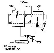
The basic applicator system and the method relating
thereto, as shown in Figs S and 6, consists of two
identical metallic rectangular sleeves 70, spaced from
one another by a gap 72 Other shapes, such as
cylindrical, elliptical, or square could be used They
are placed concentrically around the torso-simulating
phantom 74 As will be shown, heating occurs
lo principally in the gap region between the two sleeves
The sleeves dimensions (width and heigbt) are typically
30% to 50% greater than the torso so that the applicator
sleeves allow a relatively large air gap 76 to exist
betwe_n the patient and the metallic sleeves
lS Th~ two sleeves 70 surrounding the torso 74 are
electrically connected to each other, in the example, by
a coil 78~ The inductance of the coil and the`capacity
developed between the sleeves and the torso form a
rQsonant circuit through which RF power 77 can be
appli~d as s~own The RF en-rgy can be coupled directly
to t~- sl~-v s by an impedance matching circuit and a
bolus, by tap coupllng of the RF energy through one of
thQ inductors, (as shown in Figure 6) or by tap coupling
of tho RF energy employing the shield plates discussed
b-lo~ as ~ ground return
Evon tnough the sl~ev~s surrounding the torso are
~mall in teros of wavelength, a non-uniform E-field
distr~bution occurs in tho phantom cross-s-ction if the
two sle~ves are simply resonated with an inductor
attach~d at a single point to each sleev- as shown in
Fig 6 The resonant condition produced by the
sleeve/torso capacity and inductor is also sensitive to
movemont and torso size
Any E-field asymmetry and resonance sensitivity can
be corrected by the proper placement of additional
inductive and capacitive loading as shown in the
-12-
- 66-~9
~32~
alternative embodiment of the invention depicted in
Figs 8 and 9 The two sleeves 70 surrounding the torso
74 are electrically connected, in the figures, by four
coils 78 in conjunction with eight identical capacitors -
80 and two shield plates 82 The shield plates 82 are --
placed along both sides of the applicator between the -
phanto~ ond the applicator sleeves Electrically, the
shield plate surfaces form equal capacitancQ to both
sleeves so that a neutral RF potantial exists on the
shield plates, i.Q-, they are at ground potential By
positioning the plates as shown in the figures, the E-
field level around tha minor axis of the elliptical
phantom was reduced to a level equal to tbat established
elsewhere
The addition of the coils and fixed capacitors are
arranged so that the field distribution around the
sleeves is very uniform Likewise, the added càpacitive
loading stabilizes the resonant circuit so that it is ;
not significantly affected by patient to patient
20 variation `;
In a prototype of the present invention, the
circuit was r~sonatod at 27 12 MHz ThiQ frequency
rosult-d in conv ni~nt inductor and capacitor values and
good coupling to the torso was possible Since 27 12
NHz is also an ISM froquoncy, its use does not require a
scraen roo~ to furth-r mini~izo RF radiation The same
applicator principle~ howQver can be used at other ~`
fr qu ncie~ by prop r choico of the circuit element
values
Th- elongatQd elliptical cross-section phantom 74
was u~-d to make RF E-field and thermal measurements in
a salino tank with the new applicator because it more
noarly duplicated the human torso The resulting
electric field patt-rn was measured as shown in Fig 10 ;~;
Differencos in th- right and left side field-strength
response shape may be seen However, since the levels
-13-
; . .. :.: .
:' .'' ' .'
": ", ..
,'.` : ' , ~'
` ~324414 66-~9
did not exceed that produced in the center, it is not
considered a problem
Fig 10 was plotted in terms of the relative
Specific Absorption Rate, SAR The tank was ~illed with
a saline solution where the salt content was adjusted to
provide the approximate conductivity of human muscle
tissue at 27 M~z, i e , 0 62 mhos per meter
T~e corresponding heating patterns for two
different heating times are shown in Figs 11 and 12 and
the plots represent the ~easured thermal increase The
thermal patterns were measured in the same tank as used
for the E-field measurements but with the tank filled
with finely powdered silicon saturated with a saline
solution Again, the required salinity was
experimentally determined, by measurement, to produce a
phanto~ conductivity equivalent to muscle tissue
Fig~ 11 shows the thermal response a~ter applying
800 watts for 8 minutes Fig 12 shows that a similar
heating pattern was obtained when the duration was
increased to 15 minutes As is shown, relatively
uniform heating i~ obtained at any depth in thQ desired
cros~-~ection The thQrmal increaæe in the center of
the phantom was approximately 15% less than that
obtained at th~ bottom surface, but it was also about
10% greator than that ~t the top surface
T~e r lative SAR E-field mea~urement~ of Fig 10
~hows th~t ~ contrally located tumor (at 10 cm depth)
would receiv~ essentially the ~ame SAR within
mea~urement accuracy a~ that ob~-rved at the top and
botto~ surfac-s, i e , a very uniform oxcitation pattern
that s~ould result in a unifor~ heating pattern; the
ob~ect of thi~ invention
The thermal differences noted in Fig~ 11 and 12,
while minor when compared to other methods of heating,
appear to be due to an inadvertent variation in the
conductivity of the phantom material Following the
-14- ~
132~ 66-~9
thermal experiments, sample conductivity measurements
were made as follows top -- o 50 mhos/m, center -- 0 68
mhos/m and bottom surface -- o 85 mhos/m.
It is important to note that maximum heating - -
occurred in the material having thQ higher cond~ctivity
of muscle tissue This characteristic is a very
desireable feature since it discriminates against the
heating of fat a lower conductivity tiSSUQ that often
heats excessively while attempting deep heating
An a`-ernate serie~ of embodiments employing the
present invention is shown in Fig 16, 18, 20, and 22
Those shown in Figs 16 and 18 deposit RF energy in a
nearly uniform manor throughout a cross-section o~ the
human torso without the undesired characteristics of
many devices Figure 20, an abbreviation of the above
two applicator~, forms a very convenient device that
also provides deQp penetr~tion but favors~ the side
nearest the applicator plates ~"
The basic applicator system and the method relating
20 thereto of thQ alternate embodiment, as shown in Fig `~
16, consiQts of four large rectangular thin metal plates ``
82 and 8~, spac d from one another by a gap 86 They are
placed abov~ and below th- torso-simulating phantom 88
Th~ plat-s ar~ 20 to 24 inch-s long, i e , so as to
xc- d th~ body width The s~aller plate dimension is
10 to 12 inches m e plates are spaced 2 to 4 inches ``~
above and below the body -Qurfac- 88 allowing an air gap
The low~r plat-~ 82 can be imbedded in the patient
table m ~ dimansion~ given are typical and can be
varied considerably with minor effect
Th~ plat ~ becom part of a resonant circuit by
placing coils 95 across the gap and connecting them to `~
the lower plates as shown RF power i-~ then applied via
the coaxial lln- 94 The lower plates 82 are connected
to the upp-r plates 84 by ~etal straps 92 so that they
are on~ ~etallic structure That is, the upper and
-15- `
-
...~". . .
"~ .
~` 66-Ç9
132~14
lower plates are at the same RF potential The two sets
of plates 82-84 are connected by the coils 95 and RP
I energy is coupled to one of the coils as shown at 94.
Thus the plates on opposite sides of the gap produce a
di~ference of potential across the gap region 86 that is
an aperture or RF coupling mecbanism through which
energy is transferred to the body The relatively large
s~rfaces of the plates, in terms of body dimensions,
provide a large distributed capacitive coupling to the
body on eith~r side of the gap region that provides an
efficient aperture through which the RF ,energy is
launched into the body This is further verified with
~easurement dat~
The 4-plate version of the pr~sent invention also
extends over the torso in a non-contacting manner but
has no side plates aQ shown in Fig 5-9 This
configuration eli~inates excessive ~ide heating of
clliptical shapes whil~ still retaining the ability to
produce central heating
Th~ ~bre- plat- version of thQ present invention as
shown in Fig 18 will also produce an E-field
distribution nearly a~ uniform aQ that obtained with the
four plato ver~ion B~cause the plates are large and
extand over a significant portion of the body, the three
2S plat- vorsion is ~uch mor convenient in a clinical
sotting By r moval of the on- plate (that would
nornallr protrud- over the necX-nosQ region when heating
a c~ast tu~or), tha region near th- patient's face is
unobstruct d ~aking the procedure much less threatening
for tho pat nt
Tbe two plata version of the present invention is
-~hown in Fig 20 Both plates can be placed in the
patiQnt table so that it is simply necessary to position
the pati~nt so that the portion to be heated is over the
gap region
-16-
~':.
1324~1~ 66-49
E-field intensity patterns, that are representative
of the heating patterns, were measured while using the
present inventions These are shown in Figs 17, 19, and
21 where central heating is uniform to within 8 7% with
four plates, 11.1% with t~ree plates and 20% with the
use of two plates ~ -
With reference to Fig 23, the t~ermal performance
of the present invention was demonstrated by heating a
125 pound sedated pig 96 The pig was placed on its
10 side and positioned with its mid-section in the gap of --
the three plate version o~ the present invention A
catheter 98 was inserted through the mid-section into --
which a ~iberoptic thermal probQ was inserted and moved
to various locations to obtain a thermal profile ~-
~emperature measurements were made before heating and
after 15, 30 and 45 minutes of heating as shown in ;~
Figure 23 ~s may ~e seen, the upper surface~ (skin and
thick fat lay~r of a pig~ was not superficially heated,
as would be the case if signi~icant perpQndicular E-
20 fields w re pres nt The ther~al pattern is also ~`
remarkabl~ uniforo, espQcially when considering the
heterog neous body ~aterial in the cross-section T~us
the over~h~lming utility of the present invention is
authentic~t d
In t~e foregoing description of the present
inv ntion, ~ pre~err~d embodiment o~ the invention has
been disclosed It is to be understood that other
mechanical and design variations are within the scope of
the pr-sQnt inv ntion Accordingly, the preQent
invention i~ not limit-d to the particular arrangement
which h~s b~en illustrat-d and described herein ~;
DOCS 06649PAT OlD -~
:
: :~
-1?-
:" . :.'`'. -
,' ;, '.
''' '' ''~''
', ~-.''''