Language selection

Search

Patent 1324765 Summary

Third-party information liability

Some of the information on this Web page has been provided by external sources. The Government of Canada is not responsible for the accuracy, reliability or currency of the information supplied by external sources. Users wishing to rely upon this information should consult directly with the source of the information. Content provided by external sources is not subject to official languages, privacy and accessibility requirements.

Claims and Abstract availability

Any discrepancies in the text and image of the Claims and Abstract are due to differing posting times. Text of the Claims and Abstract are posted:

  • At the time the application is open to public inspection;
  • At the time of issue of the patent (grant).
(12) Patent: (11) CA 1324765
(21) Application Number: 1324765
(54) English Title: TURBINE BLADE WITH INTEGRAL SHROUD AND METHOD OF ASSEMBLING THE BLADES IN A CIRCULAR ARRAY
(54) French Title: AUBE DE TURBINE A ENVELOPPE INTEGREE, ET METHODE DE MONTAGE CIRCULAIRE DES AUBES
Status: Expired and beyond the Period of Reversal
Bibliographic Data
(51) International Patent Classification (IPC):
  • F01D 5/00 (2006.01)
  • F01D 5/22 (2006.01)
(72) Inventors :
  • PARTINGTON, ALBERT J. (United States of America)
  • WARNER, RONALD E. (United States of America)
(73) Owners :
  • WESTINGHOUSE ELECTRIC CORPORATION
(71) Applicants :
  • WESTINGHOUSE ELECTRIC CORPORATION (United States of America)
(74) Agent: OLDHAM AND COMPANYOLDHAM AND COMPANY,
(74) Associate agent:
(45) Issued: 1993-11-30
(22) Filed Date: 1983-11-21
Availability of licence: N/A
Dedicated to the Public: N/A
(25) Language of filing: English

Patent Cooperation Treaty (PCT): No

(30) Application Priority Data:
Application No. Country/Territory Date
446,093 (United States of America) 1982-12-02

Abstracts

English Abstract


ABSTRACT OF THE DISCLOSURE
A circular array of rotatable blades formed from
blades having an integral shroud with a leading planar
surface and a trailing planar surface, the leading planar
surface being generally parallel to an axial radial plane
passing through the center of the root of the blade and
the trailing planar surface, if extended, intersecting the
axial radial plane passing through the center of the root
of the blade to form an angle generally equal in degrees
to 360 divided by the number of blades forming the cir-
cular array.


Claims

Note: Claims are shown in the official language in which they were submitted.

What is claimed is:
1. A plurality of rotatable blades to be dis-
posed in a circular array on a turbine rotor, said blades
comprising a root portion which fastens said blades to
said rotor, an air foil shaped blade portion having a lead-
ing edge and a trailing edge and a shroud portion made
integral with the blade portion and disposed on the radially
outer end of the blade portion;
said shroud portion having a first planar surface
and a second planar surface, the first planar surface being
disposed generally parallel to an axial radial plane passing
through the central portion of the root portion and the
second planar surface if extended forming an angle with
said axial radial plane generally equal in degrees to 360
divided by the number of blades forming said circular array.
2. A plurality of blades as set forth in claim 1,
wherein the first planar surface is generally on the leading
side of the blade.
3. A plurality of blades as set forth in claim 2,
wherein the first planar surface extends slightly beyond
the blade portion of the blades.
4. A plurality of blades as set forth in claim 2,
wherein the trailing end of the blade portion extends beyond
the second planar surface on said shroud portions.

Description

Note: Descriptions are shown in the official language in which they were submitted.


132~76~
TURBINE BLADE WITH INTEGRAL SHROUD AND
METHOD OF ASSEMBLING THE BLADES
IN A CIRCULAR ARRAY
BACKGROUND OF THE INVENTION
This invention relates to turbine blades and
more particularly to rotating blades for a turbine.
In steam turbines arrays of rotating blades are
often joined together at their tip by a shroud ring which
is normally riveted to the blade via a tenon made integral
with the blade. The tenon being an abrupt change in
cross-section of the blade is subject to stress cracking
together with bending moments imposed by the shroud ring
and provides crevices wherein corrosion products are
accumulated which often results in corrosion cracking,
however, the shroud rings greatly reduce blade vibration.
SUMMARY OF THE INVENTION
In ge~eral, a plurality of rotatable blades
disposed in a circular array, when made in accordance with
this invention, comprise blades having a root portion,
which fasten the blades to the rotor, an air foiled shaped
blade portion having a leading edge and a trailing edge,
and a shroud portion made integral with the plade portion
and disposed on the radially outer end of the blade por-
tion. The shroud portion has a leading planar surface and
a trailing planar surface. The leading planar surface is
disposed generally parallel to an axial radial plane
pa~sing through the central portion of the root portion
and the trailing planar surface if extended forms an angle
'~
-

132476~
2 50,707
; with the radial axial plane passing through the center of
the root portion generally equal in degrees to 360 divided
by the number of blades forming the circular array.
BRIEF DESCRIPTION OF THE D~AWINGS
The objects and advantages of this invention
will become more apparent by reading the following de- -
i~ tailed description in conjunction with the accompanying -~
drawings, in which:
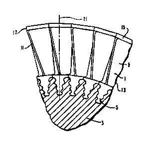
Figure 1 is a partial sectional view of a cir-
cular array of rotatable blades disposed in a rotor; -~
Fig. 2 is an elevational view of a blade;
Fig. 3 is a plan view of the blade; and
Fig. 4 is an elevational view of the blade.
DESCRIPTION OF THE PREFERRED EMBODIMENT
Referring now to the drawings in detail and in
particular to Fig. 1, there is shown a portion of a cir-
cular array of rotatable turbine blades 1 disposed in a
portion of a turbine rotor 3.
As shown best in Figs. 2, 3 and 4, each turbine
blade comprises a Christmas tree shaped root portion 5
which registers with a similarly shaped groove in the
rotor 3 to fasten the blades 1 to the rotor 3. To prevent
axial movement of the blades, a pin tnot shown) fits a
semicircular groove 7 in the blade 1, which registers with
a semicircular groove in the rotor 3 (not shown).
Extending radially outwardly from the root portion
5 is an air foiled shaped b}ade portion 9 having leading
and trailing edges 11 and 13, respectively. Disposed radi-
ally outwardly of the blade portion 9 and made integral
therewith is a shroud portion 15. The shroud portion 15
has a leading planar surface 17 and a trailing planar
surface 19. The leading planar surface 17 as indicated
by the line 20 which represents the extension of the
planar surface 17 is generally parallel to an axial radial :
plane 21 passing through the center portion of the root
portion 5. The trailing planar surface 19 if extended a
indicated at 23 forms an angle a with the radial axial plane -
generally equal in degrees to 360 divided by the number :~
of blades in the circular array.
":-,

132476~
The leading planar surface 17 extends a few
thousandths of an inch beyond the leading edge of the
blade portion 9 and the trailing edge 13 of the blade
portion 9 extends substantially beyond the trailing planar
surface 19 of the shroud portion 15.
The outer periphery of the shroud portion 15 is
machined to form a cylindrical ring which cooperates with
labyrinth seals to form a rotating seal.
The method of forming the circular array of
blades 1 comprises the steps of forming each blade with a
shroud portion 15 made integral with a blade portion 9,
the shroud poxtion 15 having a leading planar surface 17
and a trailing planar surface 19;
forming the leading planar surface 17 so that it
is generally parallel to an axial radial plane 21 passing
through the center portion of the root portion 5;
forming the trailing planar surface 19 so that
if it were extended, it would form an angle with the axial
radial plane passing through the central portion of the
root portion 5 generally equal in degrees to 360 divided
by the number of blades in the circular array;
forming the leading planar surface 17 on the
shroud 15 so that there is several thousandths of an inch
interference when assembling adjacent blades;
machining each leading planar surface 17 indiv-
idually to remove just enough material to allow assembly
of the blade adjacent the trailing side of the adjacent
blade, so that the blade can be assembled with the center-
line of the blade in a radial plane; and
machining the outer peripheral surface of the
shroud portion 15 of the circular array of blades to form
a cylindrical surface which cooperates with a labyrinth
seal to form a rotating seal.
The blades and method herein~efore described
advantageously form a complete shroud ring greatly reduc-
ing blade vibration due to the snubbing and damping of the
abutting shroud portions and eliminating riveted tenons,
., ~'''-'
.~ . , .

~ ` 132~76~
which accumulate corrosive products and ar subject to
corrosion and stress cracking.
' " ' :'
., . ,' "~'
"'',`',''''',',''.'','""~.,''''''','.', ;;:

Representative Drawing
A single figure which represents the drawing illustrating the invention.
Administrative Status

2024-08-01:As part of the Next Generation Patents (NGP) transition, the Canadian Patents Database (CPD) now contains a more detailed Event History, which replicates the Event Log of our new back-office solution.

Please note that "Inactive:" events refers to events no longer in use in our new back-office solution.

For a clearer understanding of the status of the application/patent presented on this page, the site Disclaimer , as well as the definitions for Patent , Event History , Maintenance Fee  and Payment History  should be consulted.

Event History

Description Date
Inactive: IPC from MCD 2006-03-11
Inactive: Adhoc Request Documented 1996-11-30
Time Limit for Reversal Expired 1996-06-02
Letter Sent 1995-11-30
Grant by Issuance 1993-11-30

Abandonment History

There is no abandonment history.

Owners on Record

Note: Records showing the ownership history in alphabetical order.

Current Owners on Record
WESTINGHOUSE ELECTRIC CORPORATION
Past Owners on Record
ALBERT J. PARTINGTON
RONALD E. WARNER
Past Owners that do not appear in the "Owners on Record" listing will appear in other documentation within the application.
Documents

To view selected files, please enter reCAPTCHA code :


To view images, click a link in the Document Description column. To download the documents, select one or more checkboxes in the first column and then click the "Download Selected in PDF format (Zip Archive)" or the "Download Selected as Single PDF" button.

List of published and non-published patent-specific documents on the CPD .

If you have any difficulty accessing content, you can call the Client Service Centre at 1-866-997-1936 or send them an e-mail at CIPO Client Service Centre.


Document
Description 
Date
(yyyy-mm-dd) 
Number of pages   Size of Image (KB) 
Cover Page 1994-07-16 1 40
Abstract 1994-07-16 1 16
Drawings 1994-07-16 1 44
Claims 1994-07-16 1 56
Descriptions 1994-07-16 4 208
Representative drawing 2002-02-22 1 10
Prosecution correspondence 1986-05-30 1 36
Courtesy - Office Letter 1993-09-21 1 53
Prosecution correspondence 1986-05-30 4 134