Note: Descriptions are shown in the official language in which they were submitted.
132~847
~3~CKGROIJND OF THE INVENTION
1. Field of the invention.
The present invention relates to the field of color
displays for computer systems and, more specifically, to
the field of graphical color presentation and drawing
systems.
2. Prior Art.
A number of methods of presentation of color
information to display devices are well kno~n in the art.
In general~ such display dev~ces may be divided into two
categories; red-green-blue (RGB) devices and NTSC or
similar devices. In a RGB device, color information is
presented to a display as three separate units of color
! information; a first unit of information representing the
intensity of the red color gun of the display, a second
unit representing the intensity of the green color gun of
t~e display and a third unit representing the intensity of
the blue color gun of the display.
NTSC devices (and their ~quivalents under other
standards such as PAL) present color information to a
display generally by phase-shifting a waveform some
predetermined number of degrees from a reference signal.
The color display, such as a television set interprets
color based on the number of degrees the waveform is out of
phase with the reference. Such systems may further
control the intensity of the color by controlling the
amplitude of the color s~gnal.
The present invention relates to RGB display devices
and colors systems.
In a RGB color system, a display may be controlled by
presenting bits of color information to drive digital-to-
., ... .._ ..,
1324847
analog converters which in turn produce three analog colorsignals which control the red, green and blue guns of a
display. Typically, 24 bits of color information may be
- used; 8 bits representing red, 8 bits representing green
and 8 bits representing blue. Using 24 bits of color
information allows over 16 million ~224) colors to be
produced.
In a typical computer system employing a color
display, a device called a "frame buffer" is utilized.
frame buffer is a memory for storin~ color information
corresponding to eacb pixel on the display. A frame buffer
may store 24 bits of information per pixel and the 24 bits
of information may be used to directly control the color
display. Such a system is typically termed a direct color
system. However, use of a full 24 bit frame buffer
requires a large amount of memory space and leads to other
processing inefficiencies As an example of the amount of
memory space required, many known displays, such as a
display w~ich may be utilized with the Macintosh Il, have
displays comprising 640xg80 pixels.
It is known to utilize a frame buffer having less than
24 bits of color lnformation per pixel. Such a system may
store for example 1, 2, 4, or 8 bits per pixel for color
presentation. The bits of information from the frame
buffer are used to address a color look-up table (CLUT).
The data outputs of the CLVT are the RGB colors signals or
their digital equivalents. The use of the CLUT offers a
number of advantages. For example, a smaller amount of
memory may be used for a frame buffer and colors on the
display may be adjusted by ad~usting the data content of
the CLUT.
The present invention relates to a method in apparatus
for presentation of color information to a dlsplay
13248~7
utilizing a color look-up table. Such a device may be
termed a CLUT device.
A third method for presentation of color information
to a display is commonly termed a fixed device. A fixed
device, though similar to a CLUT device in featuring an
index frame buffer, does not have a changeable CL~T. An
example of a fixed device is the IBM Enhanced Graphics
Adapter (EGA) standard.
One objective of the present invention is to develop
color graphics capable of producing image-quality graphics,
i.e. the ability to display a reasonable likeness of a
color photograph in a microcomputer system.
A second o~ective of the present invention is to
avoid speed and performance degradation in the computer
system for users not utilizing such image quality graphics.
~or example, a user utili~ing a word processing system has
little need for high quality color graphics.
A third ob~ective of the present invention is to allow
a user to cut graphics created in a first graphic mode and
paste t~e graphics into a display created ln a second
graphlcs mode.
These and other ob~ectives of the present invention
are described in more detail wlth reference to the Detailed
Descrlption of the Inwention and with reference to the
dzaw1ngs.
1324847
SUM~RY OF T~E TNvENTloN
The present invention relates to the field of color
- graphics systems for computers and has specific application
$n red-green-blue color systems. The present invention
discloses use of a table for translating color lnformation
which may be received from an application to an index
value. The index value may ~e stored in a frame buffer or
otherwise used by the computer system. In the present
invention, index values stored in the frame buffer may be
used to address a color ~ook-up table which provides color-
information for a display or other device.
The present invention discloses a method for creating
the color-to-index (or inverse color look-up~ table which
provides for seeding an array with color information from a
color look-up table~ Each ~seed~ in the array is then
grown outward and data elements ad~oining the seed are
associated with the same color as the seed from the color
look-up table. The method of the present invention offers
speed and processing efficiency advantages of methods of
calculating distances between points in the array to
determlne assignment of colors.
Utilizing the lnverse color look-up table of the
present invention, color graphics may be created $n one
color mode and displayed in a second color mode. The
graphics when displayed in the second color mode will
~ provide an approximation of the colors as originally
; created.
The present invention further provides method for
ar1thmet1cally ranlpulating colors on a dlsplay.
.
-
- i32~847
Accordingly ln ono aspect, tho presont
invention residos in a method for provlding a color
graphics ~n a computer ~ystom, said method comprlslng
the steps of providing said graphics system with a
first RGB color informatlon, said first RGB color
information comprlsiny X bits, addressing a first tablo
with said first RGB color information ~aid eabls
comprislng 2Y entries, wherein when Y io le~s than X,
~aid first table provides an index valuQ in rospon~ to
Jald addre~sing and storing said index valuo.
In another a~pect, the present invention
resides $n a color graphics JystQm having a first
memory means for storing a fir8t tabl~, said first
table for providing a fir~t index value in respon~e to
rocoiving a fir~t red-green-blue ~RGB) color
information, a Jccond m~mory moan~ for qtoring a second
table, the sw ond tablQ rQprQsenting colors existing in
a predeterminod noighborhood in RGB color ~paco, tho
oocond memory moan~ providlng a socond index value
rospon~lve to receiving th~ firJt indox value $f therQ
i~ an entry in the ~econd table corr~sponding wlth the
fir~t index value, and if the color reprosented by the
~econd indox value i8 closer ln RG~ color space to the
: first RGB color information than tho color represQntodby the fir~t index value, the ~econd index value
becoming the flrst indox value, and a thlrd memory
mean~ for ~torlng Jald first indox voluo, said thlrd
memory mean~ havlng a plurality of storoge loc~tion~
corresponding with plxel locatlons on a display moans.
In a further aspect, the pre~ent inventlon
reslde~ in a method for building an invorso color look-
up table in a color graphlcs system, ~ald inverse color
look-up tablo for accopting a8 an addross input RGB
1324847
color information and providlng as a data output lnd~x
information for indexing a color look-up table, said
method comprising the steps of initiallzing an array of
date elements, each of said data ele~entJ for storing
said index information, each of said data alemants
corresponding to a color positlon in RGB color ~pace,
~toring a firRt lndax v~lue in sald array, sald firQt
index value corre~ponding to an index for said color
look-up table, ~ald first lndex value ~tored ln a fir~t
of aaid data element~, ~aid fir~t data alemant
correspondlng to a color represented by a said first
index value in said color look-up table, storing an
addra~ of said fir~t data alemont in a queua means for
later proces~lng, for a ~acond of ~aid data aloments,
1~ ~aid sacond of said data elemQnts logically n~xt to
~ald fir~t data element in RG~ color ~pace, determinlng
whath~r ~aid ~econd data alement ha~ bean aosigned an
indax value, if ~aid second data elomQnt has not been
a~ign~d an index value, assigning said ~ocond data
elem-nt ~aid fir~t lndax valuo and ~toring an address
for sald sacond data element in said ~ueue meana.
- 4b -
, ~ . ~- - . - ,
- 13248~7
F~F DESCRIPTION OF ~rHE DRAWINGS
.
- Figure 1 is a block diagram illustrating an inverse
color look-up table as may be utilized by the present
invention.
Figure 2 is a diagram illustrating red-green-blue
~RGB) color space.
Figure 3 is an illustration of a point in RGB space
showing the point and its orientation to its neighboring
points.
Figure 4 is a flowc~art illustrating a method of the
~ lS present invention.
Figure 5 is a diagram illustrating a first-in, first-
, out queue as may be utilized by a method of the present
invention.
Figure 6 is a flow diagram illustratinq a method of
the present invention.
Figure 7 is a flow diagram illustrating a method of
~ 25 the present invention.
K ` Fl~ure 8 show-~ ~n example of a hldden color hash
'~ table.
132~8~7
DE;~ ,ED DESCRIPTIO`i OF THE PRESENT It~VENTION
A color graphics system for use with a computer is
described. In the following description, numerous specific
details are set forth such as number of bits, etc., in
order to pro~ide a thorough understanding of the present
invention. It will be obvious, ~owever, to one skilled in
the art that the present i~ention may be practiced without
these specific details. In other instances, well known
circuits, structures and techniques have not been described
in detail in order not to ~necessar~ly obscure the present
invention.
The present invention relates to color display systems
1~ for computers and is embodied in the Nacintosh II Color
QuickDraw system available from Apple Computer, Inc. of
Cupertino, California, t~e assignee of the present
inventlon. The present invention provides lmage-quality
qraphics in a microcomputer environment.
As one ob~ective of the present invention, it is
desired to provide such ~mage-quality graphics while not
degrading speed and performance of the computer system for
users not utilizing such i~age-quality graphics. In
meeting this ob~ective, the present invention discloses use
~5 of hardware and software means which support a number of
different color modes on a display ranging from a
monochrome mode where only two colors may be displayed, to
intermediate modes where 4 to 256 colors may be displayed,
to a full color mode where Dore than 16 million colors may
be displayed simultaneously. In modes which support fewer
colors, speed may be maximized since less memory must be
manipulated. In fu~l color mode, image-quality graphics
may be achieved while having a cost tradeoff against speed.
132~8~7
The present invention allows a user to dynamically change
color modes to tailor color and speed capabilities of the
system to suit t~e users immediate requirements.
As one important aspect of the present invention it is
desired to allow a user to cut graphics created in one
application and paste the graphics into another
application. Typically, a user of a Macintosh system may
cut grap~ics from a display by marking the graphics to be
cut using any one of a number of methods and selecting a
cut function. Alternatively, the user may mark the selec~n
and select a copy function. The copy funct~on leaves the
original display intact. In either case, a copy of the
graphics are kept in what is termed the users clipboard.
~he user may t~en change applications and paste the
1~ graphics from his clipboard into the new application. The
; present invention allows graphics which may have been
created in, for example, image quality mode to be displayed
in another mode such as one of the intermediate modes. The
color graphics system of the present invention will display
~0 the graphics in the best approximation available utilizing
the current color mode on the available output device.
As a another aspect of the present inventlon, it
desired to provide capability for mixing of colors which
are presently on a display with other colors. As examples,
a user may wish to blend two colors, add two colors
together or s~ubtract one color from another color. Such
functionsare termed arithmetic transfer modes.
.TNVF.R~F. COLOR LOOK-UP TABLE
The present invention utilizes an inverse color look-
up table (ICLUT) to accomplish these and other ob~ects of
the present invention. The basic structure of the ICLUT
101 is further disclosed with reference to Figure 1. The
. .
- 132~8~7
purpose of the ICLUT 101 iS to allow color information 103
to be used as acldress inputs to the ICLUT 101 and to
provide as data outputs 104 index values to be stored in a
frame buffer. The ICLUT may be considered to be a one-
dimensional array of index values which correspond to RGBcolor input values.
In the preferred embodiment, RGB colors are specified
using 48 bits of color information 102. The 48 bits of
color information 102 comprise 16 bits of red color
information 10~, 16 bits of green color information 106 and
16 bits of blue color information 107. Within each of the
red, green and blue color fields, 105, 106 and 107
respectively, the value is treated as binary fraction. The
range of eac~ value is from 0.0 to approximately 1.0, where
0.0 represents absence of the color and 1.0 represents the
maximum value of the color component. The actual data in
the field is the fractional part of the actual value with
the leading zero implied. The fractional data is left-
~ustified in the 16-bit field so that the most significant
bit ls always the hig~est bit of ehe field.
Tbe 48-bit RGB color information field 102 may be used
as an address input to an lnverse color look-up table.
However, in practice, use of the full 48-bit RGB color
information field ~ould require an ICLUT with an address
space of 248 entries. Such a large table is not generally
desirable in computer systems as may be utilized by the
present invention.
T~e preferred embodiment utilizes a reduced number of
bits from each color channel to approximate the 48-bit RGB
color information field. Specifically, in the preferred
embodiment normally only four bits are used from each color
channel, 5uch as bits 110 ~or red, 111 for green and 112
1~2~8~7
for blue. use of four bits for each color requires an
ICLUT address space of 212 or 4096 entries.
Since, as previously described, the color component
values for red, green and blue, 105, 106 and 107,
5 respectively, are left-justified fractions, forming of the
12-bit address input 103 to the ICLUT is a relatively
simple matter of stripping the leading four bits, 110, 111
and 112 from each of the red, green and blue color fields.
The data output 104 comprises eight bits of index
10 information to be stored in a frame buffer or otherwise
utilized by the computer system. The index information may
be used in the conventional manner as an address input to a
color look-up table (CLUT~ to generate RGB signals for a
display.
~nl~;'rRU~TIOl~ OF T~ NVERSF~ CO~O~ LO~K--UP TABLE
- The present invention discloses methods of
`A constructing an inverse color look-up table ~ICL~T). As
bac~ground to the described methods of the present
20 invention in constructlng an ICLUT, a description of RGB
color space is useful~ The RGB color ~odel is based on
fact that radiated color is composed of a mixture of red,
green and blue light. Visible colors are the result of
t varying mixtures of these three primary color components.
- 25 For example, mixing equal amounts of the primary cQlors
creates white light, mixing green and red light creates
yello~, absence of all components creates black, etc.
Theoretically, any visible color can be represented using
an RGB triple.
As shown by Flgure 2, RGB color space can be
represented as a three dimensional cube 200 with each of
` the colors, red, green and blue, represented by one o the
cube's axis, 201, 202, and 203, respectively. Any
9 ,.
1~2~847
- arbitrary c~lor n,ay be represented by a point somewhere in
the cube. For example, point (o~o~o) 210 may represent
lack of all color components and corresponds with t~e color
black. Point (1,1,1) 211 represents maximum intensity of
all color components and results in the color white.
Points (l,0,0) 212, (0,1,0) 213, and (0,0,1) 214) represent
maximum intensity of each of the three primary colors and
lack of the other two color components resulting in the
colors red, green and blue, respectively.
It ~s worth noting that the color model used for
devices uhic~ radiate light, such those used in conjunction
with the present invention, may be termed on additive color
model. Other color models, sucb as a sub~ractive color
model used for media which absorbs light, follow different
rules and may utilize different "primary~ colors. However,
the present invention's methods and apparatus may be
equally applicable to other color models.
In constructing an inverse color look-up table, one
ob~ectlve is to construct the table usin~ as few of the
computer resources as possible and to construct it as
quic~ly as possible. In general, in computer systemsas may
utillze the present inventlon, the ICLUT cannot be pre-
calculated and saved in a memory device or on disk because
the available system colors may be changed at any time.
For example, the available system colors are changed each
time the number of bits of information used to represent a
pixel stored in the indexed frame buffer is changed. As
previously described, the number of bits per pixel may be
changed in the present invention when changing from
; 30 application-to-application or at such other time as may be
desired. The available system colors may also be changed
when color space ls ~ein~ divided up in a different
fashion. For example, rather than evenly distributing all
,. 10
132~8~7
colors from the RGB color space in the ICLUT, emphasis may
be placed on green and various tones of green. Generally,
any change to the color look-up table will requ~re
rebuilding the inverse color look-up table.
One method for building an ICLUT comprises generating
each RGB permutation and calculating its distance from each
color in the color look-up table. The addxess in the
color look-up table of the color which is closest in
distance from the RGB permutation is selected as the index
address to be stored ~n the inverse color look-up table.
Such a method ultimately requires a large number of
calculations and substantial amounts of time.
The present invention discloses a geometrical solution
to building the ICLUT which takes advantage of the three-
I5 dimensional nature of RGB space as discussed in connectionwith Figure 2. Generally, the method of the present
invention utilizes a three-dimensional array of elements
~hich simulates the RGB cube of Figure 2 and a queue of
elements to operate on. In concept, the present invention
may be t~ought of as selecting each of the colors in the
color loo~-up tsble and and blowing up t~e point in the
cube represented ~y that space as if the point were a
balloon. ~hen the balloons representtng each color in the
~color loo~-up table touch and cover all points in the cube,
25 the points inside eac~ balloon are assigned to the color in
the color loo~-up table represented by the point from which
the balloon origlnateld.
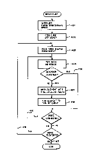
In operation, the method of the present invention is
described in more detail with reference to Figuxes 3, 4 and
5. ~igure 4 is a flowchart describing the above-mentioned
method of the present lnvention. The present invention
inltializes a three-dimensional array representing points
in RGB color space to an initial value which indicates the
' . 11
. .
13248~7
,_~
points are not yel: "owned" by a color, block 401. In
addition, a "shell" is built around the cube consisting of
an illegal value. The shell marks the boundaries of the
c~ .
The available colors from the color look-up table are
"seeded" into their appropriate positions in the array,
block 402. The seeding of the array comprises putting the
addresses (indexes) of each element of the color look-up
table into the position in the array corresponding to the
RGB value represented by the data value at that address
lindex) in the color look-up table. The RGB value is
truncated, in the preferred embodiment, to four bits
representing each of the primary colors.
The addresses in the array of each of these assigned
positions are added to the tail of a queue for later
processing as will be described below. Referring briefly
to Figure 5, a diagram illustrating the queue 501 is
lllustrated. For example, address A 504 in the array may
be assigned to the first color in the color look-up table.
Address A is added to the tail of the queue 503. Address B
505 may then be assigned to the second color in the color
look-up table and added to the tail of the queue 503. This
process continues with each of the colors (C.D.E...) in the
color loo~-up table.
After the array is seeded, the element at the front of
the gueue 502 is processed by flrst reading the element
from the queue, block 403. This element will be termed the
parent element. As lllustrated ln Figure 3, the parent 301
may be thought of as having six "neighborsn. The neighbors
comprise the elements in the array which are logically
immediately left of the parent 302, right of the parent
303, above the parent 304, below the parent 305, in front
of the parent 306 and behind the parent 307.
12
13~847
For each neighbor, a check is first made to determine
whether the neighb,or is assigned, block 404. A neighbor is
assigned if the value in the array has been set to an
address corresponding to one of the colors in the color
look-up table (and, therefore, is not still t~e value which
tbe array was initialized to at block 401). If the
neighbor has been assigned, branch 405, no further action
is taken with the particular neighbor and processing
continues with t~e remaining neighbors of the parent.
If the neig~bor has not been assigned, branch 406, the
neighbor's location in the array is marked with the same
address as the parent, block 40~ and the neighbor is added
to t~e tail of t~e queue, block 408. Adding the neighbor
to the queue is illustrated ~ith reference again to Figure
S showing a neighbor of A 506 being added to the end of the
queue.
Processing continues for each of the six neighbors of
the parent, branch 410. After all neighbors of the parent
have been processed, branch qll, the process continues for
eac~ successive element on the queue, branch 412. When the
queue is empty, branch 413, all elements in the array have
been assigned to a color in the color look-up table. The
resultinq array may be utilized as an inverse color look-up
table.
Nhile this method of constructing an inverse color
loo~-up table offers a number of inventive advantages such
as reducing the number of time-consuming calculations over
methods of purely calculating and comparing dlstance
relationships, a number of disadvantages exist. For
example, tbe method can lead to different approximations of
colors than would be found using distance calculations.
The implementation of the preferred embodiment attempts to
alleviate a number of these disadvantages through various
24847
methods. For example, the preferred embodiment alternates
the order of selecting neighbors wh~ch prevents the queuing
mechanism from favoring certa~n directions over others.
PRESF.NTA~ION QF COLORS IN l`HE PRESENT ~NVENTTON
Referring now to Figure 6, a block diagram
illustrating presentation of colors in the present
invention shown. In general, color information may enter
the system as RGB color information 601. In the preferred
e~bodiment as discussed previously, this RGB color
information 601 typically comprises 48 bits of color
information, 16 bits for each of the red, green and blue
components.
The RGB color information 601 is input to a process
602 for converting the color information to an index. The
process 602 utilizes the inverse color look-up table using
the RGB color information 601 as an input address and
obtaining the index into the color look-up table as a data
output. The index value in the preferred embodiment may be
1, 2, 4, or 8 bits long depending on the color mode
selected by the application. A l-bit index value allows
for two colors to be presented on the display, a 2-bit
value allows for four colors to be presented, a 4-bit value
allows for 16 colors to be presented, an 8-blt value allows
256 colors to be simultaneously presented. It will be
obvious to one of ordinary skill that a greater number of
blts may be stored as an index with a corresponding
increase in the number of available colors and memory
usage.
The index value ls stored in the index frame-buffer
memory at a location corresponding to the appropriate pixel
on the display.
14
-` 1324847
The index va:Lue may then be used as an input to a
process 604 which converts the ~ndex to a color for
presentation to the display 605. The processor 604 uses as
input to the color look-up table an index value from the
indexed frame buffer and generates as an output 24-bit RGB
color informat~on.
~ EN--coLoR HASH TABLE
Certain distributions of colors in the color look-up
table may cause colors to be "hidden" behind other colors.
This is because only t~e four most significant bits of each
of the red, green and blue color components are used in
building and addressing the ICL~T. Therefore, if two or
more colors exist in t~e color look-up table which differ
only in their 5th or greater bit, one of the colors has the
tendency to hide the other colors in the inverse color
loo~-up table. Typically, hidden colors are not an issue
where colors in the color look-up table are distributed
uniformly through the color space. However, when colors
are not distributed uniformly, ~idden colors may be
signlficant.
The present invention utilizes a hash table of hidden
colors. The ~ash table has one entry for each color in the
color mode. ThuS, if the current color mode uses 1 bit of
index information in the indexed frame b~ffer and,
therefore, has two colors, the hash table would have two
entries. For example, the first color may have a red
component wit~ the first flve most significant bits of
11001, green component with bits of 00011, and blue
component with bits of 10001. The second color may have a
red component with the first five most significant bits of
11000, green component with bits of 00010 and blue
component with bits of 10000. In the example, when
..
1324847
- utilizing only the most significant four blts one of the
colors would hide the other color.
The hash table of the present invention provides a
list of all such hidden colors for a particular color look-
S up table. When attempting to determine an index for a 48-
bit color, a check is made against the hash table to
determine whether the color is in the list of hidden
colors. If it is, an explicit distance test is performed
to determine the closest match.
For example, referrinq to Figure 8, a hash table is
s~own. The hash table 801 has 256 entries indicating it
has been built for a color look-up table with 256 entries
(8-bit color mode). In the example, color 4 802 hides
color 12 804, color 12 804 hides color 10 803 and color 10
803 hides col~r 4 802. Nhenever a 48-bit color is received
by the color-to-index process and an index of color 4
resul~s, an explicit distance test i5 done using the 48
bits of color information to determine whether the 48 bits
of color information is closer to color 4 802, color 10 803
or color 12 804. An index corresponding to the closest
color 4, 10 or 12 is stored in the indexed frame buffer.
The has~ table may be created when creating the
inverse color look-up table. During seeding of the table,
any colors from the color look-up table which, when
2~ truncated to 4-bits as in the preferred embodiment, would
occupy the same data element in the array may be consider
to hide one another. ~hen such a condition is detected, an
appropriate entry is made in the hash table.
~o~l~ s~ YYb~ Y~
As one lnventive advantage of the present invention,
colors on a display may be blended, added, subtracted and
otherwise arithmetlcally manipulated. Referring to Figures
132~847
6 and 7, an application or user may provide RGB color
information 701 for a pixel. The RGB color information 701
may be referred to as RUGuBu. The computer system may then
provide from the indexed frame buffer eight bits of index
information 702 corresponding with pixel I. The eight bits
of index information 702 are provided to the index to color
process 604 and a RGB value 704 is obtained. The R~B color
information 704 may be referred to a RiGi8i. T~e color
infonmation RUGUBu and RiGiBi are used as inputs to an
operation 606 and 706. The output of the operation 606 and
706 is RG3 color informaeion 708 which may be referred to
as R'G'B'. The R'G'B' color information may then ~e used
as input to the color to index process 602 and an eight bit
index value I' 710 for storinq in pixel memory is obtained.
The operation 606 and 706 may comprise a function such
as adding the RUGuBu and RiGiBi inputs where:
R' ~ Ru + Ri;
G' = Gu ~ Gi; and
B' - Bu ~ Bi~0 A subtraction function may yield:
R' - Ri - Ru;
G' - Gi ~ Gu; and
B' - 8i ~ Bu
A blend function (blend(~))may yield:
R' 3 (~) Ri + (1 - ~) Ru:
G' - (~)Gi + (l-~)GU; and
B' ~ (~)Bi + ~l-~)Bu; `
~here 05KS1-
~- 1324847
The arithmetic transfer mode functions are available in the
present invention by utilizing the inverse color look-up
table as discussed above.
Thus, an improved color graphics system for use with a
computer has been described. Although tbe present
invention has been described with specific reference to a
number of details of the preferred embodiment, it will be
obvious.that a number of modifications and variations may
be employed without departure from the scope and spirit of
the present invention. Accordingly, all such variations
and modifications are included within t~e intended scope of
the invention as defined by the following claims.