Note: Descriptions are shown in the official language in which they were submitted.
132~403-
':
~ITLE OF THE INVENTION
Method for Finishing a Work
BACKGROUND OF ~HE INVENTION
The present invention relates to a method for finishing a
surface of a work by electrolytic machining, and more
particulary to a method for finishing the surface having a
three-dimensional shape.
U.S. Patents 3,527,686 and 3,607,689 disclose
electrolytic machines. In the machine liquid electrolyte is
1~ continuously passed between an electrode and a work at a high
speed during machining, so that residual products such as
particles of eroded metal from the work, hydrogen gas, and
others are discharged from the gap between the electrode and
the work. However, in the case of the work having a
complicated three-dimentional shaped recess, it is impossible
to pass the liquid electrolyte through the gap having a
~; complicated shape at a constant speed. The accuracy of the
product is greatly influenced by the irregularities in the
electrolyte flow. In addition, the concentration of the
`!
electrolyte at an outlet of an electrolyte tank is different
; from the concentration at an inlet, even if the pressure of
the liquid is increased. Accordingly, it is impossible to
produce accurate products.
In order to eliminate such disadvantages, the applicant
proposed a system in which liquid electrolyte is not passed
through an electrolyte tank and discharged together with
... . .
.~ .
' ~ ' '' ' ' ~ i; ' ' '
. :
,; ~ .
,
~ ~ .
: '
r~
~32~103
residual products after application of pulses, and clean
electrolyte is supplied to the tank for the subsequent
process. However, pulses in the subsequent process are
applied while the electrolyte moves in the gap between the
work and the electrode. In such a state, flow rate of the
electrolyte in the gap i5 different in localities, so that the
electrolyte swirls in the gap. As a result, machining
condition is different in localities, so that patterns
dependent on the irregular flow of the electrolyte are formed
. ~
; 10 on the surface of the work, which result in deterioration of
~ surface quality of the work.
. .,
SUMMARY OF THE INVENTION
The object of the present invention is to provide an
:
electrolytic finishing method which may finlsh a
three-dimensional surface of a work to a product having a
lustrous surface with accuracy at high speed.
According to the present invention, there is provided a
method for finishing a work comprising positioning an
electrode to form a predetermined gap between the electrode
~ 20 and the surface of the work, supplying electrolyte to an
,
electrolyte tank so as to submerge the electrode and the work,
.~
~ applying pulses to the electrode, discharging the electrolyte
:
~ including residual products after one cycle of machining,
~; . .
re-supplying clean electrolyte to the electrolyte tank, and
applying pulses to the electrode after a predetermined period
of time for the next cycle of the machining.
~,
~ 2
... .
.
: .
. ;,.:
. :,...
., .
.
, : ,: :.
~325403
In an aspect of the invention, the machining is divided
into a first process and a second process, and a pulse in the
second process is set to a higher current density than the
^ first process, and a removing pulse having a higher current
. ,
density than the pulse in the first process is intermittently
applied during the first process.
The other objects and features of this invention will be
apparently understood from the following description with
reference to the accompanying drawings.
BRIEF DESCRIPTION OF DRAWINGS
Fig. 1 is a front view of an electrolytic finishing
machine according to the present invention;
Fig. 2 is a side view of the machine;
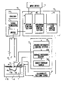
Fig. 3 is a block diagram showing a system of the present
invention, and
Figs. 4a and 4b show a block diagram showing a system for
~, ,
supplying current to an electrode.
DETAILED DESCRIPTION OF THE PREFERRED EMBODIMENT
Referring to Figs. 1 to 3, the electrolytic finishing
,, ~ . . . .
i~ 20 machine 1 has a work fixing device 3 in an electrolyte tank
15. A work 2 is mounted on a base 3a of the device 3 and
fixed thereto by an upper plate 3b and bolts 16 screwed in the
base 3a. An electrode 4 made of copper is secured to the
, ~,
lower end of a rod 17 of an electrode holding device 5. The
holding device 5 is operatively connected to an electrode
driving device 6 through an electrode driving direction
. .
- 3
. ' ~
.
' ;
: ,
,~:
;. . . , :
'. : . ' ' ~ . ~
~25403
~ converter 7. The converter 7 is arranged to change rotary
output of a motor 19 in device 6 into axial movement of the
rod 17
The work 2 has a three-dimensional recess 2a to be
finished, which has been formed by an electrical discharge
. machine (not shown) with the electrode 4.
As shown in Fig. 3, the driving device 6 has a rotary
:-. encoder 20, tacho-generator 21 and motor 19. Output signals
- of the encoder 20 and tacho-generator 21 are supplied to a
10 motor control section 9 of a control unit 12, and motor 19 is
operated by a control signal from the motor control section 9.
The control unit 12 has a machining condition control section
10 and an electrolyte flow control section 11.
.~ The system has a power source device 8 which comprises a
. ~
. 15 direct current source 22, a charge/discharge section 23, and a
. charge/discharge control section 24 for controlling the
i charge/discharge section 23. The charge/discharge section 23
:i; generates a pulse of a current density (specifically means
, "average current density") for a pulse duration.dependent on
:. 20 the surface area of the recess 2a, in response to signals from
the machining condition control section 10.
The system further has an input device 13 for inputting
machining conditions, and an electrolyte filtering device 14.
The input device 13 is arranged to input various
machining condition signals such as material of the work,
surface area of the work, machining depth, grades of dimension
:
.
,
:..................................... ~, .
132~403
,, ,
accuracy/ surface roughness, and dimension of the gap 18
between the electrode and the work. The signals are fed to
the motor control section 9 and the machining condition
control section 10.
The electrolyte filtering device 14 has a dirty tank for
receiving electrolyte including residual products, which is
removed from the electrolyte tank 15, a centrifugal separator
for separating the electrolyte and a pump for ejecting~the
clean electrolyte from a nozzle 42.
.. 10 Referring to Figs. 4a and 4b, the machining condition
control section 10 comprises CPU 46 applied with signals from
the input device to calculate machining and others, a waveform
; providing section 38 ~or providing current waveform discharged
~j in a gap 18 between the work 2 and the electrode 4, a pulse
generator 37 for generating pulses each having a predetermined
pulse duration, and a charge voltage setting section 36. The
control section further has a minimum current setting section
39 and a polarity changing control section 40, and a counting
;:
circuit 47. The direct current source 22 comprises a
:~ 20 transformer 25 and a rectifier 26. The charge/discharge
section 23 has a plurality of capacitors 27-1 to 27-n which
are parallely connected with each other, diodes 28-1 to 28-n
for preventing reverse current to the current source, switches
.~ 29-1 to 29-n for generating pulses, and a charge switch 30
; 25 responsive to a signal from a voltage comparator 32 for
connecting the direct current source 22 to capacitors 27-1 to
',
:- 5
'~'`
. ~
., ~ ~ . .
, ........................................................... ..
.: - . .
:. . , :
. ~' , , , '. ' ~
- ' ': . ' - '' . '
; :
:::
132~03
27-n to charge each capacitor to a set value. The
charge/discharge control section 24 comprises a voltage
detector 31 for detecting charge voltage applied to the
capacitors 27-l to 27-n, voltage comparator 32 for comparing a
set voltage set at charge voltage setting section 36 in the
machining condition control section 10 with the charge voltage
detected by the voltage detector 31.
The control section 24 further comprises a current
detector 35 for detecting current of the electric charge
discharged between the work 2 and the electrode 4, a current
comparator 34 for comparing the current detected by the
detector 35 with a predetermined minimum set current supplied
from minimum current setting section 39 in the control section
' 10, and a gate circuit 33 supplied with signals from pulse
generator 37, from waveform providing section 38, and from
current comparator 34. When the detected current is higher
than the minimum set current, the gate circuit 33 produces
signals which are applied to switches 29 to discharge the
capacitors 27. A polarity changing device 41 is provided to
change the polarity of the current. There is provided a diode
~ 44 for preventing the switches 29-1 to 29-n from breaking down
i~
by reverse current.
The machining method of the work is described
hereinafter.
The rough machining of the work 2 is performed by the
` electrical discharge machining with the electrode 4. During
, ,:
. ~
'.,:,
;
.
,.: , ,. . : .
,,. . . : . ` -
'': , , ` ~ :. ' '
.
1325403
the machining, the copper electrode is submerged in a
machining fluid of kerosine having a high temperature, so that
graphite layer is formed on a surface 4a of the electrode 4.
Accordingly, before the finish machining, the graphite layer
-; 5 is removed in the following method.
The electrode 4 used in the electrical discharge
machining is attached to the rod 17. The position of the work
2 is adjusted by operating X and Y tables (not shown) to align
the recess 2a with electrode surface 4a. The electrode 4 is
lowered by the driving device 6 to contact the work 2.
Thereafter the electrode is raised to provide a predetermined
gap. After electrolyte 48 (Fig. 3) is supplied to the tank
15, the polarity changing control section 40 actuates the
polarity changing device 41 to set the electrode 4 positive
,
and to set the work 2 negative~ Pulsies are applied to the
electrode 4 to remove the graphite layer. Thereafter, the
~
polarity is reversed, and the electrode 4 is raised.
~, Clean electrolyte is ejected from the nozzle 42 to
discharge the electrolyte in the gap 18, while the electrolyte
.
in the tank 15 is discharged together with the graphite. The
finishing machining is performed as described hereinafter.
The electrode 4 is lowered again to be contacted with the
work, and the position of the electrode is stored as an
;~ original position A. ~hen, the electrode is raised to form a
predetermined initial gap, and electrolyte is supplied to the
~`i tank 15.
,~
, 7
':,
.~ . , ,
.. , ~, . . .
.. . . ~ , ,
:,' , ,
~ ~ !
~.;', : ' :
' . :': , ' : ' '
.'~ , , ' ' . .
, . ' :
132~403
The finishing machining comprises a first process and a
second process. In the first process, a pulse havlng a
current density (for example 17A/cm ) and a pulse duration
shorter than 10 milli second (msec) is applied to the
electrode 4 by the pulse generator ~. By the electrolytic
process, projected portions on the surface of the recess 2a
are eroded, so that the height of each projection may be
reduced. After one or more pulses are applied, the electrode
4 is raised to expand the gap 18. The electrolyte is e~ected
, 10 from the nozzle 42 to the gap 18 to remove residual products,
while the electrolyte in the tank 15 is discharged together
with the residual products.
After the discharge of the electrolyte, the electrode 4
is lowered to contact the recess 2a and the position of the
electrode 4 is stored. The stored position is compared with
the original position A, so that the machining depth per one
machining cycle (at every one or more pulses) is measured.
Thereafter, the electrode 4 is raised again to form the
predetermined gap and clean electrolyte is supplied to the
tank 15.
; In accordance with the present invention, at the time
- when the electrode 4 is raised to the set position, CPU 46
`~ supplies a signal to the counter 47~ The counter 47 produces
~ a pulse generating signal after a predetermined period of time
. . .
during which the electrolyte becomes stationary.
;~
,~ .
. ~ ;
: - . ~ . . ,
.
'' , ' ' '' ' .; ~' , ' ' ' .
1, :': . ~ ' ' .
;
~32~403
In response to the pulse generating signal, pulses are
applied to the electrode. Thus, the above described machining
- cycle is repeated in accordance with signals from the control
unit 12. When the machining cycle is repeated predetermined
times, CPU 46 applies a signal to the waveform providing
section 38 which in turn supplies a signal to the pulse
generator 8. The pulse generator 8 generates one or more
pulses, before the electrode is raised. The pulse has a
longer pulse duration than the previous pulse, for example 15
msec, and has a higher current density than the previous
pulse. By the longer pulse, a layer formed on the electrode,
which includes electrolytic products is removed. After that,
; the electrode is raised and clean electrolyte is ejected rom
.i
~ the nozzle 42 to discharge the component of the layer.
::
lS The above described cycle including the application of
longer pulses between the machining cycle is repeated
predetermined times.
. . .
When the difference between the sum of machining depth
and the lnput depth becomes a predetermined value with respeat
to the input depth, (for example 1~ m), the second process is
performed. In the second process, a pulse having a high
;: .
current density which is as half as high again (1.5 times) as
the~current density of the pulse in the first process, or more
than l.S times, and has a longer pulse duration (between 15
msec and 60 msec) is applied.
g
.:
i:
.;,
. ~ .
::
.. . .. . .
';.; ~ '
.: ,:, : ,
, ... .
r
:132 ~403
In the second process, the same machining as t~e first
process is repeatedly performed by the pulses.
:`
~ Example
.~ 5
Electrode : Copper
Stock : Tool steel (surface roughness of 20~ m)
Electrolyte : Sodium nitrate (concentration o~ 40%)
First Process
.
. ~
Machininig pulse duration : 5 msec
Current density : 17 A/cm
;~ Removing pulse duration : 15 msec
` 15 Current density : 40 A/cm
. , .
.:
~: Second Process
: Pulse duration : 15 msec
,~,;
~: 20 Current density : 40 A/cm2
: ~
;.i:
`~ Finished surface roughness : Less than 1~ m
,:
~ Finished surface : Lustrous surface
i 25
,'` 10
. ' ., .
:, ' ', ~, - : ' :
;'`''''" ' ' ' ' ' .
~32~03
,, The present invention can be used for finishing works
other than the metal work, such as silicon single crystal for
-~ manufacturing semiconductors, gallium aersenide stock, and
.~ others.
From the foregoing it will be understood that the
electrolytic finishing is performed in stationary state o~
,;
, electrolyte. Accordingly, the machining is done under uniform
' concentration of electrolyte and constant condition during the
,:
~ electrolytic finishing, so that accurate products having high
"~ 10 quality can be obtained.
While the presently preferred embodiment of the present
invention has been shown and,described, it is to be understood
that this disclosure is for the purpose of illustration and
that various changes and modifications may be made without
departing from the spirit and scope of the invention as set
forth in the appended claims.
, ~
`
,~ 25
,~.,.~"~ ,,
,,.~
~" . . . ..
' f -
' ~ ~ : '';
. ~ ~,, .
.~,: .
.~ ~`,' . ~.: '
.- , :, ~ , : :
`':~,' ' :