Note: Descriptions are shown in the official language in which they were submitted.
1 3 2 3 4 5 8 :
: ^ ."
IN VIVO ULTRA50NIC SYST M FOR
AN~,ASTY AND ULTRASONIC CONTRAST IMAGING
Field of th~ Invention
The invention relates to an apparatus and method for in
vivo ultrasonic angioplasty. The apparatus o~ the invention may
also be employed in an ultrasonic imaging sy~tem wherein it i~
used to gsnQratQ acoustical contrast medium in situ.
Related Art
Arteria} occlusion~ formed by thrombi and~or plaqu~
deposits pose a ssrious threat to health. Thes~ deposits can
result in a decrease or total blockage of circulation and lead to
such condition as peripheral vascular disease, angina pectoris
and heart attack.
There ~re variou~ known surgical techniques which may
be employed to eliminats such occlusions, including replacement
o~ the a~ected section o~ ar~ery. Much wor~ has ~een done
toward dovelopment of non-surgical techniques-in order to reduce
the concomitant r~qk and tr~uma to the patient.
For example, on~ o the first non-surgical techniques
develop~d was thQ balloon catheter which can b~ advanced into
the circulation ~o dilate narrowed arteries. Such balloon
catheters are well adapted for percutaneou~ in~rtion into the
patient. Thi~ treatment method is generally referred to as
"percutan~ou~ transluminal angioplasty".
However, th- unpredictab}e problem~ o~ abrupt closure
and late re~tenosi~ oS the dilatad s~gment continua to
compromi~e ths over ll resul~s obtained with peroutaneou3
tran~luminal angioplasty. ~igh r~tanosi~ rate~ a~ter coronary
angioplasty o~ approximately 33~, and in multiY~ssel angioplasty
o~ approximat~ly 68%, diminish ~h~ overall valu~ o~ this
- ; ` !
~. . . .
. .
~ 32~4~8
technique even when one consider~ the low morbidity associated
with thQ procedure. In addition, morphological studies indicate
that the clinical improvem2nt resulting from percutansous
transluminal angioplasty is accompanied by only a small increase
in the diameter of the occluded artery. The mechanism of
successful angioplasty involves internal d~ruption in ~racturing
of the atheroschlerotic plaque with split~ extending to the media
and through it. Both splits and fractured plaques resulting from
the angioplasty were later found to have been repaired by clots
formed thereon. The relative}y small channel reopened by
percutaneous transluminal angioplasty combined with the iniury
caused to th~ arterial wall may account for the high re-occlu~ion
rata. The high rates of early and latQ re-occlusion after
peripheral and coronary angioplasty thus appear to be independant
o~ the operator's skill and the quality of equipment but, rather,
inherent in tha procedure it~el~. There i~ accordingly grea~
interest in eithQr improving or finding alternatives to balloon-
based systems and procedures.
The alternative to balloon angioplasty which has been
most intensively researched to date -- the laser-based
angiopla~ty gy9tem9 -- of~er the apparent ability to open a
cleanQr, wider channel by evapora~ion of plaque and thrombi.
Laser 2xcision o~ pathological ti55ue iS, however, limited by the
operator's ability to precis~ly control the depth o~ ablation and
limit thermal in~u,y to the target ti~sue. To dat~, the u~e of
la~er3 in thi3 mann~r has rsmained larg~ly experimental, with the
high ratQ o~ arterial per~oration bqing th~ major practlcal
li~itation.
The concept of using acoustic en2rgy ~or va~cular
intsrvention ha~ b~en known ~or over tw2nty yaars. Early
res~archer3 noted that ultrasound could de~troy athsro~chlerotic
plaqu~ and thrombi whila leaving the underly$ng healthy vascular
, , . , ~, . . . . .
1~2~4~ -
tissue undamaged. ExperienCe with ultrasonic ~calpel surgery has
demonstrated that healthy vascular tissue is particularly
resistant to ultrasonia energy. Recently, attention has once
again been focu~ed on the potential of ultrasound in vascular
intervention. However, two problems have heretofor~ hindered the
development o~ practical ultrasound system-3 for percutaneous
insertion. First, since the ultrasound generator must be located
outside of the body, it is often necessary to tran~mit the
ultrasonic acoustic energy over a relatively long distance o~ 25
to 50 centimeter~ or more in order to plnpoint thi~ encrgy at the
site of the arterial occlusion. Attenuation of ths ~coustic
energy along the length of the trans~ission me~ber thus reqult3
in a loss o~ ef~iciency for the system, reducing the energy that
reaches the internal arterial site. Thi~ requires the d~livery
o~ greater amounts o~ acoustical energy by the ultrasonic
generator which rapidly increases fatigue of the transmission
member.
A second problem i~ that this attenuation of acoustical
en~rgy is manifasted as heat. Thus, the transmission member --
which is primarily disposed within the circulatory sy tem of th~
patient during tr~atmsnt -- can heat up rapidly during operation.
Such heating can hav~ serious adverse effects on the patient -- a
rise in th~ t~mparatur- of the transmission member o~ a8 little
as lO'C., or Ie~s, can have serious d~leterious e~fects~ This
limitat1on severaly restrict~ ~he duratlon of time during which
acoustical energy can be applied and also limits th0 amount o~
power which can safely be applied to thQ transmission memb~r by
the ultrasound generator.
Still another problem inherent in tha use og any
p~rcutan~ous technlque is the ability to accurately position the
tool, wh~th~r it be a balloon, a laser or an ultra~cund
transmisslon member, at th~ sit~ o~ the occlusion.
., .
.
~ , ~L32~4~8
U.S. patent No. 3,352,303 of Delaney teaches a method
for blood clot lysis using a probe-catheter apparatus which
generate~ vi~rational wav~ energy at its tip. According to this
patent, blood clots may be lysed by direct application of
acoustical energy for short periods of time. However, a
disadvantage of this method is that the time duration of
application must be so short that the heating effects normally
associated with the application o~ concentrated waYe energy to
the human body do not present a significant problem. Time
durations of from O . 5 to 5 seconds are desoribed. The probe or
transmission member is constructed o~ either stainless steel or
monel metal.
The apparatus according to U.S. patent No. 3,352,303
may also include optional means ~or introducing a radiopaque
~luid via the catheter to locate the site o~ the thrombls and to
position the catheter in relation thereto. Additionally, this
apparatus may incorporate a ~urther optional cooling fluid in the
catheter for cooling the proba and, according to the patent
disclosure, reducing lossa~ in acoustical energy along the length
o~ the probe.
U.S. pat~nt No. 3,565,062 o~ Ruris dascribes an
ultxasonic system ~or removing accumulation~ o~ cholesterol-
bearing and other deposita from the circulatory sy~tem. In this
patented system, ultrasonic energy is transmitted via ~
catheterized ultraaound transmission member to the site o~ the
depo~it. No speci~ic materials o~ con~truction ar~ disc~osed for
the transmi~sion member. However, it is noted by th~ patentee
that th~ transmis~ion member will hav~ a serie~ of nod3s or
antinod~s resulting during ultrasonic vibration. For prolonged
periods o~ use, ~ubstantial heat i3 genera~ad at the antl~odes --
50 much that ~ red glow is visibla at spaced apart locations.
The patentee equatQs this heatinq with t~e 10~3 in acou~tical
' .:; ' ` , . .:
` 1325~58
efficiency.
one way of overcoming such noticeable heating,
according to the Kuris patent, is to continuously vary the
ultrasonic frequency to shit the position of the nodes and
antinodes. Thi~ procedure, however, does not overcome the
problem o~ acoustical energy loss in the transmission member but,
rather, merely serve~ to prevent the occurrence o~ localized
overheating by spreading out khe heat losse:~ over tha lenqth of
the ~ember.
:-
:
``` 132aL1~8
SUMMARY OF THE INVENTION
According to the present invention, an
ultrasonic system for angioplasty includes an ultrasonic
power generator, a high efficiency-ultrasonic
transmission member andl optionally, a catheter for
housing the transmission me~ber.
The high efficiency ultrasonic transmission
member according to the invention must have a high
mechanical Q (quality factor) so as to provide
relatively little attenuation or dampening during
ultrasound transmission. The Q should be greater than
about 50,000, and most preferably greater than about
100,000. The transmission member according to the
invention is preferably constructPd o~ aluminum or
aluminum-based alloys which are utilized in their
annealed or stress-relieved state to increase
transmission efficiency. Particularly pre~erred
aluminum based alloys are AL-7075, AL-2024 and AL-6061.
Preferably, the transmission member has a
diameter of between about 0.8 to 1.6 millimeters. It is
also preferable that the proximal end of the
transmission member be flared to form an acoustic
concentrator for attachment to the ultrasonic power
generator. Preferably, the maximum outside diameter of
the flared end should be about one-half inch.
Additionally, in order to be utilized in a percutaneous
insertion technique, the transmission member should
preferably have sufficient flexibility to be passed
through the patient's circulatory system and should be
long enough to reach the site of the occlusion,
preferably (but not exclusively) in the range o~ at
least about 12.5 centimeters to about 125 centimet~rs.
The ultrasonic power generator should
preferably have a frequency of operation between about
10 kilohertz and lOO kilohertz, most preferably about 20
kilohertz. Preferably, the ultrasonic power generator
has a variable duty cycle to facilitate generation of
. .
. , . ~
. ' '. ' ~
..
,
,
,
13254a8
pulsed ultrasound. Also, according to the preEerred
embodiment, the ultrasonic power gPnerator is capable of
delivering at least about 5 to 15 watts in output power.
- In a preferred embodiment, the high efficiency
ultrasonic transmission member and catheter, together,
are adapted for percutaneous insertion into a patient.
For use in a percutaneous insertion technique, the
catheter is preferably constructed to have relatively
little resistance to passage through the circulatory
system of the patient and is compatible with blood.
Preferably, the catheter is constr~ctecl of polyethylene
or polyurethane, most preferably polytetraflouroethylene
(Teflon*).
In particular, the invention provides long
flexible ultrasonic transmission members for the highly
efficient transmission of high power ultrasonic energy.
The present invention also provides a method
for ultrasonic angioplasty which comprises introducing
an ultrasonic transmission member as described above
into the circulatory system of the patient via a
surgical or, preferably, a nonsurgical percutaneous
insertion technique; maneuvering the tip of the
transmission meI~er to a point at or near the site of
the occlusion to be treated; and applying ultrasonic
energy, preferably pulsed ultrasoundl thereto, at an
intensity and for a duration sufficient to substantially
break up the occlusion and recanalize the patient's
artery to restore good blood flow therethrough.
In like manner, the ultrasonic apparatus
ac~ording to the invention can be used for the removal
of other obstructions, such as urinary tract
obstructions and malignant tissue ablaticns in cavities
such as the bladder, as well as for lysis of pulmonary
emboli.
In an especially preferred method according to
the
* Trademark
,.
.~ '
:
132~8
invention, the ultrasonic transmission member is used to generate
ultrasound contrast medium in situ. During transmission of
ultrasound energy, ultrasonic vibration~ at the tip of the
ultrasound transmission member generate microbubble~ in the
patient's bloodstream. These microbubble~ are vi~ualized by a
conventional ultrasound echo imaging systeM u9ing contrast
imasing wherein the microbubbles appear as a contrast medium.
The ultra~ound echo imaging in accordance with the invention is
used to monitor the positisn of the tip o~ the ultrasound
transmis~ion member, to observe the progre~s o~ occlusion
breaXup, and/or to confirm the return of good blood ~low past the
sit~ o~ the treated occlusion following treatment.
Further features and advantag2s o~ tha present
invention will be more ~ully appreciated by reference to the
~ollowing detailed de~cription o~ pre-~ently pre~erred, but
nonetheless illustrative, embodiments in accordance with tha
invention when taken in conjunction with the accompanying
drawing~.
-8
.,
~32a4~8
BRIEF DESCRIPTION OF THE DRAWINGS
In thQ drawings, wherein like reference numerals
identi~y ~imilar elements through the several views:
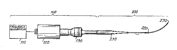
FIG. 1 is an elevated side view of an ultrasound
apparatus in accordance with ths present invention:
FIG. 2 i~ an elevated side view of a unitary microtip
and wire transmission me~ber lathed ~rom a single bar;
FIG. 3 is an elevated side view of a joint connecting a
microtip and wire transmission member; and
FIG. 4 is an elevated side view o~ an ultrasound
apparatus according to th~ invention which i9 adapted for
percutaneous insartion of at least a portion o~ the transmission
member into a patient.
.. . .. .
. . :
: ; :; ' :
13254~8 ~
DESCRIPT~ON_OF THE PREFERRED EMBODIMENTS
FXG. 1 depicts an ultrasound apparatus constructed in
accordanca with the present invention. From left to right are
shown an ultrasonic power generator 100 including a frequency
generator 110, a piezoelectric transducer converter 120 and a
horn 130. The power generator lOo, and/or parts thereof, may be
conventional. Additionally, an ultraRonic transmission member
200 removably attached to generator 100 include~ a microtip 210,
a wirs 220 and a distal end or tip 230.
The ultraconic power ~enerator 100 should preferably
have an operating frequency between approximate}y 10 kilohertz to
100 ~ilohertz, and most preferably about 20 kilohertz. However,
operating frequencies outside of thic rang~ may al90 ~e employad
in accordance with the invention.
Additionally, tha ultrasonic pewer generator 100
pre~erably has a variable duty cycle to facilitate generation of
pulsed ultra~ound. In accordanc~ with a preferred embodiment o~
the invention, the generator 110 should be capable o~ delivering
at least about 5 to 15 watts in output power.
A suitable ultrasound power g~nerator for use in
accordana~ with th~ invention i~ a Branson Sonifier Model 32SO
which operate~ at approximately 20 kilohertz for pulsed or
continuou~ ultra~ound.
Regarding the ultraqonic trans=ission member 200, th~
key paramater is the ul~rasonic attenuation coe~ficient (also
known as the ul~ra~onic damping or dampening ~actor) o~ the
matarial ~rom which it is constructed. Th~ material must have a
low coe~icient to be use~ul in accordancs with tha present
invention. Tha requirement that th~ transmis~ion memb~r 200 have
a low att~nuatlon coe~icien~ can alternatively bo expressed as
a r~quirsm~nt ror a high mechanical Q (quality ~actor).
In accordanG~ with th~ lnvention, tho transmission
-10--
~32~ 8
member is constructed of a metallic material. In 5electing the
metal o~ tho ultrasonic transmission member or wire, it should be
understood that all me~als convert some of their vibrational
energy into hea~t, resulting in an exponential attenuation o~ the
ultrasound and heating of the wire. The longer the wire, the
graater the loss and, consequently, the amount of heat generated.
At lengths of 50 cm, the losses in most metal wires are
sufficiently large that the wire will heat to the boiling point
of water, and only a small fraction o~ the input ~echanical
energy is transmitted~ This is clearly unacceptable.
The problem, then, is to find the right metal.
Neppiras investigated the Q'~ of various metal~, as part o~ a
general research program having nothing to do with angioplasty.
E. A. Neppiras, "Very High Energy Ultrasonics", British Journal
of Applisd Physics, Vol. II, April 1960, pp. 143-150. It has
baen found that the higher a metal'R Q, the less energy i5 lost
to heat when it vibrates and tho lower the ultrasonic attenuation
per unit length. The published results of Neppiras'
investigation ar~ as follows:
TABL~
_ _Mechanical
tool st~el 1,400
naval brass 3,000
K-Monel 5,300
aluminu~ bronze17,000
titaniu~ 24,000
duralumin~50,000
hiduminium>100,000
The mechanical Q o~ a partic~lar metal varie~ with
strain, ~requ~ncy, temp~rature, and other factorq. In N~ppira '
method, Q is mea3ured at F/~ and 20 KHz~ where F eguals thQ
~atigue stress o~ the metal in dynes/cm2 x 109. The value o~ Q
- . 132~4~8
is deduced from calorimetric measurement of energy dissipation.
I~ ha~ been found by the inventor~ that the absolute Q
value~ reported by Neppiraq can be used to broadly rank the
suitability of metals for efficient trans~ission o~ ultrasound
under angioplasty condition More particularly, the higher the
Q, the more efficiently the material transmit~ ultrasound in
accordanc~ with the invention. From Table I it therefore appears
that two alum$num alloys -- duralumin and hiduminium -- are more
likely to mora efficiently transmit ultrasc~und than the other
metals thera li~ted. (ThQ chemical composition of hiduminium is
very simllar to that of aluminum 7075, which is readily available
in bar form.)
Thu~, in a preferred embodim~nt o~ tho inventlon, the
hlgh-e~iciency ultrasound transmission membar i8 constructed of
a ~aterlal having a high mechanical Q value, pre~erably gre~ter
than about 50,000, and most prePerably greatar than about
100,000 a3 measured by the Neppira~ mathod at F~2 and 20 KHz.
In accordance with the invention, a material having a
high Q a~ measured by th~ Neppiras method at F/2 and 20 KHz will
be suitable for use in a high-ef~iciency ultrasound transmission
mem~er ov~r the entire range in frequency of operation o~ the
ultra~ound apparatus according to the invention.
Suitable materials o~ construction for th~ transmis~ion
me~ber include aluminum or aluminum-based alloy~ having tha
desired Q valus and which are pre erably utilized in their
annealed or Rtress-relieved ~tate. Indeed, it ha~ been ~ound
that aluminum-based alloy~ ar~ the mo~ pre~erred material~ for
the ultra~ound transmission member o~ the inven~ion. Pexsons
having ord inary skill in tha art will be abl~ to sclect
appropriat~ mat~rial~ of con~truction in accordance wlth th~
present di~clo~ure.
Th~ act o~ drawing wira to ~orm the transmi~sion member
-12-
:
,
,, ; ~
~` ~32~4~8
create imper~ections in the metal's polycrystalliné structu2e.
Thes~ imperfectiQns give the wire strength, but they also
increa ~ the ultrasonic attenuation due, it is currently
believed, to internal friction and hysterisis (the general theory
of damping due to these imper~ections is called "dislocation
dampingl'~. It is therefor~ pref~rred that the wire 220 not be
formed by drawing thereof but, rather, that the wire 220 and
microtip 210 b~ formed from a single bar or rod oP matarial which
i4 lathedO Whether the wire i5 drawn, or lathed ~rom a bar o~
material, however, it is most pre~erred that it be heat treated
to remove or reduc~ imperfectionq in the material and increas~
transmissio~ e~iciency.
Thus in a preferred ~m~o~iment o~ th~ invsntion, tho
aluminum ~or other metal) forming the wire should be in either
its annealed or a s~ress-relieved state. The stress-reli~ved
state is strongar than the annealed tate but has mcre
1mP2rfeCtiOng. HOWQV~r~ it ha been ~ound by the inventors that
both states work in accordance with th2 present invention. Thi
can be ac~ieved by h~at treating th~ wire in a manner known to
those of ordinary ~kill in th~ art of metallurgy.
Part~cularly pre erred aluminum-based alloys for
construct~ng thG transmission member according to the invention
ar~ A~-7075, A~-202~ and AL-6061. In this regard, titanium, with
a Q o~ only about 24,000, has be~n found by the inventor~ to have
ultrasound attenuation characteristics too great to be
satis~actorily us3~ul a~ tha material o~ constructlon o the
trans~isQio~ me~ber in accordanc~ with the present invention.
Preferably, the ultrasound transmission membar
comprises a wire having an ou~side dia~ter B o~ batwaen
approxi~ately 0.8 and 1.6 millimeter~. On~ snd o~ the wlrs i5
pr~ferably integral with the micro~ip which ~lareo into a one
hal~ inch diameter terminatio~ (identiriQd as dia~et~r "A" in
-13-
F
.
`:
^ ~ 323~8
FIG. 2) for attachment to the ultrasonic generator 100. This
flared siection is the acoustic "concentrator" which achieves the
impedance match between the wire and the generator. The
impedance match is achieved by eontrolling the taper o~ the
flar2d section, a~ i~ well known in the lit:erature. The
particular concentrator currently used, the Branson Microtip, is
a "conical sectional concentrator". However, other taper
profiles can also be used to achiev~ the impedance match. The
concentrator and ths wir~ are most pre~erably lathed from a
~ingls bar og metal so as to achieve a good match and to avoid
using drawn wiro. In accordance with the invention, the entir~
tran3mis~ion mamber i9i heat treated to either anneal or ~tress
relieve the metal.
The shape of the wire tip 230 has a ~trong influence on
system per~ormance. In accordance with the present inv~ntion, it
i9i preSerred that the wira tip be ~lat as it ha~ bean ~ound ~y
the inventorsi that a flat tip is sub~tantially more e~ective in
destroying plague than when the tip 230 i~ rounded or of
irregular shape as may result from cutting o~ the wire by a
conventional wiro cutter or pair of pliers. The peripheral edges
of the wir~ tip 230 may b~ smoothed or rounded so as to avoid
inadvartent per~oration or dama~e to tissue as the transmission
member i~i longltudinally advanced in, for example, an artery to
th~ intendQd internal site. However, at lea~t th~ remainder o~
the tip -- i. e. the facQ o~ th~ wlre tip 230 radially inward o~
th~ p~ripheral edge -- should, preferably, ba ~lat. It is
considered to b~ within th~ ability o~ on- having ordinary sikill
in tha i~rt to obtain a wire tip 230 which i~ ~lat.
Turning now to FIG. 2, a pre~erred smbodiment o~ a
unitary conn~ction or ~unction ~etwsQn th~ mlcrotip 210 and th~
wir~ 220 i~ illus~rated. In this e~bodiment, the microtip 210
and wire 220 are lathed ~rom a sinqle bar or rod o~ material~
-14-
:
,'~' ~, ,' ;
., .. . . . ~ .
. ~32~8
The microtip 210 according to thi~ preferxed embodiment is in the
ba ic form of a con~ ~ollowed by an exponential taper 211. It is
important that the junction between the microtip 210 and the wire
220 be constructed to enable the e~icient transmission o~
ultra~ound energy through the ~unction. While applicants have
found a unitary connection between the mi~rotip 210 and wire 220
to ba pre~erred, and the particular unitary structur~ illu~trated
in FIG. 2 to be highly satis~actory, it is contemplated that
other form~ of ~oints and joint structurQs may be employed in
accordance with the invention.
One such alternativa structur~ is illustrated, by way
o~ axample, in FIG. 3. As th~re shown, the microtlp 210'
include~ a bora de~ined therein and into which the proximal end
of the wiro 220' i~ inserted. Crushing ~orce is then applied to
the ~icrotip 2101, a~ indicated by the opposin~ arrow~ in FIG. 3,
to ~ecurely r~tai~ the end o~ tha w~ r~ 220' within th~ bor~O In
a ~oint o~ thl~ type it is preferable that the open end o~ the
bore 212' bQ curved or rounded.
Alternativ~ly, the bore in the microtip 210' may hav~ a
slightly s~aller diameter than th~ diameter of the wire 220'.
Upon heating o~ the ~icrotip 210', thQ bore will expand and tha
wiro 220' can b~ ins2rted th~rein: when the microtip 210' cool~,
the wir~ 220 ' will b~ held ~ Dly in place.
FIG. 4 depict~ the ultrasound apparatus according to
the inventlon adapted for percutaneous insertion of ths
ultrasound ~rans~ission member lnto a patient. As shown in FIG.
4, the wir~ 220 of the ultrasound tran~mission membr i~ disposed
withln a cath~ter 300 and positioned ~or applying ul~ra~onlc
energy to targ~ tissue 430 via the tip 230.
I~ this pr~ferred embodim~nt, thQ high-a~icisn~y
ultra~oni~ trans~i~sion member 200 and cath~ter 300, togQth~r,
ars adapt~d ~or p~rcutan~ou~ in~ertion into a pa~i~nt. In ~his
-15-
, , :
.
'~'
` ` ~32~4~8
regard, the wire 220 is located within the inner diameter o~ the
catheter 300 and is longitudinally relatively slidable
therewithLn back and forth along the length of th~ catheter 300
between a retracted position for insertion and an extended
position for opsrative use.
In th~ retracted position, the ti.p 230 o the wire 220
is either flush with or withdrawn inside the tip 310 of the
cathetQr 300 to avoid puncturing or otherwi.se damaging the
patient's artery and tissue during percutaneou~ insertion.
In the extended position, th~ tip 230 o~ th~ wir~ 200
i~ Qxtended sQveral millimeter~ out past the tip 310 of th~
catheter 300.
Pre~erably, the relative po~i~lon o~ the tip 230 o~
wire 220 with respect to the tip 310 of catheter 300 i3
indlcated by markings at least at or about the proxi~al end o~
wlre 220 -- that end o~ th~ wire closest to the microtip 210.
The sheath or catheter 300 may be of any appropriate
known ~orm. For US8 in a percutaneous insertion techniqu~, the
catheter 300 may pre~erably be constructed in full or part of a
matarial exhibiting relatively little resistance to passage
through th~ c1rculatory system of the patient and suitably
compatlblo with blood. Preferably, the catheter 300 i5
constructed o~ polyethyleno or polyurethane. Most prefera~ly,
tha cath~tar 300 is constructed of or coated with
polytetra~louro~thylene (Te~lon~.
It i9 ~urther conte~plated tha~ th~ catheter 300
employed ln the apparatus according to th~ inve~tion may
optionally includ~ an irrigation channel or space between the
wire 220 and tha insid~ diameter o~ the cath~ter for contrast
m~dia in~actions ~nd/or lubrication o~ ~he wir~ 220. It i3 ~1 o
cont~mplated that an in~ravascular anchoring balloon to a~ist in
holding th~ wire 220 in plac~ dur~ng u~ may be lncorporated at
-16-
, ~ , . :- : '''
,
1325~8
or near the tip 310 of catheter 300. In this regard, a three-
foil balloon that will not appreciably obstruct blood flow is
preferred.
The operation of the ultrasound apparatus according to
the invention will now be described.
Referring once again to FIG. 4, the catheter 300 is
inserted into the patient using a standard percutaneous insertion
technique well known in the art. The wire 220 is then inserted
into the catheter 300 and advanced until the wire tip 230 is
within several millimeters of the catheter tip 310. Once the
catheter tip 310 is positioned close to the obstruction or target
tissue 430 in the patient's artery 420, the wire is advanced to
extend the wire tip 230 several millimeters beyond the tip 310 o~
the catheter 300. Once so positioned, ultrasonic energy,
preferably pulsed ultrasound, is applied via the tip 230 to the
obstruction or target tissue 430 at an intensity and for a
duration sufficient to substantially break up the target tissue
~30 and recanalize the patient's artery to restore good blood
flow therethrough.
Additionally, it is contemplated that the apparatus
according to the invention be used to generate ultrasound
contrast medium in situ for ultrasound echo imaging to monitor
the progress and success oE the ultrasound treatment in breaking
up the target tissue 430. In this regard, during transmission o~
ultrasound energy, ultrasonic vibrations at the tip 230 of the
ultrasound transmission member 200 generate microbubbles in the
patient's bloodstream. These microbubbles are visualized by
conventional ultrasound echo imaging systems wherein the
microbubbles appear as a contrast medium. Those skilled in the
art will recognize and appreciate the significant advantages
realized in this manner bv obviating any need to inject, as is
conventional, a separate contrast med^ium into the blooclstream of
the patient for X-ray imaging.
-17-
lL32~4~8
. .
Following treatme~t of the target tissue 430, the
ultrasound apparatus is withdrawn.
The following examples will further illustrate, hy way
of example, the invention.
Methods
Ultrasonic an~io~lasty catheter
The apparatus employed for the following experiments
comprised a flexible ultrasonic transmission wire housed in a No.
5F Teflon sheath wherein the wire was freely advanceable and
retractable. Markings on the wire indicated its position
relative to tha sheath. The proximal end of the wire was
attached to the ultrasonic power source (Branson Sonifier, Model
B250) which was capable of generating 20khz pulses or continuous
ultrasound; the front panel settings of the Sonifier were set at
30~ duty cycle with a power setting of 1 to 2 for all
experiments. Wire diameters of 1.0 mm and 1.6 mm and lengths of
12.5 cm, 25 cm, and 37.5 cm were employed.
Testing in vitro
Atherosclerotic plaque disruption: 31 aortic sections
were removed from individuals who underwent postmortem
examination within 24 hours of death and stored for less than 24
hours in 0.9% saline solution a-t a temperature of 4 degrees
centigrade. The segments represented the full spectrum oE gross
appearance from normal through soft raised atherosclerotic
lesions to complex lesions. The tip of the ultrasonic catheter
-- i.e. the ultrasonic energy-carrying wire -- was placed in
direct contact with eacll of 25 sections containing
atherosclerotic plaques. Power was applied while the wire tip
was swept over the entire area of the plaque until gross
observation indicated that the plaque had either been en-tirely
removed or had ceased to decrease in size. During application of
-18-
~r
,~
1325~
ultrasound, the contact area was continuously irrigated with
saline 301ution. Runoff was collected and examined
microacoplcally using polarized light and contrast phase
microscopy. Six healthy human aortic secti.ons were exposed to
ultrasound for l20 to 240 seconds.
All aortic segments exposed to ultrasound were placed
in 10% neutral fonmalin. After fixation, two millim~ter thick
serial cross-sections of the aortic wall w~re embedded in
para~fin and five micron thick ssGtions were stain~d with eosin
and hema~oxylin, or with alastin.
Ultrasonic thrombolysi~: Thrombus was ~or~ed by
allowing 2.5 ml blood to stand ~or 4 to 6 hour~ in a test tube.
5 control and 5 test thrombi were studied. The wire tip wa~
brought into contact with the thrombus and slight pre~sure wa~
applied to penetrate the sur~ace. In the test group, ultrasonic
power wa~ then applied ~or 20 to 30 second~, durlng which time
the wir~ was advanced through the thrombu. 2 to 3 times. In th~
control gro~p, no power wa~ applied while the wire was advanc~d
throu~h the thro~bu~ 2 to 3 times. Each thrombus, both control
and tQst, was th~n centrlfuged for 3 minutes at 2000 rpm and ths
liquid ~up~rnatant wa~ separated from th~ resldual solid
thro~bu~. Thrombus wa~ weighed be~ore and aft~r treatment. The
liquid suparnatant was microscopically examined.
11 mongr~l dog~ weighing 20 to 35 kg wer~ studied.
Tho dogs w~re divided into two groups on tha basi~ o~ the
monitoring ~guipment used- 4 dog3 w~re hemodynamically
monitorsd, whilo 7 dogs wera studiad angiographically.
Hemodynamically monitored group: G~neral anesth~ ia
wa~ inducQd by ph~obarbi~al. Ar~er surgical expo~ur~ o~ both
fe~oral art~ri~3, direct pre~sur~ traclng~ w~r~ obtain~d from
each artery di~tal to tho sit~ o~ int~nd~d occlusiQn~ ~hrombus
i. '
1 . '
~ ' ,
132~8
was generated. The right femoral artery wa used as test; a 3 to
4 cm length of intimal injury was achieved by balloon de-
endothilizat~on and crushing with forcep~. The proximal and
distal ends o~ the injured segment wera then temporarily ligated
and thrombln was injected lnto the occluded segment. The trapped
blood was allowed to clot for 90 to 120 minutes. The tie~ were
then released and vessel occlusion was a~certained by reduced
pulse pressure a~p}itud~ in the tracing. rh~ left ~emoral artery
was left unoccluded as a control.
Angiography group: 11 femoral arteri~ 7 test and
4 control -- wer~ occluded as describQd above. A~ter liyatlon,
stainl~s~ stael needl~ were inserted into th~ -~urrounding ti~sue
at th~ ligation 3ites to serve as va~cular markers that d~inod
th~ extent of endothelial iniury and occlusion during
catheterization. After tho ties were releasQd, vessel occlusion
was ascertained by hand in~ection~ o~ contrast material with 35
m~ cin~ filming.
Ultrasonic thromboly~is protocol in vivo
Angiography group: After occlusion was verified
angioqraphically! the ultraRonic angioplasty wire was introduoed
into the ~xpos~d e~oral artery, approximately 15 to 20 cm distal
to the occlu~ion. The wire wa~ advanced to th~ site of
occlusion and then Sorc~d 1-2 c~ past the first vai~cular marker.
Pul~ed ultra~ound was then applied for 2 minute~, during which
time th~ wir~ tip was passed betwesn th~ vascular marXers 1 to 2
t~mes. Ultra~ound was applied only whil~ thQ tip was betwaen the
two vascu}ar ~arX~rs. After application of ultraRound,
recanalization was ascertained through in;ection o~ contraat
media. In the control arterie~, mechanical bridging o~ tho
occlu~ion was att~mpt~d. ~h~ ~ire tip, with ultra~onic pOWQX
turned e~, was ad~nced into ~he sit~ o~ occlu~ion and remained
ther~ ~or 2 minl~tes, during which tim~ it wa~ pa~s~d back and
-20-
,- ,
. ~ :
,
- 1325~
forth between the vascular markers l to 2 times. Angiographic
study was then repeated. Ul~rasonic transmission wire diameter
was 1.0 m~ in one test vess~l and onQ control vessel; all other
experiment~ were conducted with 1.6 mm diamater wire. All
cineangtograms were judged by two reviewer$ and were classified
as:
l. total recanalization - res~oration o~ ~ 75~ o~ lumen
dlamet~r;
2. succ~s~ful recanallzation - reduction o~ obstruction by
m~rQ than 25~; or
3. unsuccessful recanalization - no change ~rom baseline.
~ emodynamic group: Onc~ obstruction was veri~i~d by
blood pressur~ tracing, introduction o~ the ultrasonlc
angiopla~ty wire into the ~emoral artery was per~orm~d a~ above.
Mechanical ~ridging wa~ attemptad on the occluded right artery.
The wlr~ tip, with th~ ultrasonic pOWQr to the wire turned orf,
was advanced inko the site o~ occlusion and remained thera for 2
minut~, during which tima it was passed back and forth betw~en
the vascular markers l to 2 times. The wire wa withdrawn and
blood pressure tracing recorded. The wire was then read~anced
into tho slte and pulsed ultrasound applied for l ~inute. The
wiro wa~ wlthdrawn and blood pres~ure tracing wa~ recorded. The
ultrasound ~ppllcation cycle wa then repeated.
Succ~sPul r~canalization in the test artery was
de~ined a~ a restoration o~ blood pres3ure to 50~ o~ blood
pras~ure in tha control artery~
In both groups, the animal wa~ sacrificed immediat~ly.
Te~t and control arterial se~ment~ wer0 removed and placad in 10S
neutral ~ormalin, After ~ixation, two millimqt~r thick s~rial
cro~s-s~ction3 Or the art~rial wall wQr~ smb~dded i~ para~in and
~ive ~icron thlck section~ wara st~in~d w1th ~09in and
hematoxylin.
~:
~325~8
Result~
In vitro ul~sonic ~laque_disruPtion
25 athero~clerotic plaque~ wer~ exposed to the
ultrasonic angioplas~y catheter. On gro3~ ob~erYation, th~
plaque-bearing spacimens showed dissolutiorl o~ plaque with either
total removal o~ plaque or crater formation within ths plaque.
There was variation in the rate at which pl.aquo~ were disrupted.
Soft fatty plaque~ dissolved most rapidly, while h~avily
calcified plaque~ were the most resistant to ultrasonic
disruption. No gross damagQ wa~ observed to healthy or normal
tissus ~ither underlying or adjacent to th~ plaqu~. Histological
axaminati~n o~ s~ction showed n~ recognizabl~ athorosclerotic
plaqus structura remaining. Residual plaque material was noted.
The cellular architecture in the tlssue ad~acont to tlle araa of
ultrasound application remained intact. Runo~ analy~is ~howed
t~e debris to bo mainly cholesteroI crystals and necrotic tissue
remnants. Th~ cholesterol crystals rangad i~ siza from 10 to 80
micron~ in diamet~r; ~0% o~ tha crystal~ wer~ less than 10
micron~. TissuQ r~mnants ranged in SiZQ ~rom 50 to several
hundred ~icrons i~ diameter. Histological examination of tha six
healthy sQg~nts ~xposed to ultrasound showed no damage to the
media or advsntl~ia.
~
~ hromboly~is by th~ ultra~onic angioplasty catheter
redu ~d solid thrombus weight ~ro~ 1.56 1 0.15 gr (+ 1 S.D.) to
0.35 + 0.Q8 gr, while solid ~hrombu~ welght in thQ control group
was r~duc~d ~rom 1.50 ~ 0.09 gr to 1.26 ~ 0.12 gr: av3rage
percent roduction in th~ test group wa~ 76.9 + 5.1% as compared
to 15.8 + 5.8% in thQ control group (p ~ 0.0001, n-5, student~ t
test). Micro~opic exa~ination of th~ liquid supernatant show~d
1 to 5 Sibrin ~ragment~ p~r high pow~r ~ield. No r~-s:oagu}atior~
oi~ the liquid ~upernatant wa~ noted a~ter 60 minutas.
--22--
.
.
~ . .
, . .
r~ 132~i4~8
In vivo thrombolysis
Angio~raphv ~rou~- Ultrasonic thrombolysis was
attempted on test vessels with complata (n=4) or subtotal ~n=3)
occlusion~. An additional 4 occluded vess~els with co~plete (n-l)
or subtotal ~n-3) occlusion served as control. According to the
recanalization criteria, 7 out of 7 test v~essels were totally
recanalized using the ultrasonic angioplasty catheter. Attempted
bridging o~ thrombotic occlusion$ via mechanical penetration in 5
control vessel achieved ~otal recanalization in no vess~ls, and
success~ul recanalization in 1 vessel. 1 control vessel wa
mechanically per~orated during attempted bridging. In the
succe3sfully mechanically recanalized v~ssQl, a sacond channel
through the partially occlugLvQ thrombu~ was created by
mechanlcal penetration; this channel decreased the obstruction by
30% to 40%.
Hemodyna~icallY monitored a~oup: In 3 o~ 4 te~
arterie~ successful recanalization wa~ achieved after applicatlon
oS ultrasound, according to recanalization criterion.
stoloay
Histolo~ical studies were carried out on 7 o~ the
canine tast z~t~rial 3~gments ~xposed to ultrasound in vivo and
on 4 control canine arterial segments. In all sections examin~d,
both t~st and control, damage to the intima and media was
obs~rved, while the adventitia appe~red undamaged. Section~
exposed to ultrasound did not show any greater histological
damage than did the con~rol sections. Intraluminal ~hrombi were
present in all seg~Qnts; test and control showed no diff~renc~ in
the extent o~ intra}uminal thro~bosi~.
T~ ultrasonic angioplasty catheter according to the
inv~ntlon has proven to e~rectiv~ly induc~ ~hrombolysi In
vivo, the ultra-Qonic angioplasty cathetar achi~v2d total
angiographic recanalization in 7 of ~ partially or completQly
-23-
;, :
`
.
1325~58
thrombotioally occluded canin~ femoral arterial segments.
Furthe~more, hemodynamic monitoring in an additional 4 dogs has
shown ultra~onic angioplasty catheter to restore blood pressur~
in 3 out o 4 thrombotically occluded femoral arterie~. ~ttempts
to recanalize by purely mechanical penetration of thrombotic
occlusion (using the wir~ with no ultrasonia power applied
thereto) were unsuccessful, indicating that recanalization was
primarily duQ to the effect of the ultrasound and not due to the
m~chanical pen~tration o~ the wire into the thrombua.
~istologic studie~ showed intimal and medial damage in both the
t~t and control canln~ arteries: there was no adv~ntitial
da~ag~. That thQ t~st sections ~xposed to ultra~ound showed no
more da~age than the control sections indicate~ th~t the intimal
and medial damage observed may have been due to the in~ury caused
by de-endolithization and crushing wlth forcep3 to induce
thrombo~is. In vitro, thromboly~is induc~d by the ultrasonic
angiopla~ty catheter produced abundant ~ibrin fragmentR in th~
liqui~ied portion o the thrombus, while reducing eolid thrombu~
weight by 77~ on average. The ultrasonic angioplasty cathet~r of
th~ invention thu~ achieved e~ective in vivo thrombolycis with
mini~al damago to ad~cent vascular tissue, pr~sumably through
selectiv~ ds~truction o~ the fibrin matrix in the thrombu~.
Th~ ultrasonic angioplasty catheter effectively
di~rupted 25 human atherosclerotic plaques. Fatty plaques wer~
found to b~ the most sensitive to ultrasonic destructio~, while
heavily calci~ied plaques wer~ ~he most resistant. Gros~
inspection a~ well a~ microscopic examination did not reveal
damag~ to th~ vascular tissue underneath or ad;acent tQ ths area
o~ expo3ure. Long ~xposures o~ heal~hy arterial wall segme~ts to
the ulkra~onic angiopla~ty catheter o~ ~he invention did not
produc~ hi3tological damage.
Tho ultrasonic apparatus according to the inV~ntiQn
-24-
.
~ 132~8
destroys both plaques and thrombi while leaving healthy vascular
tissue undamaged. Experience indicates that this selective
de truction makes it user-friendly: there i3 no need for highly
~recise applica ion of pow~r ~ince misdirection o~ the ul~rasonic
energy carrying wire does not result in damage to the healthy
arterial wall. The potential advantage that ultras~nic
angioplasty offers over alternative systems is that ultrasound
exploit~ the inherent phy~ical dif~erencs between the healthy
arterial wall and the obstructiv~ plaqu~-thrombus complex,
allowing fox selective destruction o~ only th~ luminal
obstruction with no damage to ths mechanical integrity of the
ve~s~l .
It should of courso be understood that the foregoing
examples are presented solely by way Or example to lllustrate the
operation, uss and advantageou~ bene~lts reallzable in accordance
with tha present inventlon, and are not intended to serv~ as a
limitation, ~ither expreq~ or implied, on thQ apparatuc or tha
methodts) o , or a~ to the ~copa of protection to be accorded,
the Lnvention. Thus, whil~ therQ have been shown and described
and pointcd out fundamental novel f~atures o~ the invention as
applied to pro~erred embodimentq thereof, it will he recognized
and ~u t be under~tood that variou omissions and sub titutions
and chang~s in th~ ~orm and detail~ of the devices illustrated,
and in their u Q and operatlon, may be mads by thos~ skLlled in
th~ art without departing from the spirit o the invention. It
is the intention, therefore, ~o be limited only as indicated by
the scope o4 the claim~ appended hereto.
-25-
.
.