Note: Descriptions are shown in the official language in which they were submitted.
~32~569
XF74
BAG INCI.llDING A FI LTER
'
'~ This invention relates to a bag or pouch
including a filter and for receiving discharge
from the human body. Examples of such bags or
pouches are ostomy pouches and wound drainage bags.
The prior art is replete with designs of
filter and with proposals for their inclucion in
' 10 an o~tomy bag, all directed at the problem of
;~ allowing e~cape of flatus gases from the bag while
removing noxious smelling components from such
ga~es. Examples of proposals can be seen in U.K.
~i Paten~ Nos. 1 117 204, 1 405 032, 1 462 492, 1 595
047, 1 595 906, 1 596 496, 2 036 564 and 2 059 797
and Canadian Patent 631 987, but there are many
others. It ha~ proved difficult to meet the
important reguirement of good filtering
efficiency, comfort in wear, and minimum filter
thioknes~. It will be appreciated that as an
f o~to~y bag i8 worn under clothing, the bag plU8
~,~ filter de~irably should he unobtrusive. Comfort
in wear firstly requires flexibility of the filter
as well a~ the bag and it is also desirable that
the filter parts should be spaced from the tender
~ 6tomal region. The present invention aims to
:~, solv~ or at lçast greatly mitigate these problems.
The present appl1cant has suggested in U.K.
Patent No. 2 139 501 B that an o~tomy bag
.. ~,.. : . . . - , . ~ : ~ , . .
13 25 ~ 69 XF74
particula~ly for lleostomy patients should be
constructed with an intervening wall divlding the
bag into two chambers. The present invention
improves upon this concept by providing an
intervening wall of a particularly advantageous
nature.
According to the present invention, a bag
or pouch for receiving discharge from the human
body is made of two superposed sheets of synthetic
plastics material joined around their edges and
has a filter attached to an upper part o an
interior surface of one of the walls, there being
a hole or slit in the wall to allow gases exiting
the filter to pass to the exterior of the bag or
pouch, and an intervening wall is included to
separate the filter region from the remainder of
the interior of the bag or pouch, said intervening
wall being characterized by having a series of
scatter holes therein, there being from 100 to 300
hole~ per square inch (155000 to 465000 holes per
square meter) and each hole having a maximum
dimen~ion of from 130 to 340 microns.
It has been surprisingly found that these
, value~ allow fully adeguat~ flow of gas from the -
bag interior to the filter region and yet do not
permit any substantial wetting of the filter, or
clogging of the filter by body exudations such as
fecal slurry.
It i8 preferred that each hole is
substantially circular, and that the holes should
be ~ub~tantially uniformly spaced over the whole
of the intervening wall.
The filter preferably (but not necessarily)
I includes the following component~ laminated -~
-, 35 together in the following order:
. .
~ I
~25~
XF74
(a) a layer of hot-melt adhesive whereby the
filter may be affixed to a wall of the bag
(b) a layer of microflne non-woven material;
(c) a matrix layer of hot melt adhesive;
(d) a filter member of carbon-impregnated
polyurethane open cell foi~m;
; (e~ a matrix layer of hot melt adhesive; and
(f) a layer of non-woven fabric.
The filter is, as stated, dispo~ed in the
10 space defined between the bag wall and the
intervening wall. Preferably, the bag wall has an
S-Rhaped cut therein to allow exit of flatus
ga~es, located substantially at a central region
of ths filter. The intervening wall in use serves
to permit the passage of flatus gases from bag
interior to filter but substantially prevent
passage of liquids or solids.
A6 an alternative, any suitable filter may
be u~ed.
The layer of non-woven fabric in the
preferred filter has an air permeability in the
range 0.25-1.0 c.c./ cm~ 2/sec at 10 nul~ W.P.G.,
and ha~ a weight of 64 gm/m2 plu~ or minu~ 10%. :::
Th~ xe~ultinq laminated filter a~sembly ha~ been
found to have excellent deodorizing properties as
wall a~ high transmissibility to gas. In an H2S
deodorization test, a fully sati~factory
d~odorization was achieved with a flow of over 9
liters in 45 minutes.
The invention will be better understood
from the following description of a particular
embodiment thereof, given with references to the
accompanying illu~trative and non-limiting
drawings, in which:
.
~ .
.; ...... .,: ...... , . i .:. .: . .. , .. . . . - ; .-: . . , .. . ( , .. : ., ,: . . . .. . : .. .. .
1325~9
XF74
-4-
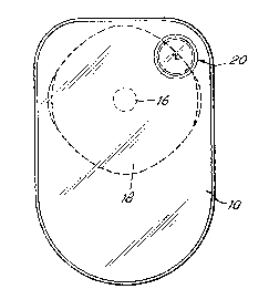
Figure 1 is a front view of one embodiment
of an ostomy bag according to the lnvention;
Figure 2 is a rear view 5i.e, looklng
directly at the body-side of the bag) of the bag
: 5 shown in Figure 1;
Fisure 3 is a diagrammatic cross-section of
the bag shown in Figures 1 and 2;
Figure 4 is a cross-section through part o
the non-body side wall of the ostomy bag shown in
Figures 1-3, illustrating the filter and the
intervening wall; and
Figure 5 is an enlarged cross-sectional
view of the ilter showing its laminated ::
construction.
Referring firstly to Figures 1 to 3 the
illustrated oistomy bag is largely conventional and ~ :
comprises front and rear panels 10, 12 of
synthetic pla~tics material joined around their
edge by any ~uitable plastics welding or joining
technique to constitute an ostomy bag. In
addition, to give comfort and a warm feel to the ~ ~:
skin, a needled fil~ 14 overlays the rear bag
wall. A stomal orifice 16 (Figure 2~ extend~
1. through the needled film and the rear bag wall and
;, 25 a pad 18 of medical grad~ adhesive, having thereon
, a poly~thylene layer, is included so th~t the
ostomy bag can be stuck to the body of the wearer
I in conventional manner. The adhesive surface of
-~ this medical grade pad is exposed by pulling off a: : :
protective layer of release paper. Suitable
medical grade adhe~ive compo~itions are pressure
¦ sen~itive adhesive formulations that consi~t of a
I homogenoui~ blend of one or more water soluble or
! water swellable hydrocolloids dispersed in a
.¦ 35 viscous elastomeric substance such as
¦ polyi~obutylene a8 disclosed by Chen in U.S.
~3~5$~
XF74
--5~
Patent 3,339,546. Opt1onally, the adhesi~e
composition can al50 include one or more cohesive
streng~hening agents as described by Chen et al. in
U.S. Patent 4,192,785 or one or more hydrat~ble
5 natural or synthetic polymers as described by
: Pawelchak et al. in U.S. Patent 4,393,080.
Pre~erably, the adhesive pad include~ a thsin water
: insoluable polymeric film s~lch as polyethylene.
A~ will be seen in Figuxes 1 and 2 a filter
10 as~embly 20 i~ located at an upper corner of the
: bag and the bag wall 10 has therein an S-shap~d
cut located ~ub~tantially centrally o~ the filter
a~e~hly 20.
Referring now to Figures 4 and 5, although
15 the filter a~embly i~ seen a~ circular in the~e ~ .
Figure~, clearly thi~ i~ not essential. It could ::~
b~ oval or roctangular or any other convenient
shape. The illustrat~d filter assembly includes
s the following layer~, and is attached to th~
20 in~id~ surface of the bag front wall 10. The
lay~r~ aro li~ted in the order moving fro~ the baq
wall toward~ ~h~ interior of the bag, and compri~e:
(a) a l~yar 200 of hot melt adh~sivo whereby
thc filter may be affixed to the wall of
. the b~g;
(b) a layor 202 of microfine non-woven
~at-rial; Trado-Mark LUTROV~L 708 i~
particularly ~uitable;
(c) a matrix layer 204 of hot m-lt adhe~ive;
(d) a filtar disc 206, preferably 2 m~ thick,
: of carbon-i~spregnated crushed polyurethane
open co~l foam;
(~) a matrix lay~r ~08 of hot melt adhsesive and
(f) a layar 210 of non-woven fabric.
~, ,
~ r -~,
,..
~32~56~
-6- XF74
~ ot connected to the filter, but connected
to the bag wall by a closed loop weld entirely
surrounding the filter, is an intervening wall
30. This is preferably made of EBA (ethylene
butylacrylate) synthietic plastics material 50
microns thick, needled at about 160 holes per
square inch, that is, about 24B000 holes per
square meter. One may employ from about 155000 to
465000 holes per square meter (100 to 300 holes
per sqyiare inch) or, more preferably, from about
186000 to 310000 holes per square meter (120 to
200 holes per square inch). The holes are
preferably su~stantially circular, though this is
not absolutely esse~tial. The maxlmum dime~sion
o~ each hole may be from 75 to 300 microns, ~ -
pre~erably 100 to 250 microns, and more preferably
110 to 240 microns. The purpose of the intervening
wall 30 is to permit gas flow therethrough but
sub~tantially prevent any liquid or solid bag
content~ coming into contact with the filter.
The ~ayers 202-210 specified above are
integrated into a filter assembly by heat and
q pressure, following which the filter assembly is
attached to thie interior surface of the bag wall -
by ~uitably activating, by heating thie adhesive
layer 200. One suitable material for thie layer
202 is a polypropylene microfine non-woven film.
A suitable ~ilm of this type is known under the
Trado Name LUTROVIL 708. A suitable material for
the layer 210 i8 a ga~-permeable non-woven
I ~ynthetic plastics material known by a
manufacturer'~ designation V115/463.
By adopting this design, a satisfactory
filter 8ecurely attached within an ostomy bag can
b~ provided, the overall thicknesc of the bag in
th~ filter region being well under 2 1/2 mmi.
1 3 ~
_7_ XF74
Moreover, both filter and bag are flexible and are
unobtrusive even when worn under thin clothing.
The bag and filter are also flexible and tend to
follow the contours of the wearer's body.
As an advantageous fe ture to enha~ce the
overall fle~ibility of the bag, the backing film
on the medical grade adhesive is preferably
embo~sed polyethylene. A film embossed with
grooves is particularly preferred. A groove
height and width o the order of around one-tenth
of a milllm~ter may be employed.
Another advantag~ous feature of the
- illustrated design is ~hat the medical grade
adhesive may have thereon a sheet of paper
carrying dimensioned circles as a guidance for the
u~er when cutting a stomal orifice of the appropri-
ate diameter in the medical qrade adhesive pad.
The adhesive i8 covered with a layer of release
paper. The release paper i8 made to project
slightly beyond the medical grade adhesive at regions
located, for exa~ple, at the two ends of a horizon~al
dia~eter, ~uch projection being for example about 2
. or 3 mm. beyond the adhesi~e. These projections
form an ea~ily gripped tab to facilitate the peeling
off of th~ release sheet carrying the stomal diameter
di~gram~ once th~ nece~sary hole ha~ been cut by
3ciEsor~ by the wearer in the conventional na~ner.
,'
' ': '
'~ ' ' "
'