Note: Descriptions are shown in the official language in which they were submitted.
132~46
-- 1 --
The Method and the Means for Removinq Ice from a Ship's Channel
This invention concerns the method and the means for
removing ice from a channel opened in the ice, or from around a
ship stuck in the ice, thus releasing it.
When a ship moves in a channel opened in solid ice, it
pushes part of the ice accumulated in the channel underneath the
solid ice beside the channel. During the winter, relatively deep
ice ridges formed of ice blocks frozen together, form beside the
channel. When the ridges are so deep that the ice pieces pushed
aside by the ship cannot pass under them, the ice pieces stay in
the channel, filling it and making it difficult to navigate.
~his invention is intended to create a method for diverting
the ice pieces under the ice, far enough outside the side ridges,
so that the channel can be kept navigable throughout the winter.
In accordance with an embodiment of the present invention
there is provided a method for removing ice from a ship's channel
by an icegoing ship having at least one main propeller positioned
between sides of the channel, comprising adjustably turning the
at least one main propeller for turning a stream created by the
at least one main propeller upwards in the direction of ice
pieces so as to push the ice pieces away~from the ship's channel
and under the ice adjacent the ship's channel.
In accordance with another embodiment of the present inven-
tion there is provided a device for removing ice from a ship's
channel, comprising means for directing at least one propeller
stream adjustably upwardly toward ice, the at least one propeller
stream being produced by at least one main propeller of an ice-
going ship.
In accordance with a still further embodiment of the present
invention there is provided a device for removing ice from a
ship's channel, comprising means for directing propeller streams
adjustably upwardly toward ice, the propeller streams produced
by main propellers of an icegoing ship, the propeller streams
being directed upwardly and prevented from spreading downwardly
13257D~6
- la -
by a foil arrangement.
This invention is characterized by the use of the propeller
stream for pushing the ice away. The propeller stream is turned
either up to the surface or both up and to the sides. The turn-
ing up is best performed by leading air or another gas into the
propeller stream. The most suitable gas is air, and it is
normally led through the outlet points behind the propeller.
Thus it does not reduce the propeller thrust or the motion energy
of the propeller stream. In a situation where it is required to
reduce resistance, air is led temporarily to the front of the
propeller, according to Canadian Patent Application No. 520,768,
filed October 17, 1986.
When led to the propeller stream, air is mixed with water
by the eddies in the stream. The propeller stream, when it
contains air, is lighter than the surrounding water. Hence it
rises up to the surface where it spreads to the sides pushing the
ice mass away from the channel.
In prior art, it is known to use ice ploughs positioned
under the ship bottom, and ship bottom forms designed for
clearing the channel, increase the resistance of the vessel also
when moving in open water. They neither do have any effect on
the ice beside the ship.
:- . , , . : : , . ~ . ~: .
'~.. ' . ,' ~ . ' .
~ 2- 132~7~
In prior art known devices for clearing the channel, and
both the water jet and air blowing devices made for removing
ice from the hull of the ship, have little power because
almost all machine power is needed for the propellers when
navigating through the ice. Propeller streams have been
used to release a ship stuck in the ice, but their impact
has not had a wide radius, because the stream spreads down
an to the sides so rapidly.
This invention is characterized by the fact that the whole
power of the propeller stream is used and the stream is
turned up towards the surface where the ice is situated.
So the force of the stream will reach a wider radius.
A very small part of the total power, about 1-2 %, in any
case over 0,5 % and below 5 % of the machine s power, is
enough for the blowing of air.
One possible use of this invention can be seen in the case
of an icebreaker helping a slow convoy and it can use its
whole engine power at full effect and continuously. If the
ships in need of assistance are left behind, the icebreaker
blowing air into the propeller streams will turn its rudders
to plough so that its own speed will be slowed down and the
channel will be cleared wider. Hence the ships in need of
assistance can navigate even without towing. The icebreaker
will adjust the angle of ploughing to keep the ships at the
correct distance.
This lnvention is further characterized by the fact that the
propeller streams made by the full power of the main
propellers are used to transfer the ice. The energy of
these propeller streams is multiple compared to the stream
made only by air or other stream systems. To turn the
propeller stream up, for instance by mixing it with
air and so making it lighter, needs only a small part of
the machine power, about 1 %. A water stream containing
air keeps its tendency to turn up also on the other side of
the solid side ridge, so that its influence on the movement
of loose ice under the solid ice is widely spread, even
behind barriers.
This method is primarily suited to solid ice areas, in
gulfs, in archipelago channels, and in lake and river
,
,
- , ' -~ ' ' '
.
- 3 ~ 132~7~
navigation. By using this method the channel broken in
solid ice is cleared of the ice blocks.
An additional advantage of this method is the fact that the
quality of the water which is at its poorest during the
winter under the ice, containing as it does very little
oxygen, can be improved by aerating. Because oxygen is
diluted more easily into ice cold water than warm water,
and because the ice cover prevents air from escaping, the
aerating can succeed in winter. Moreover, the air trapped
under the ice will act as insulation and will therefore slow
down the thickening of the ice. Also the bubbles frozen
into the ice will make it weaker.
Tests have shown that blowing air into the ship s propeller
stream when reversing will remove ice from around the ship
and will make it easier to loosen the ship if it has been
stuck in the ice, or has frozen solid during anchoring or
whilst being fastened to a pier. A ship in a difficult
situation, which has to move alternately by backing to make
speed, and by ramming, will open an open water area around
it for making speed by directing air continuously into the
propeller stream. When reversing the air is blown through
the outlets in the front of the propeller.
The invention and its details will be explained more closely
as follows with references to the accompanying drawings,
wherein
Figure 1 is a side view of a ship stern where the invention
is applied,
Figure 2 is a rear view of a two propeller stern with
inclined rudders, of which the one on the right is turned,
Figure 3 is a rear view of a ship stern with two rudder
propellers with nozzles, of which the one on the right is
turned,
Figure 4 shows side and top views of an icegoing ship and
propeller streams turned up by air blowing,
Figure 5 is a bottom view of a two propeller icebreaking
ship with propeller streams mixed with air and the rudders
turned to a ploughing position.
4~ 2 ~ 7 ~ ~
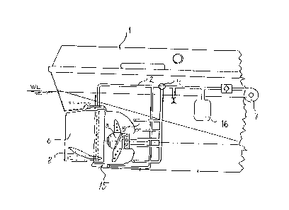
In the embodiment of Figure 1 there is in the rear part
of the ship (1) a pipe system (2) in order to pass air
to the front and to the rear of the propeller (3). The
pipe system is provided with a valve (4) in order to
lead air either to the rear or to the front of the
propeller. The pipes leading air behind the propeller
are opened at the front edge of the rudder (6) and to the
top surface of the sole piece (15). When reversing,
pipes leading air to the front of the propeller are opened
at the rear face of the sternpost (5) and at the propeller.
For the supply of the air into the pipe system, the pipe
system is provided with a fan (7) or with a compressor.
The system may also be provided with a compressed air
tank (16). The propeller is located completely below the
water level WL. When the ship runs forwards and the
resistance to rotation of the propeller must be lowered
because of ice, air is passed to the front of the propeller,
its suction side. At the lower edge of the rudder (6) there
is a foil (8) to lift the propeller stream up. In this
picture the rear part of the foil is turnable and the front
part is fixed. Air is also led to the lower part of the
propeller stream through this foil.
Figure 2 shows a solution where the rudders (9, 10) are
in an inclined position, so that the rudders when turned
outwards, as in Figure 2 the right one (10) is, lift the
rudder stream to the surface. At the lower edges of the
rudders there are fixed foils (8) preventing stream from
spreading downwards. The propeller stream without air,
when hitting a solid ice ridge, is turned downwards, but
the lightening influence of air will lift the stream
behind the ridge up again to the lower surface of the solid
ice to move loose pieces of ice (12) further away.
Figure 3 shows a solution with rudder propellers (13) with
nozzles which are also inclined so that the propeller
stream when turned outwards will rise to the surface.
Figure 4 illustrates how the propeller stream, lifted up
by air bubbles (14) when running forward, is diverted to
the surface at the elliptical area (15) behind the ship.
Arrows (16) show the flow at the surface away from the
channel. Fieure 4 also shows how the propeller stream of
- , ~. , - .:
.,: ' ~'' '' : `
5. l~ `2~ 7 ~ 6
a reversing propeller is lifted by the air to the surface
around the ship, and is turning at the surface according
to the arrows (17) away from the ship. The rudder post ~18)
of the rudder (6) is inclined so that the upper end is
further behind. When the rudder is turned to the side
it will lift the propeller stream pushing it up towards the
surface.
Figure 5 shows an icebreaker with two propellers, from
below, breaking the ice and clearing the channel. The
rudders (6) have been turned to plough. The propeller
streams are lifted either by inclined rudders or by air
mixed in the propeller stream, to the under surface of the
solid ice in the areas (15). The loose pieces of ice (12)
from the sides of the ship are transferred by the propeller
streams to an area (19) at a distance from the channel (20).
The figure also shows the rudders (21) in front of the
propellers (3). When reversing these can turn the propeller
streams to the sides, where air will lift the propeller
streams up to the surface, or if these rudders are inclined
20 as in Figures 2 and 3, they can turn the streams up to the
surface.
The invention is not confined to the above embodiments,
it may also perform a variety of tasks within the scope
of the patent s claims. It is possible for instance to
25 increase the ploughing of the propeller streams with t
unsymmetrical rudder forms and hull forms specially
designed for thls application etc.
S~'~ .
.