Note: Descriptions are shown in the official language in which they were submitted.
1 3260~5
. . .
D E S C R I P T I O N
Title
ROTATING SCROLL APPARATUS WIT~
AXIAL~Y BIASED SCROLL MEMBERS
Technical Field
Thi inveneion generaIly pereains to scroll apparatus
and specifically ~o co-rotating scroll-type fluid apparatus
having improved axial compliance means.
Background Art
Scroll apparatus for fluit compression or expansion are
typically comprised of two up3tanding interfitting involute
spirodal wraps which are generated about respective axes. Each
respective involute wrap i8 mouneed upon an end plaee and has a
elp disposed in contace or near-coneact wieh ehe end plate of the
other respective scroll wrap. Each ~croll wrap further has flank
surfaces whlch ad~oln in moving line contact, or rear contact,
the flank surfaces of the other respective scroll wrap to form a
plurality of moving chambers. Depending upon the relative
orbital motion of the scroll wraps, the chambers move from the
radisl exterior end of the scroll wraps to the radlally interior
ends of the ~croll wraps for fluld compres~ion, or from the
radially ineerior ent~ of ehe respeceive scroll wraps for fluid
expansion. The scroll wraps, to accomplish ehe formation of the
chambers, are put in relative orbital motion by a drive mechanism
which constrains the scrolls to non-rotational motion. The
general prlnciples of scroll wrap generation and operation are
discussed in numerous patent~, such as U.S. Patent Number
801,182.
.~" .
'~ .
1 326005
In typical scroll apparatus, one scroll wrap is secured
to a fixed end plate while the other respective scroll wrap end
plate is driven in a relative orbital motion. This is
accomplished by providing a shaft having an eccentric crank for
engaging the end plate of the orbiting scroll wrap. Because of
manufacturing tolerance limitations, and for accomplishing radial
compliance to permit foreign debris or fluid to flow through the
scroll apparatus without damaging the apparatus, it is usually
necessary to provide a compliance mechanism. The radial
compliance mechanism usually takes the form of a slider block
engaged by the crankshaft and interfitting a slot in the
crankshaft or end plate for transferring rotary motion, or
alternatively, a swing link for engaging the crank portion of the
drive shaft and a drive stub of the orbiting end plate for the
transference of orbiting motlon. As the radial compliance
mechanism rotates with the eccentric crank portion of the drive
shaft, an undesirable load is placed upon the drive shaft
bearings which must be countermanded by unduly large drive shaft
bearings and counterbalancing weights or other means.
Furthermore, the radial compliance mechanism unduly adds to the
complexity of the compressor structure, thus increasing
maintenance re~uirements and manufacturing costs undesirably.
The typical scroll apparatus also includes a thrust
bearing acring upon the surface of the orbiting, drive scroll end
plate opposed from the involute scroll wrap for ensuring axial
co~pliance or axial engagement of the scroll ~ips with the
opposing scroll end plates which would otherwise be lost due to
the pressure of fluit between the scroll end plates. Appropriate
axial contact ~s necessary to ensure that undue leakage does not
occur between the scroll tips and the opposing scroll end plates
thereby losing the compsession or expansion effectiveness of the
1 326005
apparatus. This thrust b~aring causes undesirable power loss,
and therefore it is desirable to minimize the thrust load which
must be absorbed by this bearing. However, in the scroll type
apparatus with an eccentrically driven orbiting scroll, it is
difficult to minimize ~he size of the thrust bearing as desired
because of the uneven loading experienced by the thrust bearing
as the scroll moves about its orbit.
Finally, the typical scroll apparatus having a fixed
involute wrap requires the use of an anti rotation device, such
as an Oldham ring coupling to prevent rotation and constrain to
orbital motion the drive scroll member. Again, it is desirable
to minimize the load transmitted through the anti-rotation device
to minimize power loss in the scroll apparatus.
Numerous attempts have been made to overcome these
objections, such as the provision of fluid pressure biasing in
lieu of a thrust bearing on the orbiting scroll member, and the
use of an eccentric crank which directly engages an orbiting
scroll without the use of a radial complisnce member. These
attempts have met with only moderate success. For example, the
biasing of the orbiting ~croll by intermediate or high pressure
fluid requires the inclusion of several additional seals or
gaskets to prevent or minimize fluid leakage, all of which are
subject to wear and are unduly expensive and difficule to
maintainO The removal of the radial compliance mechanism
requires that the scroll apparatus be manufactured to a high
accuracy which is unduly expensive and consuming. The removal
of this mechanism also subjects the compression to potential
damage from foreign objects moving through the machine. This is
not acceptable for machines which must be mass produced, must
provide high reliability, and must be relatively inexpensive.
`- 1 32600~
-- 4 --
There have been sporadic attempts to develop scroll
apparatus which have co-rotating scrolls. Such apparatus
provides for concurrent rotary motion of both scroll wraps on
parallel, offset axis. However, there have been difficulties in
achieving success with these co-rotating scroll apparatus.
Typically, a large number of additional rotary bearings are
required, which decreases the reliability of the machine.
Furthermore, the typical co-rotating scroll apparatus have
required a thrust bearing acting upon each of the scroll end
plates to prevent axial scroll separation, thus substantially
increasing the power requirements of the machine as well as
substantially reducing the reliability of the machine.
Therefore, these apparatus have not been substantially
successful to date.
According to one aspect of the present invention a
co-rotating scroll apparatus that is suitable for mass
production is provided.
A co-rotating scroll apparatus which is of simple
construction and high reliability is also provided.
A scroll apparatus which is relatively compliant and
not susceptible to damage in operation is also provided.
Summary of the Invention
According to one aspect of the present invention
there is provided a co-rotational scroll apparatus having two
concurrently rotating scroll elements interrelated by an
orbiting motion thrust bearing means ensuring appropriate axial
compliance of the scroll elements while preventing
B
1 326005
-- 5 --
non-concurrent rotation. The scroll apparatus further includes
a means for radial adjustment of the scroll elements to ensure
appropriate radial clearance between the flanks of the scroll
wraps. An annular seal and seal spring is provided in the
scroll apparatus for preventing undesirable axial fluctuation of
the scroll elements when in operation. Finally, the scroll
apparatus includes lubricant passages for efficient transfer of
lubricant to the moving members of the scroll apparatus.
Specifically, the scroll apparatus includes a motor
acting through a drive shaft to rotate a drive scroll end plate
and two extension members extending from the drive scroll end
plate through appropriate drive slots in a spacing ring which
acts as an Oldham Coupling, engaging two upstanding rectilinear
keys on the idler scroll end plate to ensure concurrent rotary
motion of the idler and drive scroll end plates. As the scroll
end plates are rotated about parallel, non-concentric axes a
relative orbital motion is induced between respective scroll
wraps on the scroll end plates. Preferably, the extension
members extend beyond the idler scroll end plate through
clearance slots to mount a pressure plate, and a biasing member
such as a coil spring extends between the pressure plate and the
idler scroll end plate to ensure appropriate axial contact of
the scroll wraps with the respective opposing end plates. The
biasing spring also permits axial compliance of the scroll wraps
and end plate~ so that foreign matter or fluid slugging through
the scroll apparatus will not damage the scroll apparatus.
According to a further aspect of the present invention
.~
- 1 326005
-- 6 --
there is provided a fluid apparatus comprised of: a first scroll
member having an end plate, an upstanding involute portion
disposed on said end plate, and a drive shaft on said end plate,
said first scroll member further including two extension members
at radially opposite ends of said end plate extending generally
parallel to said upstanding involute portion, said extension
members having a drive key portion and a retainer portion;
a compression plate secured to said retainer portion
of said extension members;
a second scroll member between said first scroll end
plate and said compression plate, said second scroll member
having an end plate, an upstanding involute portion disposed on
said end plate for interleaving engagement with said upstanding
involute portion of said first scroll member, two oppositely
disposed idler drive keys, and an idler shaft on said end plate;
means for biasing said first scroll member end plate
from said compression plate; and
means for driveably rotating said first scroll member
shaft.
According to another aspect of the present invention
there is provided a fluid apparatus comprised of:
a hermetic shell including a high pressure portion;
a first scroll member disposed in said hermetic shell,
said first scroll member having an end plate, an upstanding
involute portion disposed in said end plate, and a shaft of
diameter D on said end plate, said shaft having a plan view area
defined by said diameter D, said plan view area exposed to high
1 326005
pressure in said high pressure portion of said hermetic shell
for biasing said first scroll member;
a second scroll member disposed in said hermetic
shell, said second scroll member having an end plate, an
upstanding involute portion disposed on said end plate for
interleaving engagement with said upstanding involute portion of
said first scroll member, and a shaft of diameter I on said end
plate, said shaft having a plan view area defined by said
diameter I;
means for biasing said second scroll member end plate
toward said first scroll member end plate;
means for driveably rotating said first scroll member
shaft; and
means for rotatably supporting said second scroll
member shaft.
According to yet another aspect of the present
invention there is provided a fluid compressor for compressing a
fluid from a section pressure to a relatively higher discharge
pressure, said fluid compressor comprised of:
a hermetic shell including a first portion with a
cylindrical lip generated about a first axis of generation Cl
and a second portion with a cylindrical shoulder generated about
a second axis of generation C2, said hermetic shell having a
common axis C including the respective axes of generation Cl and
C2, said first portion and said second portion being
positionable about said common axis C during assembly of said
hermetic shell;
i 1 326005
a first scroll member disposed in said hermetic shell,
said first scroll member having an end plate, an upstanding
involute wrap disposed on said end plate, said end plate further
including two extension members extending generally parallel to
said upstanding involute portion, and a drive shaft of diameter
D on said end plate, said drive shaft having an axis of rotation
A parallel to said first axis of generation C1 and further having
an axial bore defining a discharge gallery;
a compression plate secured to said extension members;
a second scroll member disposed in said her~etic shell
between said first scroll end plate and said compression plate,
said second scroll member having an end plate with an upstanding
involute wrap disposed on said end plate for interleaving
engagement with said upstanding involute wrap of said first
scroll member, two radially opposed idler drive keys, said end
plate also including two clearance slot~, and a pressure
transmission bore, said end plate further including an idler
shaft of diameter I having an axis of rotation B parallel to said
axis of generatlon C2 and to the axis of rotation A of said drive
shaft;
an annular ring having four slots for engaging said
extension members and said idler drive keys;
a spring biasingly connecting said second scroll member
end plate and said fir~t æcroll member compression plate;
a motor in said first portion of said hermetic shell,
said motor connected to said drive shaft; and
an annular lower bearing housing rotatably supporting
said idler shaft.
A~cording to a still further aspect of the present
1 326005
g
invention there is provided a scroll compressor apparatus for
compressing a fluid from a suction pressure to a relatively
higher discharge pressure, said scroll compressor comprised of:
a drive scroll member having an end plate, and
upstanding involute wrap disposed on said end plate, said end
plate further including two radially opposed extension members
extending generally parallel to said upstanding first involute
portion, each said extension member further having a drive key
portion and a retainer portion, and a drive shaft of diameter ~
on said end plate, said drive shaft having an axis of rotation A
and further having an axial bore defining a discharge gallery;
a compression plate secured to and extending between
said retainer portions of said extension members;
an idler scroll member between said drive scroll end
plate and said compression plate, said idler scroll member
having an end plate, an upstanding second involute wrap disposed
on said end plate for interleaving engagement with said
upstanding involute wrap of said drive scroll member, said end
plate also including two radially opposed idler drive keys
radially outside of said involute wrap, said end plate further
including an idler shaft of diameter I having an axis of
rotation B;
a spring biasingly connecting said idler scroll member
end plate and said compression plate;
a hermetic shell including a first, discharge pressure
portion with a cylindrical lip generated about a first axis of
generation Cl and a second, suction pressure portion with
.~
- lo 1 32 6 0 0 5
cylindrical shoulder generated about a second axis of generation
C2, said suction pressure portion further having said drive and
idler scroll members disposed therein, said hermetic shell
having a common axis C including the respective axes of
generation Cl and C2, said hermetic shell further including
means for adjusting flank clearance between said first involute
wrap and said second involute wrap comprised of a first offset
of the axis of rotation A of said first scroll member shaft from
said first axis of generation Cl, and a second substantially
larger offset of the axis of rotation B of said second scroll
member shaft from said second axis of generation C2, whereby
said first and second portions of said hermetic shell are
positionable during assembly of said hermetic shell to define a
maximum orbit between said first scroll member and said second
scroll member comprised of the sum of said offsets and to define
a minimum orbit between said drive scroll member and said idler
scroll member comprised of the difference of said offsets, said
hermetic shell further including a central frame portion
defining a lubricant reservoir in said discharge pressure
portion and an aperture for accepting said drive shaft, said
central frame portion having a bore defining a lubricant
passage;
a motor disposed in said discharge pressure portion of
said hermetic shell, said motor having a rotor and a stator
defining an annular space therebetween for the passage of
lubricant, said rotor connected to said drive shaft; and
an annular lower bearing housing in said suction
~,
- 11 1326005
pressure portion, said lower bearing housing having a bearing
therein, said bearing rotatably supporting said idler shaft,
said lower bearing housing and said idler shaft further
cooperating to define a pressure balance chamber.
According to another aspect of the present invention
there is provided a refrigeration system for circulating
refrigerant in closed loop connection comprised of:
a condenser for condensing refrigerant to liquid form;
an expansion valve for receiving liquid refrigerant
from said condenser and expanding the refrigerant;
an evaporator for receiving liquid refrigerant from
said expansion valve and evaporating the refrigerant; and
a compressor for receiving expanded refrigerant from
said evaporator and compressing the refrigerant, said compressor
comprised of:
a hermetic shell including a first portion with a
cylindrical lip generated about a first axis of generation Cl
and a second portion with cylindrical shoulder generated about a
second axis of generation C2, said hermetic shell having a
common axis C including the respective axes of generation Cl and
C2, said first portion and said second portion being
positionable about said common axis C during assembly of said
hermetic shell;
a first scroll member disposed in said hermetic shell,
said first scroll member having an end plate, an upstanding
involute wrap disposed on said end plate, said end plate further
including two extension members extending generally parallel to
': `! .
- 12 _ 1 32 6 0 05
said upstanding involute portion, and a drive shaft of diameter
D on said end plate, said drive shaft having an axis of rotation
A parallel to said first axis of generation Cl and further
having an axial bore defining a discharge gallery;
a compression plate secured to said exten.sion members;
a second scroll member disposed in said hermetic shell
between said first scroll end plate and said first scroll
compression plate, said second scroll member having an end
plate, an upstanding involute wrap disposed on said end plate
for interleaving engagement with said upstanding involute wrap
of said first scroll member, two radically opposed idler drive
keys, said end plate also including two clearance slots, and a
pressure transmission bore, said end plate further including an
idler shaft of diameter I having an axis of rotation B parallel
to said second axis of generation C2 and the axis of rotation A
of said drive shaft;
an annular ring having four slots for engaging said
extension members and said idler drive keys;
a spring biasingly connecting said second scroll
member end plate and said first scroll member compression plate;
a motor in said first portion of said hermetic shell,
said motor connected to said drive shaft; and
an annular lower bearing housing rotatably supporting
said idler shaft.
Brief Description of the Drawinqs
Figure 1 shows a cross-sectional view of a
co-rotational scroll fluid apparatus embodying the subject
B
.. :
,
- 13 _i 1 32 6 o o 5
invention.
Figure 2 shows an enlarged partial cross-sectional
view of the scroll apparatus in the preferred embodiment.
Figure 3 shows a cross-sectional view of the scroll
apparatus taken along section line 3-3 of Figure 2.
Figure 4 shows an exploded cross-sectional view of the
hermetic shell components and the scroll apparatus of the
subject invention.
Figure 4A discloses in an exploded cross-sectional
view an alternative disposition of the hermetic shell components
and the scroll apparatus of the subject invention.
Figure 5 shows a cross-sectional view of the scroll
apparatus in one disposition of the shell components taken
through section line 5-5 of Figure 4.
Figure 6 shows a second disposition of the scroll
apparatus in a second disposition of the hermetic shell
components of the subject invention taken along section line 5-5
of Figure 4.
Figure 7 shows an enlarged partial cross-sectional
view of the scroll apparatus in a first alternative embodiment
of the subject invention.
Figure 7A shows an enlarged cross-sectional view of
the oscillation limiting thrust bearing of Figure 7.
Figure 7B shows a cross-sectional view of the annular
spring of Figure 7A.
Figure 8 shows an enlarged partial cross-sectional
view of the co-rotational scroll apparatus in a second
B
;. ^
- 14 _ l 3 2 6 0 05
alternative embodiment.
Figure 8A shows in an enlarged cross-sectional view an
alternative embodiment of the co-rotational scroll apparatus of
Figure 8.
Figure 8B shows in an enlarged cross-sectional view an
alternative embodiment of the oil supply system of the
co-rotational scroll apparatus.
Figure 8C shows in an enlarged cross-sectional view
another embodiment of the co-rotational scroll apparatus.
Figure 9 is a cross-sectional view of the scroll
apparatus of Figure 8 taken along section line 9-9.
Figure 10 shows an optional embodiment of the scroll
apparatus of the second alternative in a cross-sectional view
taken along section line 9-9 of Figure 8.
Figure ll shows an enlarged partial cross-sectional
view of the scroll apparatus in a third alternative embodiment.
Figure 12 shows a cross-sectional view of the
alternative embodiment of Figure 11 taken along section line
12-12 of Figure ll.
Figure 13 shows a cross-sectional view of the biasing
mechanism of the alternative embodiment of Figure ll taken along
section line 13-13 of Figure ll.
Figure 14 shows a partial cross-sectional view of the
scroll apparatus of the alternative embodiment of Figure ll in a
non-operating position.
Figure 15 shows a partial cross-sectional view of the
scroll apparatus of the subject invention in a fourth
. ~
- 15 - 1 3 2 6 0 0 5
alternative embodiment.
Figure 16 shows a cross-sectional view of the
alternative embodiment of Eigure 15 taken along section line
16-16 of Figure 15.
Figure 17 shows in schematic representation a
refrigeration or air conditioning system in which the subject
invention could be suitably employed.
Figure 18 shows an enlarged partial cross-sectional
view of a fifth alternative embodiment of the co-rotational
scroll apparatus.
Figure lg shows an enlarged partial cross-sectional
view of a sixth alternative embodiment of the co-rotational
scroll apparatus.
Figure 20 shows an enlarged partial cross-sectional
view of a seventh alternative embodiment of the co-rotational
scroll apparatus.
Figure 21 shows an enlarged partial cross-sectional
view of an eighth alternative embodiment of the co-rotational
scroll apparatus.
DESCRIPTION OF THE PREFE~RED EMBODIMENTS
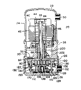
A scroll-type fluid apparatus generally shown in Figure
1 as a scroll compressor assembly is referred to by reference
numeral 20. As the preferred embodiment of the subject
invention is a hermetic scroll compressor assembly, the scroll
apparatus 20 is interchangeably referred to as a compressor
assembly 20. It will be readily apparent that the features of
the su~ject invention will lend themselves equally readily to
1 326005
- 16 -
use as a fluid expander, a fluid pump, or to scroll apparatus
which are not oE the hermetic type.
In the preferred embodiment, the compressor assembly
20 includes a hermetic shell 22 having an upper portion 24, a
lower portion 26 and an intermediate, central frame portion 28.
The central frame portion 28 is defined by a generally
cylindrical exterior shell 30 having a central frame portion 32
disposed across one end thereof.
Integral with the central frame portion 32 is a
generally cylindrical upper bearing housing 34, which is
substantially co-axial with the axis of the exterior shell
portion 30. A drive shaft aperture 36 extends axially through
the centre of the upper bearing housing 34, and an upper main
bearing 38 is disposed radially within the drive shaft receiving
aperture 36. Preferably, the upper main bearing 38 is a
rotation bearing made, for example, of sintered bronze or
similar material. The upper main bearing 38 may also be of the
roller or ball-type bearing. The upper main bearing 38 does not
preferably provide thrust load bearing capability.
A motor 40 is disposed within the upper portion 24 and
central shell portion 28 of the hermetic shell 22. The motor 40
is preferably a single-phase or three-phase electric motor
comprised of a stator 42 which is circumferentially disposed
about a rotor 44, with an annular space therebetween permitting
free rotation of the rotor 44 within the stator 42. A plurality
of long bolts or cap screws 46 are provided through appropriate
apertures in the stator plates into threaded apertures in the
~'
- 17 - ' 1 32 6 0 05
intermediate shell portion 28 for securing the motor within the
hermetic shell 22. For clarity, only one of thè long bolts 46
is shown.
It will be readily apparent to those skilled in the
art that alternative types of motors 40 and means of mounting
the motor 40 would be equally suitable for application in the
subject invention.
A discharge aperture 50 is shown in the upper shell
portion 24 for discharging high pressure fluid from the scroll
apparatus, and a shell suction aperture 52 is shown disposed in
the lower end of the lower shell portion 26 for receiving low
pressure fluid into the scroll apparatus. This permits
connection of the scroll apparatus 20 to a suitable fluid
system.
Preferably, the scroll compressor assembly 20 would be
connected to a refrigeration or air conditioning system. The
refrigeration system, shown generally in schematic
representation in Figure 17, includes a discharge line 54
connected between the shell discharge aperture 50 and a
condenser 60 for expelling heat from the refrigeration system
and condensing the refrigerant. A line 62 connects the
condenser to an expansion valve 64. The expansion valve may be
thermally actuated or electrically actuated in response to a
suitable controller tnot shown). Another line 66 connects the
expansion valve 64 to an evaporator 68 for transferring expanded
refrigerant from the expansion valve to the evaporator for
acceptance of heat. Finally, a refrigeration system suction
,.....
1 326005
- 18 -
line 70 transfers the evaporated refrigerant from the evaporator
68 to the compressor assembly 20, wherein the refrigerant is
compressed and returned to the refrigeration system.
It is believed that the general principles of
refrigeration systems capable of using such a compressor system
20 are well understood in the art, and that detailed explanation
of the devices and mechanisms suitable for constructing such a
refrigeration system need not be discussed in detail herein. It
is believed that it will also be apparent to those skilled in
the art that such a refrigeration or air conditioning system may
include multiple units of the compressor assembly 20 in parallel
or series connections, as well as multiple condensers or
evaporators and other components, hence such embodiments of
refrigeration systems need not be discussed here in detail.
Having described the general construction of the
compressor assembly 20, the features of the present invention
are now described in more detail. Referring again to Figure l
and more particularly to Figure 2 and 3, a scroll arrangement
having a first and a second scroll member is disclosed,
comprised of two upstanding, interfitting involute scroll wraps.
The first scroll member includes an upstanding first involute
scroll wrap 80 which is integral with a generally planar drive
scroll end plate 82. The drive scroll end plate 82 includes a
central drive shaft 84 extending oppositely the upstanding
involute scroll wrap 80. A discharge gallery 86 is defined by a
bore èxtending centrally through the axis of the drive shaft 84.
The discharge gallery 86 is in flow communication with
1 32600~
- 13 - -
a discharge aperture 88 defined by a generally central bore
through the drive scroll end plate 82~ The drive shaft 84
includes a first, relatively larger diameter portion 90
extending axially through the upper main bearing 38 for a free
rotational fit therein, and a second relatively smaller diameter
portion 92 which extends axially through the rotor 44 and is
affixed thereto. The rotor 44 may be affixed to the rotor
portion 92 of the drive shaft 84 by such means as a press fit or
a power transmitting key in juxtaposed keyways.
The second or idler scroll member includes a second,
idler scroll wrap 100 is disposed in interfitting contact with
the driven scroll wrap 80. The idler scroll wrap 100 is an
upstanding involute extending from an idler end plate 102. Two
rectilinear idler drive key stubs 103 extend upwardly on the
idler end plate 102. The idler key stubs 103 are disposed at
radially opposed positions outside the idler scroll wrap 100.
An idler shaft stub 104 extends from the idler end plate 102
oppositely the idler scroll wrap 100. The idler end plate 102
further includes a generally central pressure transmission bore
106 in flow communication with a pressure balance chamber 108
defined by a bore in the idler shaft stub 104.
An annular bearing 110, which may be a sleeve bearing
made of a sintered bronze material or may be of the roller or
ball type, is disposed within an annular wall defining an idler
bearing housing 112 which is integral with the lower hermetic
shell portion 26 for rotationally supporting the idler scroll
end plate 102 and idler scroll wrap 100.
. ~;.
1 326005
- 20 -
The drive scroll end plate 82 also includes two
extension members 120 extending from the drive scroll end plate
82 parallel the drive scroll wrap 80. The extension members 120
are disposed at radially opposed positions near the outer edge
of the drive scroll end plate 82, and are each comprised of
three portions or secti.ons: a first, spacing portion 122
concludes in a generally planar shoulder 124 spaced a certain
distance from and co-planar with the drive scroll end plate 82;
a second, rectilinear key portion 126; and a third, retainer
portion 128.
A ring 130 is disposed between and in sliding contact
with the shoulders 124 of the extension members 120 and the
idler end plate 102. The ring 130 thus serves as a spacer and
prevents undesirable oscillation or nutation of the idler end
plate 102 with respect to the drive scroll end plate 82. The
ring 130 is annular in form, extending non-contactingly about
the radial exterior of the scroll wraps 80 and 100 and further
having four rectilinear drive key slots 132a to 132d defined
through the ring 130 at equidistant intervals of approximately
gO about the annular body of the ring to comprise two pairs of
oppositely disposed slots 132, with slots 132a and 132c being
one pair and slots 132h and 132d being the second pair. As
shown particularly in Figure 3, the ring 130 includes four
generally rectilinear broadened portions through which the slots
132 are defined so that the slots 132 may be of the desired size
with the body of the ring 130 being minimized. It is, of
course, equally possible to form the ring with a radial
~}
.
- 2~ _ 132600~
thickness exceeding that required for the slots 132. However,
the form depicted in Figure 3 minimizes the mass of the ring 130
and aids in obtaining the desirable result of reducing the mass
of the rotating portion of the scroll apparatus, as the ring 130
is preferably made of steel or a similar material.
In the scroll apparatus, the second key portion 126 of
the extension members 120 extend through the drive slots 132a
and 132c in sliding engagement with the ring 130, while the
third portion 128 of the extension members 120 extend beyond the
ring 130. The idler key stubs 103 extend upward from the idler
end plate into the drive key slots 132b and 132d into sliding
engagement therewith. During operation of the scroll apparatus,
the ring 130 therefore acts as an Oldham Coupling means for
transferring rotation and torque from the extension members 120
through the ring 130 to the idler key stubs 103 and thereby
cause simultaneous rotation of the respective scroll members 80
and 100.
The idler end plate 102 further includes about its
exterior two clearance slots 140 which are concomitant with the
drive key slots 132a and 132c. The clearance slots 140 are
disposed at the radially outward end 142 of the idler end plate
102 so that the third, retainer portion 128 of the extension
members 120 extends through the clearance slots 140 parallel to,
but radially outward of, the lower bearing housing 112. The
clearance slots 140 are sized to provide sufficient clearance to
prevent interference between the third, retainer portion 126 and
the idler end plate 102 during the operation of the scroll
~'.
- 22 _ 1 3 2 6 0 0 5
apparatus.
An annular plate, the first scroll member compression
plate 150, is affixed to the cylindrical portions 128 of the
extension members 120. The compression plate 150 has an
annular, generally planar circumferential portion 152 about the
radially outward end thereof. This radially outward portion
includes one hole for each extension member 120, wherein the
third, retainer cylindrical portion 128 is fixed. The retainer
portion 128 may be affixed in the hole by such means as welding,
a press fit or a rotation-interlock fit between the components.
A depressed planar central portion 156 is parallel and
downwardly spaced a distance from the outer end portion 152 of
the compression plate 150. This central portion 156 preferably
includes a second, slightly more downwardly spaced area
describing a retaining shoulder 158 and a biasing surface 160.
A central aperture 162 is described by a bore through the axial
centre of the depressed portion 156. This central aperture 162
is of sufficient diameter to freely rotate about the lower
bearing housing 112.
A compression spring 170 is disposed between the
compression plate 150 and the idler end plate 102. The
compression spring 170 serves as a biasing element to force the
respective scroll end plates 82 and 102 toward each other. The
compression spring 170 exerts a force on the idler end plate 102
opposite from the idler scroll wrap 100 urging the tip 180 of
the idler scroll wrap into contact with the drive scroll end
plate 82, and transmits a like, opposing force through the
1~ '
.. j
1 326005
- 23 -
compression plate 150, extension members 120 and driven end
plate 82 to urge the riven scroll wrap tips 182 into contact
with the idle scroll end plate 102. In the preferred
embodiment, an annular channel 114 is concentrically disposed
about the idler end plate 102 for receiving an end of the spring
170.
The scroll assembly thus comprised of the respective
scroll end plates 82 and 102, together with the extension
members 120, the compression plate 150 and the compression
spring 170 provides the compressor assembly 20 with an axially
compliant scroll assembly. In the event of excessive pressure
or fluid slugging between the scroll wraps 80 and 100, the axial
biasing force generated by the compression spring 170 is
overcome and the pressure is relieved or fluid permitted to pass
by leakage flow between the respective scroll tips 180 and 182
and the opposing end plates 82 and 102.
Referring now to Figures 4, 4A, 5 and 6, it may be
seen that the drive shaft 84 rotates the drive scroll end plate
82 about a first axis A and that the idler shaft 104 rotates the
idler end plate 102 about a second axis B. The first axis A is
parallel to but not concentric with the second axis B. Since
the axes A and B are non-concentric, the respective scroll wraps
80 and 100 carried on the respective end plates 82 and 102 move
in a relative orbital motion when rotated synchronously.
A cylindrical lip 190 is generated at the lower end of
the central shell portion 28 about a first axis of generation
Cl. The lower shell portion 26 includes a cylindrical lower
B
- 24 _ 1 32 6 o 05
shell shoulder 192 defined in the upper edge. This lower shell
shoulder 192 is generated about a second axis of generation C2
The axis A of the drive shaft 84 is offset from the axis of
generation Cl in the central shell portion 28/ preferably by a
relatively small amount, such as 0.015 to 0.020 inches. The
axis B of the idler shaft 104 is also offset from the axis of
generation C2 in the lower shell portion 26, but preferably by a
larger amount of offset than the offset between the axes A and
Cl, for example, in an amount approximately equal to the orbit
radius defined by the scroll wraps 80 and 100, as particularly
shown in Figure 4. Figure 4A shows the alternative embodiment
wherein the axis B of the idler shaft 104 is offset from the
axis of generation C2 by a smaller amount than the offset of the
axis A from Cl.
During assembly of the hermetic shell 22, the central
shell lip 190 engages the lower shell shoulder 192. The lower
shell shoulder 192 fits closely about the exterior of the
central shell lip 190. Preferably, the lower shell shoulder 192
and the central shell lip 190 are sized to permit a close fit
therebetween suitable for welding. The axis of generation Cl of
the central shell portion 28 and the axis of generation C2 of
the lower shell portion are concentric after assembly of the
hermetic shell 22, comprising a single axis C (i.e., C = Cl =
C2), which is offset from both the axis A and B. The lower
shell portion 26 and the central shell portion 28 are relatively
positionable during the assembly of the hermetic shell 22 to
adjust the flank clearance between the respective scroll wraps
B
,
- 25 ~ 1 3~600-'
80 and 100. Indicator markings such as U for the central shell
portion 28 and L for the lower shell portion 26 may be provided
to visually indicate, for ease of assembly, the relative
position of the respective shell portions about the common axis
C.
Figures 5 and 6 more clearly show the results of
positioning of the central shell portion 28 with respect to the
lower shell portion 26. The maximum orbit radius between the
respective scrol.l wraps 80 and 100 is equal to the distance that
A is removed from C plus the distance that B is removed from C
and the minimum orbit radius is equal to the distance that B is
removed from C less the difference that A is removed from C.
Orbit radius as used herein should be understood to refer to the
offset of or relative orbit distance defined between the scroll
wrap elements 80 and 100. As the scroll wrap flank surfaces 184
of the idler scroll wrap contact the flank surfaces 186 of the
driven scroll wrap 80, it is necessary to provide an appropriate
clearance between the respective flanks 184 and 186 to prevent
excessive leakage and loss of efficiency or conversely excessive
wear to the flank surfaces due to lack of appropriate flank
clearance. The appropriate flank clearance is obtained by
adjusting the orbit radius according to the foregoing formula
during assembly of the compressor assembly 20, positioning the
central shell lip 190 with respect to the lower shell shoulder
lg2 prior to welding or otherwise finally assembling the
hermetic shell 22.
In operation, the motor 40 of the compressor assembly
- 26 _ 1 32hO05
20 is connected to an appropriate electrical supply and actuated
to cause rotation of the rotor 44. The rotor 44 in turn rotates
the drive shaft 84, driving the driven end plate 82. The
extension members 120, slidingly engaged in the drive key slots
132 of the ring 130, cause concurrent rotation of the idler
scroll end plate 102 with the drive scroll end plate 82. The
drive shaft 84 rotates about the axis A and the idler scroll end
plate 102 rotates about the axis B on the idler shaft stub 104.
Because the axis A and B are non~concentric, a relative orbital
motion is set up between the driven scroll wrap 80 and the idler
scroll wrap 100, causing a plurality of chambers to be formed
between the idler scroll flanks 184 and the driven scroll flanks
186, which are in moving line contact. These chambers are of
decreasing volume toward the radially inward ends of the
respective scroll wraps 80 and 100, such that fluid is drawn
into the chambers as they form at the radially outward ends of
the respective scroll wraps 80 and 100 and compressed as it is
moved toward the radially inward ends of the respective scroll
wraps 80 and 100.
The compressed fluid is then discharged from the
scroll wraps through discharge aperture 88 and thence through
the discharge gallery 86 into the discharge pressure portion of
the hermetic shell defined in the upper shell portion 24.
Simultaneously, a portion of the compressed, discharge pressure
fluid enters the pressure balance chamber 108 through the
pressure transmission bore 106. The discharge pressure fluid in
the pressure balance chamber lQ8 acts to force the idler scroll
- 27 _ 1 32 6 0 0 ~
shaft stub 104 axially from the lower bearing housing 112. This
force is in opposition to a simultaneous force of discharge
pressure fluid acting upon the drive shaft 84 to axially Eorce
the drive shaft 84 toward the idler end plate 102.
Lubrication of the bearings 38 and 110, as well as the
other components of the compressor assembly 20, is accomplished
by a depression in the central frame portion 32 which acts as a
reservoir 200 for lubricant ~ithin the hermetic shell 22.
Lubricant is transferred from the reservoir 200 to the upper
main bearing 38 through a lubricant passage 202 in the central
frame passage extending between the reservoir 200 and the upper
main bearing 38. Lubricant is preferably forced through the
passage 202 by the action on its surface of discharge pressure
fluid, the lubricant passing through the lubricant passage 202
to the main bearing 38 and hence to the suction pressure portion
defined by the lower shell portion 26. The lubricant
accumulating in the suction pressure portion of the compressor
assembly 20 is entrained into the suction pressure fluid and
drawn through the scroll assembly, lubricating the moving parts
and being compressed and discharged with the fluid. The
lubricant is then disentrained in the discharge pressure portion
of the hermetic shell 22 defined by the upper shell portion 24
and the central shell portion 28, flowing downwardly through the
annular space between the rotor 44 and stator 42 and about the
exterior of the stator 42 to return to the lubricant reservoir
200.
The amount of force exerted upon the idler scroll end
: ~ .
- 28 ~ 1 32 6 0 0 5
plate 102 by the drive shaft 84 and the amount of force exerted
upon the drive scroll end plate 82 by the action of discharge
pressure upon the idler scroll shaft stub 104 is determined by
the plan view areas of the respective shafts and therefore by
the relative si~ing of the diameters of these shafts. The drive
shaft 84 has a plan view area diameter D and the idler shaft
stub 104 has a plan view area diameter I. As the compressor
assembly 20 is preferably oriented with a vertical axis having
the motor 40 disposed above the scrolls 80 and 100, the
diameters D and I can be calculated according to the capacities
and component weights of the particular machine. For example, D
and I may be made equal, so that the weight of the scrolls 80
and 100, the drive shaft 84 and the rotor 44 is transmitted to
the lower main bearing 110.
Alternatively, the diameter I may be made larger than
the diameter D so that the weight of the scrolls 80 and 100, the
drive shaft 84 and the rotor 44 will be supported by the action
of discharge pressure fluid upon the idler shaft stub 104,
obviating the need for a thrust bearing in the lower bearing
housing 112. Also, it would be possible to expose the plan view
area of diameter I to an intermediate pressure fluid for a
lesser pressure balancing effect. Finally, the value of I may
be made larger than the diameter D to the extent that the force
exerted by the idler shaft stub 104 exceeds that exerted by the
action of discharge pressure fluid upon the drive shaft 84 and
the combined weight of the scrolls 80 and 100, the drive shaft
84 and the rotor 44, in which case some provision for accepting
~,~
: ~ .
1 326005
- 29 -
a thrust load wlll be necessary in the driven scroll 80 or in
the upper main bearing 38. Examples of these alternatives will
appear in alternative embodiments of the subject invention,
however, in the preferred embodiment the diameter I is slightly
larger than the diameter D so as to balance the weight of the
scrolls 80 and 100, the drive shaft 84 and the rotor 44 when in
operation.
It should be noted that when the same part or feature
is shown in more than one of the figures, it will be labelled
with the corresponding reference numeral to aid in the
understanding of the subject invention. Furthermore, reference
should be had to all of the figures necessary to aid in the
understanding of the specification even where a particular
figure is referred to, as all reference numerals are not
displayed in all figures in order to minimize confusion. When
the same part or feature appears in a figure representing or
disclosing an alternative embodiment of that part or feature, it
is again labelled with the same reference numeral, followed ~y a
numeric suffix to correspond with the designation of that
alternative embodiment in the specification. The numeric
designation of the alternate embodiment does not correspond to
its preference but rather is intended to aid in the
understanding of the subject invention.
It should also be noted that the scroll apparatus can
function as an expansion engine or as a fluid compression
apparatus by directing fluid into the discharge pressure port to
be expanded from the radially inward ends to the radially
~ 30 ~ 1 32 6 0 0 5
outward ends of the respective scroll wraps 80 and 100. This
can be accomplished simply by establishing th~ appropriate
direction of rotation with respect to the orientation of the
scroll wrap involutes.
Turning now to Figures 7, 7A and 7B, a first
alternative embodiment of the subject invention is disclosed.
This first alternative embodiment includes a lower face 210~1 in
the central frame portion 32-1 having an annular groove 220-1
defined concentrically about and radially removed from the drive
shaft 84-1. This annular groove 220-1 is defined by a circular
interior side wall 222-1, a concentric exterior side wall 224-1
of relatively larger diameter and a recessed planar surface 226-
1 in the base of the groove 220-1 adjoining the interior side
wall 222-1 and the exterior side wall 224-1.
An annular bearing 230-1 of rectangular cross-section
is disposed within the annular groove 220-1. The annular
bearing 230-1, as shown more particularly in Figure 7A, includes
a first planar surface 232-1 for engaging the driven scroll end
plate 82-1 and a second, exterior surface 234-1 for engagement
with the exterior side wall 224-1. A third engagement face 236-
1 is at the upper end of the second surface 234-1 and is
parallel to the first surface 232-1, whereas the second surface
224-1 is normal to and extends between the first surface 232-1
and the third surface 236-1.
An annular thrust spring 240-1, as shown in Figures 7
7B, is disposed between the third surface 236-1 of the annular
bearing 230-1 and the recessed surface 226-1 of the annular
~'
i ~
- 31 - 1 3 2 6 0 0 )
groove 220-1. The annular spring 240-1 is comprised of three
portions; a Eirst, relatively planar radially exterior portion
242-1, a second, radially interior planar portion 244-1 and an
angular portion 246-1 adjoining the exterior planar portion 242-
1 and the interior portion 244-1. The exterior planar portion
242-1 and the interior planar portion 244-1 are parallel and
spaced apart a distance determined by an angle theta of the
angular portion 246-1. Preferably, the annular spring 240 is a
solid annulus having no holes or discontinuities. The annular
spring 240-1 may, for example, be formed of spring steel by such
means as die-press operations.
Preferably, the second surface 234-1 of the annular
bearing 230-1 is sized to a diameter slightly larger than the
exterior side wall 224-1 of the annular groove 220-1 to cause a
slight compression in contact therebetween. The annular spring
240-1 is disposed between the annular bearing 230-1 and the
annular groove 220-1, with the interior planar portion 244-1 in
contact with the recessed surface 226-1 and the exterior planar
portion 242-1 in biasing contact with the third face 236-1 of
the annular bearing 230-1. In order to achieve the appropriate
biasing effect of the thrust spring 240-1 in the assembled
compressor assembly 20-1, the lower base 210-1 should be within
.020 and .040 inches of the driven scroll end plate 82-1 when
the compressor assembly 20-1 is operating, although this will
vary according to the compressor component sizing.
When the compressor assembly 20-1 is assembled, the
idler scroll shaft stub is placed in the lower main bearing 110-
:
,, .
. ~
- 32 -i 1 3 2 6 0 0 ~
1, and the central shell lip 192-1 is placed into engagement
with the lower shell shoulder 190-1, causing the annular bearing
230-1 to contact the driven scroll end plate 82-1. This contact
causes the annular spring 240-1 to become biased so that the
angle theta of the angular portion 246-1 is moved to the angle
thetal, as seen in Figure 7B. In this first alternative
embodiment, the diameter I-l is larger than the diameter D-l so
that the force of discharge fluid acting upon the idler scroll
shaft stub 104-1 biases the scroll assembly 80-1 and 100-1
toward the annular bearing 230-1. This annular bearing assembly
230-1 and 240-1 would be useful in a compressor assembly 20-1
experiencing substantial variations in load conditions which
might cause axial oscillation of the scroll assembly 80-1 and
100-1 .
Also, in the first alternative embodiment, the
exterior of the cylindrical portion 128-1 of the extension
member 120-1 is threaded to accept retaining nuts 250-1. The
threaded cylindrical portions 128-1 extend through corresponding
holes in a planar compression plate 150-1. The compression
plate 15~-1 has a relatively slightly depressed planar biasing
surface 160-1 with an annular retaining shoulder 158-1 extending
radially about the biasing surface 160-1. An annular belleville
type spring 260-1 extends angularly from the biasing sur~ace
160-1 for engaging a slider thrust ring 270-1. The annular
slider thrust ring 270-1 is of an L-shaped cross-section
comprising a retaining ring shoulder 272-1 on the downward face
of the slider thrust ring 270 and a planar idler end plate
1 326005
- 33 -
engaging surface 274-1 on the upper face of the slider thrust
ring 270-1.
The axial compressive force is therefore applied
through the belleville spring 260-1 and slider thrust ring 270-1
from the extension members 120-1 to the idler scroll end plate
102-1, in a fashion similar to that of the preferred embodiment.
However, unlike the compression spring 170-1, the relative
orbital motion o~ the scroll apparatus 80-1 and 100-1 is
absorbed by sliding contact between the slider thrust ring 270-1
and the idler end plate 102-1.
The use of the retaining nuts 250-1 provides
considerable adjustment of the compressive force supplied by the
belleville spring 260-1. The belleville spring 260-1 provides
more limited axial compliance than the preferred embodiment and
would therefore be of more limited application.
Finally, a bore defining a lubricant metering passage
280-1 extends through the central frame portion 32-1 to inter-
connect the reservoir 200-1 to the lower face 210-1. In
operation, the lubricant metering passage 280-1 permits a
metered flow of lubricant to be forced by discharge pressure
from the lubricant reservoir 200 to the suction pressure portion
of the hermetic shell 22-1 in the lower hermetic shell portion
26-1. This lubricant is also entrained with the flow of
lubricant at suction pressure, lubricating the scroll apparatus
components as it is entrained with the fiuid. The lubricant
thus supplied follows a cycle then similar to the lubricant
supplied through the upper main bearing 38-1. In operation,
` ~ 'r
1 326005
- 34 -
this first alternative embodiment is not substantially different
from that described for the preferred embodiment, although it
may be subject to different operating parameters as discussed
above.
A second alternative embodiment is disclosed in Figure
8. The driven scroll end plate 82-2 is provided with a series
of radially projecting nubs 300-2 about its circumference.
Identical, corresponding nubs 302-2 are provided on the idler
scroll end plate 102-2. As seen in Figure 9, eight of these
nubs 300-2 are provided, however, any number of nubs 300-2 on
the order of two or more are suitable. It is preferable to use
at least two of the nubs 300-2, with corresponding nubs 302-2,
at radially opposed positions about the scroll end plates 82-2
and 102-2 so that the scroll apparatus will be dynamically
balanced during operation, and so that oscillation or nutation
of the scroll member end plates 82 and 102 relative to each
other will be minimized.
Tension springs 310-2 extend between and directly
connect each nub 300-2 on the driven scroll end plate 82-2 to
the corresponding nub 302-2 on the idler scroll end plate 102-2.
The tension springs 310-2 bias the respective scroll wrap end
plates 82-2 and 102-2 into axial compliance. This alternative
embodiment is exemplified in Figure 8A, wherein the extension
members 120-2 and the drive ring 130-2 comprise the coupling for
causing simultaneous rotation of the idler scroll member 102-2
with the drive scroll member 82-2, while the tension springs
310~2 provide the means for biasing the second scroll member
1 326005
102-2 to provide axial compliance between the second scroll
member 102-2 and the first scroll member 82-2. These tension
springs 310-2 may alternatively act as substitutes for the
extension members 120 and 120-1 by causing simultaneous rotary
motion of the idler scroll end plate 102-2 with the driven
scroll end plate 82-2, in ]ieu of an Oldham Coupling as in the
previous embodiments. The extension members 120 and the drive
ring 130 which comprise the Oldham Coupling are not shown in
Figure 8, but it is understood that this is done only to clarify
the nature of the tension springs 310-2, and that the Oldham
Coupling members would be especially applicable to this
embodiment if desired, as shown in Figure 8A. The tension
springs 310 thus may in certain embodiments permit axial
compliance of the respective scroll end plates and radial
changes or separation in the scroll wrap blank clearance when
excessive pressure is developed between the scroll wraps 80-2
and 100-2 or when incompressible fluids enter the scroll wraps.
This is simply accomplished, as the tensile force exerted by the
tension springs 310 is overcome by these excessive pressures and
the springs 310-2 extend to permit both radial changes and axial
compliance when an Oldham Coupling or the like is not used. It
would also be possible, of course, to use the tension springs
310-2 solely to provide axial compliance while using extension
members and a ring as described above.
The second alternative embodiment also discloses an
alternative thrust bearing for preventing excessive axial
oscillation of the scroll apparatus. The lower main bearing
, B
- 36'- 1 32 60 0 5
housing 112-2 is provided with an upper shoulder 115-2 having an
annular thrust bearing 320-2 disposed about the idler scroll
shafts stub 104-2. This lower annular thrust bearing 320-2 may
be formed of a sintered bronze material, or it may be a roller
or ball type bearing and may be spring or elastomerically
mounted. The construction of such a thrust bearing 320-2 is not
disclosed in detail, as the construction of thrust bearings in
general is believed to be generally understood by those skilled
in the art.
The scroll apparatus is biased into contact with the
lower thrust bearing 320-2 by providing alternately an idler
shaft stub diameter I-2 smaller than the drive shaft diameter D-
2 or, as shown in Figure 8, a pressure transmission bore 106-2
which is in flow communication with an intermediate chamber of
the scroll wraps 80-2 and 100-2 for providing fluid compressed
to less than discharge pressure to the pressure balance chamber
108-2. The force acting upon the idler shaft stub 104-2 is thus
relatively lower than the force acting upon the drive shaft 84-2
so that at least a portion of the force exerted by the weight of
the scroll apparatus 80-2 and 100-2, the drive shaft 84-2 and
the weight of the rotor 44-2 will be born by the thrust bearing
320-2.
Yet another feature of the second alternative
embodiment is a lower bearing oil supply system 330-2. This oil
supply system 330-2 is comprised of a bore 332-2 in the lower
face 210-2 of the central frame portion 32-2, a bore 334-2 in
the lower bearing housing 112-2, and a lubricant feed tube 336-2
; ~
~ 37 - 1 32600~
connecting between the bore 332-2 and the bore 334-2. In
operation, lubricant is forced by discharge pressure fluid
through the bore 332-2 from the lubricant reservoir 200-2 into
the lubricant feed tube 336-2 and hence to the bore in the lower
bearing housing 334-2, whereupon it lubricates the lower main
bearing 110-2. The lubricant feed tube is secured in the
respective bores by retaining sleeves 338-2. It will be
appreciated that while the flow of lubricant is enhanced where
intermediate pressure fluid is used in the pressure balance
chamber 108-2, the lower bearing oil supply system 330-2 would
nonetheless function where discharge pressure fluid is utilized
in the pressure balanced chamber 108-2, due to the slight
leakage of discharge pressure fluid through the lower main
bearing 110-2 to the suction pressure portion of the hermetic
shell 26-2.
It will be apparent that with slight modification this
oil supply system 330-2 is applicable generally to the
compressor assembly 20 in any of its embodiments where a need
for additional lubricant is necessary to the lower main bearing
110-2.
Figure 8B shows another combination of features of the
scroll apparatus in which the scroll end plate 102-2 has no
pressure transmission bore 106-2, as shown in Figure 8, and in
which the oil supply system is provided with a venturi portion
339-2 for supplying oil at an intermediate pressure to the lower
bearing housing 334-2. Since the intermediate pressure includes
any pressure between the discharge pressure and the suction
- 38 _ 1 32 6 0 0~
pressure, it will be appreciated that the pressure acting upon
the plan view area defined by the diameter I will bias the
second scroll end plate according to the pressure supplied.
Those skilled in the art will recognize that, as will
be discussed in more detail subsequently, the need for the
thrust bearing 320-2 may be obviated by providing discharge
pressure fluid, as shown in Figures 1, 2, or discharge pressure
lubricant as shown in Figure 8C. Where the thrust bearing 320-2
is provided in combination with fluid at intermediate pressure
acting upon the diameter I of the idler shaft stub 104-2, the
weight or load carried by the thrust bearing 320-2 will increase
as the intermediate pressure provided, either by fluid or
lubricant, tends toward suction pressure with the result that
the thrust bearing 320-2 supports the weight of the scrolls 80
and 100, the drive shaft 84 and the rotor 44, as shown in Figure
8B. In Figure 8B, the provided intermediate pressure is
determined by the venturi portion 339-2.
It will also be appreciated that the alternative
embodiment of the scroll apparatus in Figure 8C exemplifies the
alternative where the tension springs 310-2 only substitute for
the extension members 120 to cause simultaneous rotary motion of
the scroll end plates 102 and 82, and the alternative of
providing a diameter I of the scroll shaft 104 subject to
discharge pressure so that the need for a thrust bearing 320 in
the lower bearing housing 112 is obviated.
Figures 9 and 10 disclose alternate means of
connecting the tension springs 310-2 to the nubs 300-2 and 302-
~'
- 39 -' 1 3 2 6 0 05
2. Figure 9 shows nubs 300-2 and 302-2 provided with suitable
holes 304-2 for acceptin~ the hook-like ends of the tension
springs 310-2, whereas Figure 10 shows nubs 300-2 and 302-2
equipped with grooves 306-2 extending circumferentially across
the nubs 300-2 and 302-2 for retaining the hook-like ends of the
tension spring 310-2.
As in the foregoing embodiments, radial compliance is
initially achieved during assembly by properly rotating the
central frame portion 30-2 with respect to the lower shell
portion 26-2. The adjustment of flank clearance in this second
embodiment of the subject invention also serves to adjust the
tension provided in tension springs 310-2 to the desired level.
A third alternative embodiment is disclosed in Figures
11 through 14, generally. As with the preferred and first
alternative embodiments, extension members 120-3 extend through
slots 132-3 in spacing ring 130-3 and through drive slots 140-3
in an idler scroll end plate 102-3. However, the third portion
128-3 is forked, providing a slot for accepting a centrifugal
pivot element 342-3. The forked portion 128-3 of the extension
member 120-3 and the centrifugal pivot 342-3 are provided with
corresponding apertures 344-3 for accepting a pivot pin 346-3 to
pivotally link the centrifugal pivot 342-3 and the extension
member 120-3. The centrifugal pivot 342-3 has a centre of mass
CPm which is above the aperture 344-3, such that during rotation
of the scroll apparatus, the centre of mass CPm causes the
centrifugal pivot 342-3 to pivot simultaneously upwardly and
outwardly~ The centrifugal pivot element 342-3 is comprised of
~ 40 ~ 1 32 6 0 0 5
a pivot arm 348-3 which is interfit into the slotted portion
128-3 and which contains the aperture 344-3 for the pivot pin
346-3, and a rod portion 350-3 having an upwardly directed
conical recess 352-3 having a hemispheric lower end. The
upwardly directed recess 352-3 contains a linking rod 354-3
extending between the hemispheric bottom of the recess 352-3 and
corresponding hemispheric depressions 356-3 in the idler scroll
end plate 102-3. The linking rod 354-3 has ends rounded to
correspond to the conical recess 352-3 and the idler end plate
depressions 356-3, whereby the relative orbital movement of the
scroll end plates 82-3 and 102-3 is readily absorbed during the
rotation of the scroll apparatus. A top view of the centrifugal
pivot 342-3 and linking rod 354-3 is shown in Figure 13.
As in the second alternative embodiment, a thrust
bearing 320-3 is provided for absorbing a portion of the axial
force of the scroll apparatus resulting from the weight of the
drive shaft 84-3, the rotor 44-3 and the pressure acting upon
the drive shaft diameter D-3.
Figure 14 shows the position of the centrifugal pivot
342-3 when the scroll apparatus is in the non-operating
condition. In this position, the mass of the centrifugal pivot
342-3 acting through the centre of mass CPm causes the
centrifugal pivot 342-3 to drop away from the idler scroll end
plate 102-3. Figures 11 and 12 show the compressor assembly 20-3
with the centrifugal pivots 342-3 in the upper, operating
position.
This third embodiment of the subject invention has the
~`
- 41 ~ 1 32 6 0 0 5
advantage of providing a compressor assembly 20-3 with an
unloaded axial compliance condition when not operating. As the
motor 40-3 comes up to speed after actuation the centrifugal
pivots 342-3 move to the operating position, causing an axial
compliance load on the scroll wrap tips 180-3 and 182-3 in
cooperation with the axial compliance force generated by the
discharge gas pressures acting upon the drive shaft 84-3 and
idler shaft stub 104-3. Thus, when the compressor assembly 20-3
is actuated, the load experienced by the motor 40-3 is initially
very small and moves to full load automatically by the action of
the centrifugal pivots 342-3 as the compressor is brought up to
speed. Additionally, the linking rods 354-3 have a very low
coefficient of friction in operation, as the rounded ends of the
linking rod 354-3 cooperate with the conical recesses 352-3 and
356-3 to absorb the relative orbital motion of the scroll
apparatus end plates 82-3 and 102-3. In other respects, the
operation of the third alternative embodiment is similar to the
operation of the preferred embodiment hereinbefore described.
Figures 15 and 16 disclose a fourth alternative
embodiment which is substantially similar to that of the third
alternative embodiment. In this fourth alternative embodiment,
the end portion 128-4 of the extension members 120-4 are
truncated and the apertures 344-4 for the pivot pin 346-4 are
moved relatively upward of the centre of mass CPm of the
centrifugal pivot element 342-4. The centrifugal pivot 342-4 is
arranged with the centre of mass CPm located radially outward of
and below the aperture 344-4, so that when the compressor
~fi !
- 42 -' 1 32 6 0 0 ~
assembly 20-4 is in operation, a rounded thrust surface 358-4
will slidingly engage the idler end plate 102-4. In this fourth
embodiment, the idler scroll end plate 102-4 has an extended
outer radial portion for contact with the thrust surface 358-4.
Preferably, the thrust surface 358-4 will be a rounded
protuberance on the upper surface of the centrifugal pivot 342-
4.
An annular thrust shoulder 360-4 extends downward from
the lower face 210-4 of the central frame portion 32-4 for
accepting the upward thrust of the scroll apparatus. To achieve
this upward thrust, the diameter I-4 is greater than the
diameter D-4 in a ratio such that the pressure of discharge
fluid acting upon the diameter I-4 exceeds the combination of
the pressure of discharge fluid acting upon the diameter of the
drive shaft D-4 and the weight of the components of the scroll
apparatus in the compressor assembly 20-4. Lubrication of the
thrust shoulder 360-4 is accomplished during the operation of
the compressor assembly 20-4 by lubricant flowing through the
upper main bearing 38-4 and then between the thrust shoulder
360-4 and the driven end plate 82-4.
In operati.on, this fourth alternative embodiment is
substantially the same as the third alternative embodiment.
However, the operation of the compressor assembly 20-4 of the
fourth alternative embodiment may be slightly less efficient
than that of the compressor assembly 20-3 of the third
alternative embodiment due to friction between the thrust
surface 358-4 and the idler scroll end plate 102-4 as the idler
_ 43~ 1 32 6 0 0 5
scroll end plate 102-4 orbits with respect to the driven scroll
end plate 82-4. An advantage of the fourth alternative
embodiment lies in its simplicity of construction.
A fifth alternative embodiment is disclosed in Figure
18. In this embodiment, the extension members 120-5 and the
coupling ring 130-5 drive the second scroll member end plate
102-5 simultaneously with the first scroll member end plate 82-
5. As in the preferred embodiment, pressurized fluid enters the
lower bearing housing 112-5 directly from the scroll wraps 80-5
and 100-5 through the pressure transmission bore 106-5 so that
discharge pressure acts directly upon the plan view area of the
idler shaft stub 104-5 to bias the second scroll member end
plate 102-5 compliantly toward the first scroll member end plate
82-5,
A sixth alternative embodiment is disclosed in Figure
19. This embodiment is substantially similar to the embodiment
disclosed in Figure 18 with the distinction that the pressure
transmission bore 106-6 is arranged to provide communication
from an intermediate pressure portion of the scroll wraps 82-6
and 102-6 so that fluid acts at an intermediate pressure upon
the plan view area of the idler shaft stub 104-6, as shown also
in Figure 8~
Yalues of diameters I and D are not been given
specifically, as it is felt that those skilled in the art would
be readily capable of calculating such values for various
applications of a compressor assembly 20~ However, an exemplary
compressor assembly 20 might be in the 5 ton to 15 ton capacity
'.'' ~.
- 44 -i 1 3 2 6 0 0 ~
range for use in a refrigeration or air conditioning system as
hereinbefore described. In such a system, the refrigerant fluid
pressure experienced at the shell suction aperture 52 would
typically be in the range of 0 to 100 pounds per square inch,
while the fluid refrigerant discharge pressure provided by
compressor assembly 20 at the shell discharge port 50 would
typically be in the range of 200 to 400 pounds per square inch.
The combined weight of the rotor 44 and the drive shaft 84 would
be expected to be within the range of 5 to 35 pounds. The
diameter I then, for example, might be 125% of the diameter D
such that the net axial thrust load of the idler scroll stub 104
would support the scroll apparatus components 80 and 100, and
the rotor 44 during normal operation of the compressor assembly
20. This could eliminate the requirement for a thrust bearing
to absorb axial loads within the compressor assembly 20,
reducing the cost of construction and maintenance of such a
compressor assembly 20 while increasing the efficiency of its
operation.
Alternatively, it is possible in all embodiments
described to eliminate the pressure transmission bore 106 and
provide pressurization of the pressure balance chamber 108 with
the lubricating oil supplied through the lower bearing oil
supply system 330, as the lubricating oil is supplied at
discharge pressure from the reservoir 200. This would assure
constant pressure lubrication of the lower annular bearing 110
and a constant balance pressure on the plan view area of the
idler shaft stub 104 as defined by the diameter I. Furthermore,
1`326005
- 45 ~
it would be possible to provide lubricating oil at an
intermediate pressure throttled from the discharge pressure to
control the balance pressure exerted on the idler sha~t stub 104
by providing, for example, a throttling valve or a venturi, as
exemplified in Figure 8B, discussed above, in the lubricant feed
tube 336. It is believed that specific examples of controlling
the pressure or volume of the lubricating oil flow need not be
detailed herein, as the method and means of controlling the
pressure or volume of fluid flowing in a tube is believed to be
well known to those skilled in the art.
In Figure 20, a seventh alternative embodiment of the
scroll apparatus is presented. In this embodiment, the
extension members 120-7 and the coupling ring 130-7 drive the
second scroll member end plate 102-7 simultaneously with the
first scroll member end plate 82-7 as in Figures 18 and 19.
However, the biasing force for providing the axial compliance is
derived from the balance pressure exerted on the idler shaft
stub 104-7 and is determined by the plan view area of the idler
shaft stub 104-7 and the operating discharge pressure of the
scroll apparatus. This is accomplished with the oil supply
system 320-7, which supplies lubricating oil to the lower
bearing housing 112-7 at discharge pressure, as discussed above.
In Figure 21, an eighth alternative embodiment of the
scroll apparatus is presented. This alternative embodiment is
substantially similar to the alternative embodiment disclosed in
Figure 20, including the extension members 120-8 and the
coupling 130-8 in conjunction with the oil supply system 320-8,
~ B
1 32600~i
- 46 --
with the addition of the venturi portion 339-8. As above, the
oil in the lower bearing housing 112-8 is a pressurized fluid
acting upon the plan view area of the idler shaft stub 104-8 to
axially bias the second scroll member 102-8 compliantly toward
the first scroll member 82-8. This embodiment differs from the
preceding seventh embodiment in that the lubricating oil is
provided at an intermediate pressure throttled from the
discharge pressure so that the balance pressure is controlled.
Also, it may be desirable to provide shaft seals at
the upper main bearing 38 and the lower annular bearing 110 for
additionally sealing between the suction pressure and discharge
pressure portions of the scroll apparatus. In scroll apparatus
utilizing the aforementioned roller or ball type bearings as the
upper main bearing 38 and the lower annular bearing 110, such
shaft seals would be essential, as these types of bearings would
be ineffective to prevent flow of the fluid or refrigerant from
the discharge pressure portion 24 to the suction pressure
portion 26 of the hermetic shell 22.
The compressor assembly 20 is a substantial
advancement over the prior art of scroll apparatus. The
frictional losses due to axial thrust loads within the
compressor can be reduced to a minimum by the pressure balancing
through the diameters I and D of the drive shaft 84 and idler
shat stub 104, while at the same time the net efficiency of
compression is maintained by the biasing member acting upon the
respective end plates through the extension members or tension
springs as shown in the alternative embodiments. Furthermore,
;
~. ~
1 326005
- 47
the requirement of a radial compliance device is eliminated by
the provision of non-concentric scroll axes in the hermetic
shell to adjust the flank clearance between the scroll wraps
during assembly. This substantially reduces the requirement for
expensive and time consuming high accuracy machining processes.
The need for such multiple bearings for supporting drive shafts
and idler shafts, the misalignment of which typically causes
unnecessary wear in the scroll wraps of co-rotating scrolls, is
eliminated by the biasing means directly connecting the
respective scroll wrap end plates. The annular, spring loaded
thrust bearing also provides a means for preventing axial
oscillations of a co-rotating scroll apparatus while
simultaneously maintaining a minimum friction loss. Utilization
of the pressure of discharge fluid to provide lubricant from the
lubricant reservoir eliminates the need for a potentially
difficult to maintain and expensive pump component within the
hermetic shell, further reducing the potential requirements for
maintenance in the compressor assembly 20. It will be
appreciated, therefore, that the compressor assembly 20 is
substantially simpler, more reliable and more efficient than
previous scroll apparatus.
Modifications to the preferred and alternate
embodiments of the subject invention will be apparent to those
skilled in the art within the scope of the claims that follow
hereinbelow.
What is claimed is:
'~ ~