Note: Descriptions are shown in the official language in which they were submitted.
1 326068
C-I-L 730
--1--
BACKG~OUND OF INVENTION
1. Field of the Invention
The present invention relates to an initiating system
for providing firing energy to a detonator used in blasting
with explosives. More specifically, the invention relates to
such a system wherein light energy is converted to electrical
energy for the firing of a detonator.
2. Description of Prior Art
The mining and construction industries are very aware of
the hazards involved in the use of electric detonators for
blasting in conductive underground ore bodies where the
detonators are susceptible to accidental initiation by stray
currents created by high voltage electrical equipment. It is
15 also known that electric detonators are prone to initiation
by electrostatic discharges generated by explosive loading
equipment or by lighting strikes in conductive ore deposits
which produce high voltage transients at the working face.
In surface blasting applications at construction sites,
20 for example, hazards are likely to arise when blasting is
conducted with electric detonators in relatively close
proximity to radio or radar transmitting antennas. The
American National Standards Institute has established safe
distances of blasting operations from fixed radio frequency
25 transmitting antennas, but there is little control over
mobile transmitters which frequently transmit with power
levels well in excess of the legal limit of 5 watts.
Although mobile transmitters per se are banned from blasting
sites, there is little control over vehicles transmitting
30 from nearby public roads.
The hazards arising from static discharges, electrical
storms, ground currents, electric power generators,
transmission lines, rf antennas or electromagnetic fields
generated by other means are all additive. At some blasti~
35 locations, complex situations may arise which make it
1 32 6 0 6~ C-I-L 730
necessary to call in expert technical assistance to determine
whether a hazard exists. This results in additional expense
and delays for the mine operator or blasting contractor.
Over the past several years, many mines and quarries
have converted to the use of non-electric blasting systems in
order to avoid the hazards of electric initiated detonators
previously described. Typically, a non-electric blasting
system employs a shock wave conductor as the initiator means
for a detonator. A shock wave conductor or shock tube
comprises a hollow, non-conductive plastic tube with a thin
layer of explosive dust deposited on its inner surface. When
initiated at one end by detonating cord or similar shock
producing device, a shock front propagates along and within
the length of the tube to initiate a detonator attached at
the opposite end.
In a typical shock tube blast, the boreholes to be
loaded with explosives are each primed with a delay detonator
having a specified delay time and to which a length of shock
tube is attached. The ends of the tubing extending from each
borehole are connected to a common detonating cord trunkline
by means of connectors. A blasting round hooked up in this
manner is completely non-electric and non-conductive and is
therefore safe from any inadvertent electrical initiation.
To initiate a blast which uses shock tube and
non-electric detonators and a detonating cord trunkline, it
has been common practice to set off the detonating cord by
means of an attached electric detonator. As a safe practice,
some larger mines are evacuated, and the blasting of multiple
faces located throughout the mine is controlled electrically
by a central blasting station on surface. The introduction
of an electric detonator to initiate the trunkline however,
defeats the safety advantages gained through the use of the
shock tube system. For this reason, many mining managers
have elected not to use fully electric central blasting
systems and have been searching for alternate methods to
1 32~068
C-I-L 730
--3--
improve the safety of their operation.
In some operations the shock tube and associated
trunkline is initiated by tying a safety fuse assembly to the
detonating cord. The safety fuse assembly comprises a
factory-assembled length of safety f~se with a detonator
crimped to one end and an igniter cord connector as a means
of lighting the fuse at the opposite end. To this fuse
assembly, a short length of igniter cord is attached which is,
in turn, co~ted to a high firing energy (HFE) electric starter. The HFE
10 electric starter requires an ignition current of 3 amps and
is ten times less sensitive than conventional electric
detonators. Although this make-shift system improves the
safety somewhat, it tends to be cumbersome, is sometimes
prone to failure by virtue of the various manual connections
15 required and can still be readily initiated by simple
electrical means. The use of safety fuse is also declining
for safety reasons. As a result of a number of recent mining
fatalities involving the misuse of safety fuse, several
jurisdiction3 are considering legislation banning its use.
~0 Other blasting operations make use of exploding bridge
wire (EBW) detonators in extremely hazardous locations.
These specialized detonators are safe by virtue of the fact
that they do not contain a sensitive primary explosive and
require in excess of 2000 volts from a specially desi~ned
25 power supply to achieve initiation. Apart from being
expensive, they are limited to relatively short lead-in wires
and are not suitable for multipoint initiation from a
centralized blasting location.
Most recently some blasting operations are employing a
30 transformer coupled system in conjunction with centralized
blasting. Transformer coupled systems are electric
detonators with sliding, insulated toroidal transformers
attached to the end of the detonator lead wires. This
provides protection from stray currents and most electrical
35 interference. Th~y are however limited to the use of
~' r~
1 32606~
- C-I-L 730
--4--
relatively short firing circuit wires.
There is, therefore, a continuing need for an initiating
system for blasting which retains the reliability of
conventional electric systems but which reduces or
substantially eliminates the hazards associated therewith.
SUMMARY OF INVENTION
It is an object of the invention to provide an
initiating system which overcomes substantially all of the
disadvantages of the prior art.
It is a more specific object of the invention to provide
an initiating system wherein light source energy is converted
to electrical energy for the firing of a detonator.
In accordance with the present invention a blasting cap
initiating system is provided which comprises means for
15 generating a coded light signal, means for recognizing the
coded signal, means for converting the coded light signal to
electrical energy, means to store the said electrical energy
and means to transfer the said stored energy to a detonator.
Thus, a generated, coded light signal is converted to
20 electrical energy, stored until a suffici~nt firing energy
level i~ reached and then transferred to a detonator, the
transferred electrical energy comprising energy required to
initiate the detonator.
A particular feature of the system of the invention is
25 its ability to recognize only a specific or coded light
signal for utilization as the primary energy source for the
ultimate firing of the detonator. This is accomplished by
providing a pulsed on/off electrical signal simultaneously to
a first light source, for example, a lightbulb, and a second
30 light source, for example, a light emitting diode (LED)
causing both the lightbulb and the LED to be illuminated.
The light from the lightbulb is converted to electrical
energy by a photovoltaic cell and the light signal from the
LED is transmitted to a photodetector. When the LED is ON,
35 the photodetector is also ON. This provides a trigger
1 326068
C-I-L 730
--5--
mechanism which allows energy from the photovoltaic cell to
be charged into a storage condenser. Unless both the
lightbulb and LED are tuned to the frequency of the ON/OFF
pulsed electric signal, charging of the condenser is
prevented and hence no electrical energy is available to
initiate the detonator. Thus, the energy for initiation of
the detonator is initially supplied by a light source such as
a filament bulb, laser, laser diode, LED diode or via an
optical fibre. This light energy is converted into
10 electrical energy by means of a photovoltaic cell or photo
diode. The low voltage from the photovoltaic cell is
amplified and charged in an electronic circuit and delivered
to a capacitor for storage. The amplifying and charging
circuit is adapted to function only if a suitably encoded
15 enabling light signal is received.
BRIEF DESCRIPTION OF THE DRAWINGS
Figure 1 is a block diagram of the initiating system of
the invention;
Figure 2 is a circuit schematic of the photo-coupled
20 firing unit of Figure l; and
Figure 3 is a circuit schematic of the firing control
unit of Figure 1.
DECRIPTION OF PREFERRED EMBODIMENTS
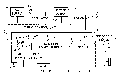
Referring to Figure 1 where the initiating system is
25 generally depicted, three separate components designated 1, 2
and 3 are shown. Component 1, labelled the "Firing Control
Unit", comprises a power supply 5 with associated oscillator
6 and power output 7. A pulsed electrical signal is
delivered from the control unit 1 through switch 101 via
30 conductors 4 and rectifier bridge 8 to component 2 which is
the "Photo-Coupled Firing Circuitn. Conductors 4 provide
power for a first light source 9 and a second light source
15. The first light source 9 can comprise a lightbulb for
generating light energy. The second light source 15 may
35 comprise, for example, a light emitting diode (LED) for
-
1 326063 C-I-L 730
--6--
optical coupling and control purposes as will be discussed
below.
Component 2 comprises a iring arrangement including a
means 11 for processing the electrical energy, a means 12 for
storing the electrical energy, and a firing circuit 13.
Attached to the input of the means for processing electrical
energy is a means for receiving light energy and converting
it to electrical energy, comprising, for example, a
photovoltaic cell 10 and a light detector 16 which may
10 comprise a photodiode. Photovoltaic cell 10 is positioned to
receive pulsating light energy from the lightbulb 9 and the
light detector 16 is positioned to receive a pulsating light
signal from the light source 15.
Component 3, labelled "Disposable Device" comprises the
15 initiation unit itself and consists of a squib 17, a shock
wave conductor lead-in line 18 and a detonator 19. The
squib 17, which provides firing energy for the detonator 19,
is adapted for plug-in connection with firing circuit 13 of
component 2.
Referring to Figure 2, pulsed electrical signal carried
by conductors 4 is delivered to light bulb 9 and LED 15. The
light energy generated by lightbulb 9 is received by the
means for receiving the light energy and converting it to
electrical energy. In the illustrated embodiment, this
25 comprises the solar cell 10. The light energy from LED 15 is
received by photodiode 16. Thus, solar cell 10 is disposed
to receive light from lamp 9, and photodiode 16 is disposed
to receive light from LED 15.
The switching power supply generally designed 11 for
30 processing the converted electrical energy comprises an
inductor 24 and transistor 30 in conjunction with
photovoltaic cell 10 and light detector 16. Means 11 also
includes a security circuit which rejects low frequencies and
discharges capacitor 12 in the event of interruption or
35 absence of the correct coded signal. The security circuit
- 1 326068
C-I-L 730
--7--
includes diodes 65 and 66, capacitor 31, resistors 32, 33 and
34 and inverters 28 and 29. The means for storing the
process electrical energy comprises a capacitor 12. A diode
25 is shown between inductor 24 and capacitor 12.
The firing or triggering circuit generally designated 13
comprises zener diode 37 connected to a high current solid
state switch such as a power mos field effect transistor 45.
Connected between the zener diode 37 and the field effect
transistor 45 are transistors 40 and 39. Resistors are shown
10 at 38, 41, 42, 43 and 44.
In operation, when the positive going portion of the
pulse train is applied to the lightbulb 9 and the LED 15,
both the lightbulb and the LED will be illuminated. Light
energy, generated by the lightbulb 9, will be transmitted to
15 the solar cell 10, and the light signal, generated by the LED
15, will be transmitted to the photodector 16. The light
energy, received by the solar cell 10, is converted to
electrical energy by solar cell 10. When LED 15 is ON, and
photodetector 16 is also ON, transistor 30 is turned ON.
20 Accordingly there is a low impedance discharge path for the
solar cell 10 through the inductor, so that the electrical
energy is stored in the inductor when LED 15 is turned ON.
When the zero level or negative going portion of the
pulse train is applied to the lightbulb 9 and LED 15, both of
25 these light sources are turned OFF. Accordingly, no further
light energy is transmitted to the solar cell 10, and
photodetector 16 ls turned OFF. With photodetector 16 turned
OFF, transistor 30 is turned OFF. The energy stored in the
inductor is released as a voltage spike in the order of 10 to
30 15 volts which charges the capacitor 12 through the diode 25.
A portion of the charging energy will also be applied to the
capacitor 31 through diodes 65 and 66.
Although a voltage spike of 10 to 15 volts is produced,
the capacitor will not charge up to that voltage level.
35 Instead, several cycles will be required for the capacitor 12
-
ii 1 326068
C-I-L 730
--8--
to charge up to the level of 9 volts. In one specific
example, approximately seven seconds were needed to charge a
260 microfarad capacitor at a frequency of 3 KHz and a duty
cycle of 90% on time and 10~ off time.
When capacitor 12 is charged to a level of 9 volts,
zener diode 37 is turned ON so that current can flow through
the resistor 41. The resulting voltage drop across resistor
41 will provide a signal to the transistor 4~ which in
conjuntion with transistor 39, provides an amplified signal
10 to turn on the high current solid state switch 45. The
current from capacitor 12 is then allowed to flow through the
ignition resistor ~8. A small portion of this current will
also flow through shunt resistor 67.
It can be seen that the zener diode 37 senses when the
15 capacitor 12 has reached the firing voltage, whereupon it
provides a path for current from the capacitor 12 to ignite
the squib 17 (Fig. 1). Detonator 19 is ignited by energy
carried from electrically-ignited squib 17 by means of a
shock wave conductor 18.
The system as above described operates only within a
given range of frequencies and duty cycles. If the frequency
is too low, then capacitor 31 will not charge up.
Accordingly, inverter 29 will provide a low impedance
discharge path for capacitor 12. The upper frequency of
25 operation is limited by both the frequency response of the
photodetector 16 and the time constant of the inductor
circuit.
The pulsating light source must have the correct duty
cycle at the correct frequency in order to activate the
30 charging circuit for capacitor 12. The duty cycle is defined
as the percentage of time in each cycle during which the
light remains ON. A minimum on time and a minimum off time
is required to store the energy in the inductor and release
it.
Thus, the system is "codedn. Specifically, unless the
` 1 326068 C-I-L 730
_ g _
right type of signal is provided to the lightbulb 9 and the
LED 15~ firing energy will not be provided to the ignition
resistor.
The requirement that several cycles are needed to drive
the voltage on capacitor 12 up to the firing voltge is an
advantage in safety in that a waiting period is provided
during which time the circuit can be deactivated by removal
of the "coded" signal.
Transistors 40 and 39 are provided for speeding up the
10 firing of the field effect transistor 45.
The system will not be set off by stray fields or by
randomly transmitted radio waves. The energy from the light
generator is coupled optically to the firing circuit so that
it will not be affected by such stray fields or randomly
15 transmitted radio waves.
Referring to Figure 3, the firing control unit comprises
a means for generating a pulse train. In the embodiment
shown, the means for generating a pulse train comprises an
astable multivibrator 6 whose output is fed to the base of
20 transistor 48. The output of the transistor 48 is fed to
rectifier bridge 8 (Fig. 2) whose output drives both the
lightbulb 9 and the light source 15. The frequency and duty
cycle of the pulse generator are determined by the selected
values of capacitor 50, resistor 54 and resistor 61.
Although not specifically depicted, a further useful
feature of the invention is the addition of current
regulation to the photo-coupled firing unit identified as 2
in Figure 1. This feature improves power distribution in
large centralized blasting operations by permitting
30 initiation of explosive charges at many blasting locations
which are separated from each other by long lengths of
initiating wire. The device typically draws 100 milliamps
and can operaté on standard wire sizes up to distances of
five miles.
Although not specifically depicted, a still further
--~ 1 326068
C-I-L 730
--10--
useful feature of the invention is the addition of a "firing
signal" to the said coded signal. This feature provides the
advantage of accurate timing of multiple blast holes and can
be used to initiate a large number of detonators
simultaneously or provide synchronization for electronic
timing counters which counters can introduce discrete time
delays between blast holes. The means for coding the optical
signal need not be limited to electrical means but may
include, for example, the use of different wave lengths which
10 can be decoded through difraction or other electronic means.
It is envisioned that miniaturization techniques may
allow the Photo-Coupled Firing Circuit and the Disposable
Device to be combined into a single integrated device. Such
a device might be enclosed for example, within the confines
15 of a specially adapted detonator.
Although a particular embodiment has been described,
this was for the purpose of illustrating, but not limiting,
the invention. The two light sources and two light receivers
described in the preferred embodiment can be replaced with
20 one light source and one receiver if, for example, the energy
requirements of the system are low or if higher efficiency
light emitters and receivers are employed.
Various modifications or component substitutions such as
LASER diodes or commercially available opto-isolators, which
25 will come readily to the mind of one skilled in the art, are
within the scope of the invention as defined in the appended
claims.