Note: Descriptions are shown in the official language in which they were submitted.
1 326402
DIE PROTECTION ASSEMBLY FOR PREVENTING FRAUDULENT
: PRINTING BY AN ELECTRONIC POSTAGE METER
RELATED PATENTS
Other patents which describe and claim related
5subject matter are U.s. Patents 4,876,956 and 4,953,996.
; FIELD OF THE INVENTION
The invention relates to electronic postage meters
and more particularly to so-called flat-bed printing
meters.
10BACKGROUND OF THE INVENTION
Electronic meters of the flat-bed printer type are
well-known and are described for example in U.S. Patent
No. 4,579,054, issued to Buan, et al, which shows a
stand-alone electronic mailing machine in which the
electronic postage meter forms an integral part of the
device. Other aspects of such a stand-alone mailing
machine are described in U.S. Patents 4,535,407 and
4,523,523 among others.
of particular concern in postage meters and mailing
machines is the prevention of unauthorized printing of a
meter impression. That is, since the printing of the
impression assumes that the Post Office has been paid
for the delivery of the mailpiece, the making or
"wiping" of a print without accounting for the value
will result in loss of revenue to the Post Office to
cover the costs of delivery. It will be appreciated
that in an area of such concern, many devices have been
developed to solve problems associated with the security
of the printing die.
30Die protection assemblies incorporate various
mechanical arms or projections which protrude from the
printwheel area of the die in order to prevent a person
'~
, ~ - ." , . ~ ,
r
1 326402
; 2
from simply placing an envelope against the die to
obtain an imprint.
U.S. Patent No. 2,795,186 issued to Bach shows a
movable shroud which can be lowered to guard the
printing die against taking unauthorized impressions at
any time between printing operations. The shroud
completely covers the face of the value printing die
- when the printing mechanism is not in an operating
cycle and is locked in that position until the cycle
` 10 starts at which time the shroud moves to a position
uncovering the die. U.S. Patent No. 4,559,444 issued
to Erwin et al. teaches an interposer arrangement which
extends upward from the platen into the space into which
an envelope or other workpiece is to be inserted. These
interposers are moved out of the way during a
legitimate printing operation. The interposer blades
are mechanically linked to the inking mechanism in order
to move the blades out of the way as the mailpiece moves
into position for imprinting. U.S. Patents 4,796,526
and 4,796,527 describe interposer devices which are
` linked to the motor driving the platen of the printer to
move out of the way or actuated by a power switch to be
moved out of the way so long as power is applied to the
machine.
While these known devices work well in the
particular environments in which the platen and the die
are not expected to be physically separated, in a
modular device where the meter with its secure die is
removable from the assembly where the platen is
retained, several new security issues are created in
respect of a flat-bed printer type of postage meter.
SUMMARY OF THE INVENTION
The electronic meter in accordance with the invention
1 326402
-- 3 --
is a flat-bed letter press printing postage meter which is
removable from the mailing machine and in which there are
included novel die protection features to protect the die
when the meter is removed and the platen remains with the
mailing machine or base.
In a preferred embodiment, the postage meter in
accordance with the invention has three independent die
protection mechanisms to prevent the fraudulent "wiping" of
prints. For best results, the meter will not actually
print, it will rather allow prints to be taken by the
mailing machine during a narrow time "window" when all of
the meter die protection is withdrawn.
In accordance with the invention, the first die
protector comprises a sliding plate which completely covers
the printing elements when the meter is removed from the
mailing machine. In a preferred embodiment, this plate
cannot be retracted unless the meter is in place on a
legitimate mailing machine. The second protector device
comprises die protector blades or interposers which are
adjacent to two of the printwheels, preferably the higher
order printwheels. They are locked into a position which
causes them to protrude beyond the print surface anytime a
retracting solenoid is unpowered. This mechanism protects
the die from print "wiping" anytime the meter is not
enabled and ready to print. The third protector mechanism,
called herein the aligner/protector mechanism, is similar
to this second, but it is separately actuated, and is
locked in place at all times except for a time controlled
"window" when printing takes place. It is anticipated that
accounting for postage would occur at the start of each
such "window".
When the meter is removed from its machine, all three
die protection mechanisms are unconditionally in place, and
die access is not possible for printing or any other
purpose. After installation on the machine, die protection
is selectively removed as follows:
1.) Successful installation retracts the die cover
plate;
4 l 326402
2.) When printing eligibility conditions are
satisfied, that is, where there is adequate power and
sufficient funds and the like, the die protector blades
are retracted; and finally,
3.) The aligner/protector blades are momentarily
withdrawn only at the time of each accounting if the
necessary conditions are satisfied.
When properly installed on the mailing machine,
during all normal operations, the meter is in commun-
ication with the mailing machine via a communications
channel. In a preferred embodiment, the mailing machine
will communicate a request that the meter raise its die
protectors/aligners so that a print may be taken, and
that a disable or "locked out" meter can reject the
request and prevent any attempts at printing.
Other aspects of this invention are as follows:
In a postage meter having a print die which
includes printing elements for printing postal value, a
die protector arrangement comprising:
die protector blades disposed adjacent said
printing elements and normally extending outwardly
beyond a printing plane defined by said die and said
printing elements, said protector blades being locked
for preventing proper printing whenever the blades are
in such extended position;
a first plurality of said die protector blades
being retracted when at least a first condition has
occurred; and
the remainder of said die protector blades being
retracted when at least a second condition different
from said first condition has occurred while said first
plurality of die protector blades are retracted whereby
proper printing is enabled by the retraction of all of
the die protector blades when said first and said second
conditions have occurred.
A
.
1 326402
4a
An electronic postage meter having a print die and
printwheels thereon for printing of value, the printing
of value and accounting thereof being controlled by at
least one microprocessor, the improvement comprising a
die protector mechanism under microprocessor control
which includes:
die protector blades disposed adjacent said
printing elements and normally extending outwardly
beyond a printing plane defined by said die and said
printing elements, said protector blades being locked
for preventing proper printing whenever the blades are
in such extended position;
a first plurality of said die protector blades
being retracted under control of said microprocessor
when first conditions including no meter malfunction
have been tested; and
the remainder of said die protector blades being
retracted when a request for print signal occurs while
said first plurality of die protector blades are
retracted whereby proper printing is enabled by the
retraction of the die protector blades.
BRIEF DESCRIPTION OF THE DRAWINGS
Fig. 1 is an external perspective view of an
electronic meter in accordance with the invention.
Fig. 2A is a perspective view of a meter in
accordance with the invention shown in position on a
mailing machine.
Fig. 2B shows one way of removing a meter in
accordance with the invention from the mailing machine.
Fig. 3 is a bottom view of the meter which shows
the sliding shutter that covers the die when the meter
is removed from the mailing machine
Fig. 4A is a perspective view showing the print
die and solenoid-operated dead bolt with the sliding
shutter in the closed position. Other meter internal
assemblies except for the die are not shown for ease of
viewing.
A
1 326~02
4b
Fig. 4B is a similar perspective view of the meter
as in Fig. 4A showing the sliding shutter in its
retracted position.
Fig. 5 is a side view of a first embodiment of an
operate-remove mechanism for attachment of the meter to
the mailing machine.
Fig. 6 is a side view of an alternative embodiment
of an operate-remove mechanism.
5 1 326402
Fig. 7 is a partially exploded view of a suitable
internal configuration of the meter in accordance with the
invention.
Fig. 8 is a functional block diagram of a
5computerized postage meter.
Fig. 9 is a block diagram showing communication
between the mailing machine and the postage meter.
Fig. 10 is a flow chart of a suitable communication
routine for releasing the dead bolt to allow retraction of
10the sliding plate.
Fig. 11 is a side view of the printwheel setting
mechanism in the postage meter.
` Fig. 12 is a section taken along the line 12-12 of
Fig. 11.
15Fig. 13 is a section taken along the line 13-13 of
Fig. 11.
Fig. 14 is a section taken along the line 14-14 of
Fig. 11.
Fig. 15 is an embodiment of a die protector
20arrangement in which the die protectors are disposed
adjacent to the higher order printwheels.
i Fig. 16 shows an embodiment wherein there is an
aligner/protector mechanism for the lower order
printwheels.
25Fig. 17 is a flow chart for the operation of the die
protector blades for the higher order printwheels.
Fig. 18 is a flow chart for the operation of the
aligner/protector blades.
Figs. l9A - l9H comprise a flow chart for the
30operation of the printwheel setting mechanism.
DETAILED DESCRIPTION OF THE DRAWINGS
In Fig. 1 there is shown at 10 an electronic meter in
accordance with the invention. The cover 12 of the housing
14 holds a keyboard and display 16. The keyboard and
35display are suitably similar to that shown in U.S. Patent
4,097,923 specifically incorporated herein by reference.
Preferably, the keyboard is of conventional monolithic type
and the display is liquid crystal with a capacity of twelve
: . -
- 6 - l 32 6 4 02
digits. It will be understood that the meter keys and
display of registers are not necessarily limited to those
shown in this reference and may be varied as desired in
accordance with the requirements of the meter. When the
meter 10 is installed on a mailing machine, the keyboard
and display may be hidden from view of the operator.
Fig. 2A is a perspective view of the meter 10
installed in a mailing machine or meter base 18. The
mailing machine 18 has schematically shown therein a
printing platen 20 reciprocally driven by motor 22 through
rack and pinion mechanism 24. Lid 26 when closed during
normal operation will cover the meter. Feeder module 28
feeds mailpieces to the base 18 which transports the
mailpiece to the space between the print die 30 of the
meter which carries the meter indicia and the platen 20,
whereupon with upward reciprocation of the platen, an
imprint of the indicia is placed upon a mailpiece such as
mailpiece 32 shown being ejected from the mailing machine.
Platen drive arrangements are well known and are
shown for example in U.S. 4,579,054 to Buan et al. and in
U.S. 2,795,186 to Bach et al. It should be appreciated
however that in respect of the meter in accordance with the
invention the platen 20 is a part of the base 18 and the
meter 10 includes only the print die 30. The mailing
machine will not be further described except as necessary
for the description of the operation of the meter 10.
In the preferred embodiment the print die is an
elastomer print die in order to obtain the best print
quality for a given platen force. It will also be
appreciated as is well-known that the print die must be
inked in order to print the indicia. Inking mechanisms are
known and are also shown in the previously cited patents of
Buan and Bach. Preferably the inker mechanism (which is
not shown) also remains with the base 18. It will be
understood that the inker could be a part of the meter
instead.
Fig. 2B shows the meter being removably mounted on
the base 18. The meter is inserted into pocket 34 which is
pivotally mounted to the base 18. When the meter is
- 7 - l 32 6 4 ~
inserted into the pocket 34 connector 36 in the pocket
mates with a corresponding connector 38 (not shown in Fig.
2B) on the meter 10.
The mating connectors 36 and 38 serve to enable
communication between the mailing machine 18 and the meter
10 and preferably carry power to the meter as well. A
suitable communication system is described in U.S.
4,301,507 issued to Soderberg et al specifically
incorporated herein by reference. The communication
between the units as described in this patent is serial
character asynchronous, bit synchronous, in message form,
with the bits of the messages being timed in accordance
with a given schedule for synchronous control. It will be
understood that other communication procedures and devices
well-known in the art may be used in the alternative if
desired.
Turning now to Fig. 3 which shows a bottom view of
the meter, a sliding plate or shutter 40 is slidingly
mounted on housing 12 and is locked in the illustrated
closed position suitably by means of dead bolt 42,
preferably spring-loaded, which extends into the hole 44 of
shutter 40. The shutter is released by actuation of
solenoid 46 (seen in the illustrated embodiment of Fig.4A
and 4B) but it will be understood that means such as a
cam-actuated, motor-controlled locking mechanism may be
used in the alternative or in addition to such solenoid-
actuated deadbolt if desired.
Fig. 4A and 4B show perspective views of the meter
with the shutter 40 shown covering the print die 30 and in
the retracted position with the print die exposed.
In order to prevent access to deadbolt 42 from the
outside, it will be understood that hole 44 may be a blind
hole or bore on the inside of the shutter 40.
As previously noted, the meter in accordance with the
invention is a flat bed printer with elastomer printing
dies and that the platen and inking mechanism preferably
remain with the mailing machine. In order to protect the
print die in this configuration, whenever the meter is
removed from the mailing machine, in accordance with the
- 8 _ l 32 ~4 02
invention all of the printing elements are automatically
covered by the shutter 40. This shutter which covers the
die is only retracted as discussed below when the meter is
in place on a legitimate mailing machine. The die cover or
shutter 40 is one of three independent die protection
mechanisms in this meter.
It should thus be appreciated that the die would
still be protected from the "wiping" or fraudulent taking
of prints by the other protection mechanisms. Exposure of
the print die 30 however might still allow tampering to
alter some of the artwork of the indicia or allow damage to
occur or to expose the operator to ink from the die.
Fig. 5 is a side view of one embodiment of an
operate-remove mechanism for the meter. Carry handle 48
(not shown in previous Figures) is pivotally mounted on
meter 10 at pin 50. Slot 52 on the handle is operative to
engage a mating pin (not shown) on the base 18 when the
meter is pivoted downward as illustrated in Fig. 5 and the
` handle 48 is rotated in the clockwise direction. It will
c 20 be understood that at this juncture the meter 10 is
electrica'ly connected to the meter base 18 through mating
connectors 36 and 38 and is locked to the base by slot 52
engaging with the mating pin on the base.
With the meter and base operative, communication is
established and using appropriate "handshake" messages
between the meter and the base it is determined that a
proper meter is in the home position on a legitimate base.
Accordingly, deadbolt 42 (not shown in Fig. 5) is
retracted, preferably only for a predetermined length of
time. With the deadbolt retracted, the shutter 40 may be
moved rearward (to the right in Fig. 5). In the
illustrated embodiment, this is accomplished by means of
the flexible cable 54 having handle 56 for grasping by the
operator. The cable is sui~ably mounted on the pocket 34
by any convenient means (not shown). The other end of the
cable is connected to pull slide 58 slideably mounted on
the base 18 by any convenient means (also not shown). The
side wall 60 carries pin 62 and pin 64. With the meter in
the home position, that is in the lower position
- 9 13~64~2
illustrated, pin 62 engages slot 66 of slide pull 58. When
the slide pull 58 is moved by the operator pulling forward
on the flexible cable, the shutter 40 will also be
retracted to uncover the print die shown at 30.
As shutter 40 moves, pin 64 will interlock with slot
66 of the carry handle 48 to prevent the meter from being
lifted from the operating position when the shutter is
retracted. Thus in order to remove the meter 10, The
operator must push the flexible cable inward to push the
shutter 40 into position again covering the print die 30.
The deadbolt 42 is spring-loaded and re-engages the hole 42
in the shutter to lock the shutter in secure position.
Other methods and apparatus may be used for the
purpose of retracting the shutter. Fig. 6 shows an
alternative embodiment where the meter is installed by
lowering it vertically into the base. In Fig. 6 the
mechanism is shown in mid-position after the meter has been
installed and locked in position but prior to the
retraction of the shutter mechanism.
The meter shown in this embodiment is placed
vertically downward on the base with square pin 100 on the
meter being to the front of the meter and pin 110 on handle
120 clear for up and down movement of the meter from the
base. The cam surface 130 on the meter captures the pin
110 and as the lever is pulled by the operator toward the
front of the meter the vertical slot portion of the cam
surface 130 is pushed toward the operator so that pin 100
is engaged in slot 140. At this point the meter is locked
in place and communication between the meter and the base
is established as described in connection with Fig. 5.
With the appropriate "handshake" the deadbolt is raised to
allow further movement of the handle. Pin 160 which is
mounted on the shutter has also moved into contact with
wall 170. Preferably, a lip or angled member shown at 200
also engages a slot 210 to lock the meter to the base.
As the handle 120 moves further forward, sector 220
engages pinion 230 which drives rack 240 affixed to member
260 that carries wall 170. The shutter plate is moved
rearwardly by action of wall 170 on pin 160 until the
lO ~ 3~6~0~
handle is stopped by the cam surface 130 and the shutter
has exposed the print die.
Other means for locking the meter in place and for
actuating the retraction of the shutter can be envisioned
depending in part on the way the meter is required to be
installed. It will be understood that the various
operations for retracting the shutter described herein as
performed by the operator can be motorized if desired.
Fig. 7 shows a partially exploded view of a meter in
accordance with the invention. The meter 10 is shown with
the cover 12 and keyboard and display rais~d from the
bottom to expose a schematic layout of the meter hardware.
The connector 38 feeds into the printed circuit boards 300
which comprise the accounting and printing control
functions described below. The print wheels 310 are set by
stepping motors 320 in an arrangement also described
below. A dater assembly 330, PIN counter 340 and a slogan
printer 350 are also provided as required. Preferably, a
door 360 provides access as necessary to the slogan, PIN,
and date printers.
Fig. 8 is a functional block diagram of a
computerized postage meter. The system is controlled by a
microprocessor which basically comprises a CPU which
performs ~he functions of accounting, controlling the
setting of the printwheels, die protection and the
communication with the base and other peripherals as
required. Three types of memory units are employed with
the CPU. The permanent memory PM which may be a ROM or
PROM stores the sequence of program operations to be
performed by the CPU for its accounting calculations and
control functions. The temporary memory TM which is a
working RAM holds the data and calculation results on a
temporary basis until they are stored in the non volatile
memory NVM. The non volatile memory can be battery-backed
RAM, EEPROM, EAROM, or MNOS as desired or any combination
if two or more memories are utilized. Preferably, at least
two nonvolatile memories are used and transac~ion
accounting data is stored in nonvolatile memory for each
transaction. A suitable method for such accounting is
- 11 1 32640~
shown in U.S. Patent No. 4,484,307. Other accounting
methods are described in U.S. Patent No. 3,978,457. Funds
may also be placed in or removed from memory by means as
described in U.S. Patent No. 4,097,923 specifically
S incorporated herein by reference.
The system in accordance with the invention may
operate in accordance with data input through the keyboard
and display 16 and displays information on the same or it
receives and transmits information to the mailing machine
or other peripheral through connector 38 as shown in Fig.
9. The meter keyboard and display in a preferred
embodiment would be useable only for the purpose of reading
the various meter registers and/or for the purpose of
refunding the meter and for various checks and accounting
operations which may be required when the meter is not
installed on its base. When the meter is installed on the
base, the CPU in accordance with the data it receives from
the base, operates the stepping motors 320 for setting the
printwheels 310 shown in this Figure as the setting postage
block SP and also controls the other die protector devices
to allow the printing of postage to take place. These
operations are indicated at the postage printing block PP.
Fig. 9 shows a block diagram of the communication
between the meter and mailing machine. As mentioned
previously it is preferred that all the communication be by
way of the protocol described in U.S. 4,301,507.
Fig. 10 is a flow chart for the releasing of the
deadbolt 42 to allow the shutter to be retracted. Once it
has been determined that the meter is on an appropriate
base, the solenoid is actuated for a predetermined amount
of time to allow the operator to move the shutter.
Figs. 11-14 show the printwheel setting mechanism.
The printwheel setting mechanism comprises five motor
driven gear trains. Five stepper motors (each designated
320 since the drive trains are similar for each printwheel)
are mounted on walls 400 each motor respectively driving an
associated printwheel 310 via respective motor pinions 410,
encoder assembly gears 420, transfer gears 430, and
printwheel gears 440 attached to the-printwheels 310. Each
~ 32640~
- 12 -
gear train includes a two-channel encoder sensor assembly
designated herein as 480. The encoder assembly gears 420,
suitably of molded plastic, include ten (10)-tooth gears
which mesh with the transfer gears 430 and twenty
(20)-tooth gears that mesh with the motor pinions 410 along
with the planar wheel portions which extend into the sensor
assemblies 480.
Each sensor channel comprises a source, suitably an
infrared-emitting diode and a detector, a photodiode with
lo its associated circuitry. Such sensors are conventional
and will not be further described.
Preferably the encoder wheel operates to produce ten
(10) transitions per revolution as the encoder wheel passes
through the sensor assembly and in each sensor channel
alternately blocks and unblocks the radiation from the
source. This results in two (2) sensor detector
transitions (one for each channel of the two-channel
sensor) for each move of one-digit.
The channels are physically separated such that as
the encoder wheel rotates the detector outputs are in phase
quadrature (the output of one of the two detectors leads or
lags the output of the other detector by one quarter of a
cycle).
The motor pinions 410 are twelve (12) tooth gears
affixed to the motor shafts and mesh with the twenty (20)
tooth gears of the encoder gear 420.
The stepper motors 320 turn through a complete
revolution in 24 steps which, as transmitted through the
gear train previously described, require 4 motor steps for
movement of one digit of the printwheel. In this
embodiment, the stepper motors are four-phase motors
preferably driven by the drivers in a two-phase mode. The
motor control sequence is discussed below in conjunction
with the flow charts for the printwheel setting.
Each printwheel 320 is suitably a plastic component
which forms a substrate for the molded rubber print
characters located around the periphery of the wheel, one
of which is designated 450. The printwheel also comprises
ten (10)-tooth printwheel gear 440 which is used also as
described below for alignment of ~h3e printwheel when
printing takes place.
It will be understood that the setting mechanism
further accommodates shifting of the decimal point between
the middle digit printwheels and the least significant
digit printwheel to obtain various postal values as
required.
The transfer gears 430 are thirty (30)-tooth gears,
suitably of molded plastic, that mesh with the printwheels
gears 440 and the ten (10)-tooth gears of the encoder gears
420. The transfer gears 430 include a protrusion 460 which
in conjunction with a fixed feature 470 on the housing
provides an end stop or zero-reference position for the
mechanism.
When the trans~er gear protrusion 460 is adjacent the
stop 470 that there is a known fixed value on the print die
plane. It will be appreciated that with thirty (30) teeth
on the transfer gear meshing with the ten (10)-teeth on the
printwheel gear there will be three (3) rotations of the
printwheels for one rotation of the transfer gear. Because
of the particular implementation of the end stop, there are
in this embodiment twenty-six (26) transfer gear positions
which correspond to the 10 digit position of the
printwheel. In accordance with the invention, advantage is
taken of the fact that a particular digit setting is
available at a plurality of transfer gear positions in
order to achieve the shortest path movement of the transfer
gear to achieve setting of ~he required character on each
printwheel.
In the embodiment shown in these Figures, a single
solenoid 490 raises die protector blades 495 in tandem to
enable the printing of postage. While this arrangement
normally works well in conventional flat bed printers,
there is further provided in the postage meter in
accordance with the present invention further die
protection as shown more particularly in conjunction with
Figs. lS and 16.
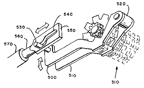
Fig. 15 is a perspective view of the die protector
mechanism. In accordance with the present invention, two
,~ :
1 32640~
- 14 -
die protector blades 500 and 510 are placed adjacent to the
two highest order printwheels of the printwheel banks 310.
When the meter is logically incapable of accepting a print
request, these two blades protrude beyond the printing
plane of the print elements to prevent the "wiping" of
fraudulent prints from the die.
Particular conditions under which, for example, the
meter may be disabled include lack of power, insufficient
funds, value selection in progress in which the higher
order printwheels are to be moved, and various sensed error
conditions.
As is shown in Fig. 15, blades 500 and 510 are
pivotally attached at shaft 520 and at the opposite end are
engaged via pin 530 which is held in S-shaped slot 540 of
member 550 to the armature 560 of solenoid 570. The
solenoid 570 is under the direct control of the
microprocessor. When the solenoid is energized it pulls in
the member 550 against the force of a spring (not shown)
and the elevated portion of slot 540 raises the die
protector blades. The die protector blades will remain
retracted until the microprocessor de-energizes the
solenoid or until power is lost. When the die protector
blades are retracted, they perform the alternate function
of detenting the two higher order print wheels to improve
their alignment.
Fig. 16 shows an additional die protector mechanism
which comprise a set of protruding die protector blades,
called here aligner/protector blades which are retracted
for only a brief interval during each print operation.
Preferably this retraction coincides with the meter
accounting operation. In accordance with the invention,
these aligner/protector blades shown at 600, 610, and 620
are disposed next to the lower order printwheels. The
three blades are normally locked in position as shown
suitably by projecting tooth 630 of rotatable cam 640.
Solenoid 650 when actuated rotates cam 640 to move tooth
630 out of the way and to raise the aligner protectors by
engagement of the tooth 660 on cam 640 with tooth 670 on
the die protector blades. The rotation of cam 640 is also
- 15 - ~3~640~
against a spring (not shown) so that in the event of
failure the cam will return to the locked position.
It wlll be appreciated that the actuation of these
two types of die protection may be by way of either type of
mechanism described herein and is not limited to either
method so long as the locking is achieved.
For operation, the three blades are normally locked
in the protruding position and external forces cannot cause
them to retract. When the mailing machine communicates a
request to print an imprint, the meter will consider the
request and on the basis of availability of funds and other
printing criteria, and if accepted will energize the
solenoid and withdraw the aligner/protectors for a timed
period in which the mailing machine can ink the die and
take the print. Preferably, the aligner/protectors have
the auxiliary function of detenting and aligning the lower
order printwheels.
Figs. 17 and 18 are flow charts for the operation of
the die protector and the aligner/protector mechanisms.
The operation of each has been described and it is not
believed to be necessary to describe the flow charts in any
greater detail.
Figs. l9A l9H show the operation of the print wheel
setting mechanism shown and described in conjunction with
Figs 11-14. The flow chart shows the operation of the
mechanism to enable advantage to be taken of the shortest
path to the new setting. This is of great benefit to the
increased setting speed required for the throughput of a
meter in accordance with the invention for minimizing power
consumption.
Fig. l9A shows the normal set postage routine for
setting the printwheels of the postage meter. In
accordance with this routine, a success flag is first
cleared and a flag indicating whether the position of the
printwheels is known is checked. If the position-known
flag is set, a software initialization routine is called.
A subroutine SDIGITS calculates the digit distance for all
five banks of printwheels and when this calculation is
complete a set postage routine, ~STEP, is called. At the
.
- 16 _ ~ 32 64~2
' end of the setting routine, the position is again checked
and if it is known the success flag is set.
Fig. l9B shows the subroutine SDIGITS which computes
the distance and direction that each digit wheel must move
by subtracting the value of postage currently set, stored
as old value from the desired value stored as new value.
j As mentioned in the discussion of Figs. 11 through 14, each
printwheel character printing position is associated with
multiple transfer gear setting positions. Thus in
accordance with the routine, except when the meter setting
mechanism is being initialized, ten (10) is added to the
new digit to place the new number in the center decade of
the transfer wheel. The value presently set in tne
printwheel is subtracted from the new value thus obtained
to get the difference (DIFF). The sign resulting from the
subtraction is also stored to determine the direction the
printwheels must move.
A test is then made as to whether initialization is
being done. If yes, the routine returns to the main loop.
If initialization is not being done, the DIFF is tested to
see whether it is greater than five (5). If DIFF is equal
to or less than five (5) the program returns to the main
loop. If the outcome of a test shows that the difference
is greater than five (5), DIFF is tested again for being
greater than, equal to, or less than ten (10). If the
outcome is equal to ten (10), DIFF is made equal to zero
(0) and the program returns to the main loop. If greater
than ten (10), ten (10) is subtracted from the difference
and the result is again tested. If DIFF then is less than
ten (10), the direction is tested to see whether the
printwheels are to move up or down.
If the wheel is to move up, the set value plus (ten
minus DIFF) is tested and if less than or equal to
twenty-six (26), the direction is reversed and DIFF is set
equal to ten (10) minus DIFF. If no, the program returns
to the main loop.
If the printwheel direction is down, then set value
minus (10 minus DIFF) is tested as being greater than or
equal to zero (0) and if it is then direction is reversed
- 17 - 1 32 640~
and DIFF is set equal to ten (10) minus DIFF. If no, the
program returns to the main loop.
Fig. l9C shows the subroutine SSTEP. This subroutine
will move the printing wheels by the number of digits
specified in the SDIGITS program and in the direction
specified in that subroutine. In this subroutine, the
position known flag is cleared and the number of motor
steps required are calculated by multiplying the digit
distance by four (4) since the stepper motor moves four (4)
steps for each digit. The wheel position in sensor
transition is also calculated as two (2) times the set
value. This is determined for each bank. At this
juncture, the subroutine SMO~OR is called to provide the
step pulses to the stepper motor to drive the printwheels.
The digit wheel position is calculated from the wheel
position in sensor transitions which have been kept updated
through the move, divided by two (2), since as mentioned
previously there are two (2) sensor transitions per digit.
The calculation is checked to see if its an exact multiple
of two (2) and if not, an error routine is called. If yes,
the set value is stored. A routine then follows to check
whether the setting is initializing and if not, the print
value is set equal to the set value. The print value is
checked to determine whether it is greater than or equal to
ten (10), if it is, the print value is made equal to the
print value minus ten (10) and again checked.
If the print value is less than ten (10), the routine
proceeds to check whether the print value now equals the
new value and if not, an error routine is called. If the
answer is yes, the subroutine determines if there are any
remaining banks to be set. If there are, the wheel
position for the next bank is checked until no banks remain
to be checked. The position known flag is se~ before
returning.
Fig. l9D shows the subroutine SMOTOR for providing
step pulses to each motor. Each motor is provided output
on a sequential basis during the setting cycle for the
printwheel banks. For each bank then the motor steps are
checked and if they are greater than zero (0) then an
.
- 18 - ~ 32 6 4 02
output is set for the motor to move one (1) step and an
"output ready" flag and "waiting for timer" flag are set.
The sensor monitoring routine SSENDS is called and a check
is made as to whether another bank is required to he set.
If at the check for motor steps, the bank shows zero
(0) steps to do, the program branches to set up data for
present position holding coil and a holding counter is
decremented. If the counter has not reached zero (0) the
program returns to the main loop of SMOTOR and the "output
ready" flag and "waiting for timer" flags are set and the
sensor monitoring routine is again called. If the counter
has decremented to zero (0), then the flag is set for
zero (0) and the "waiting for timer" flag is set with no
"output ready" flag. The program operates until all the
zero (0) flags are set at which point it returns to the
main loop.
Fig. l9E shows the subroutine SSENDS which monitors
the sensor channels to update the actual positions of the
wheel. In this subroutine, each bank sensor is read and it
is determined whether a transition has been made. If the
answer is yes, the direction is determined by checking the
transition sequence of the two channel sensor and if the
direction is down, one is subtracted from the wheel
position and if the direction is up, one is added to the
wheel position. At this point the "waiting for timer" flag
is checked and if it is clear the program returns. If the
waiting for timer flag is not cleared then the next bank is
read.
If no transitions were detected then the "waiting for
timer" flag clear is checked. And if cleared, the program
returns.
Fig. l9F shows the timer interrupt routine.
Fig. l9G shows the subroutine for initializing the
printwheels. In this routine, the new value is set equal
to twenty-six (26) for each wheel and the transfer gear is
driven all the way to the stop. At this point, the
"position known" flag is checked and if the "position
known" flag is not set, the set value is set equal to all
1 3 2 6 4 0 2
zeros (0's). If the position known flag is set, the step
of making all zeros (0's) is skipped.
The initialization flag is then set, the common
initialization routine is called and the subroutine
proceeds to check the printwheel positions at the middle
and opposite end. At this point, the current set postage
is set equal to zero (0) and the position known is tested
and if the position is known, the success flag is set. If
not, the success flag is not set and in both instances the
program returns to the main loop.
Fig. l9H shows COMIN, the subroutine for common
initialization. This routine is common to all motor
hardware drivers and it initializes the registers and sets
up the timer for interruption at predetermined times.