Note: Descriptions are shown in the official language in which they were submitted.
32~24
TROCAR ASSEMBLY WITH IMPROVED LATCH
Field of the Invention
This invention relates to surgical instruments. More
particularly, it relate~ to a trocar assembly with an
improved protective shield latch.
8ackaround of the Invention
- Trocars are sharp-pointed instruments used to
puncture a body cavity. This is often done so that fluids
may be drained using a cannula inserted into the opening.
Trocars are also used during endoscopic procedures. A
conventional endoscopic procedure follows three steps.
The first step is the insertion of a Veress cannula into
an abdominal cavity through a small incision in the
abdominal wall. The cavity is inflated with insufflating
gas passed through the cannula. After inflation, the
Veress cannula i9 removed. Finally, a standard trocar
housed within the bore of a trocar tube is thrust into the
inflated abdomen. Standard trocars are shaped like a
large metal peg with a sharpened point. The trocar is
then removed and the endo~copic instrument is in~erted
into the abdominal cavity through the trocar tube.
Commonly owned U.S. Patents having Nos. 4,601,710 and
4,654,030 dew ribe three embodiments of a trocar assembly
r~
: -2- 132~2~
having a spring-biased tubular protective shield. One of
the embodiments in the former patent has a shield locking
mechanism that comprise~ a slide valve-actuated locking
tooth that engages a slot in the wall of the shield. This
s mechanism i~ cumbersome. The latter patent discloses an
embodiment wherein the flap valve functions as a shield
locking means by having a tip which seats against a
recessed shoulder on the shield. The valve is manually
controlled to release the shield. This embodiment is also
cumbersome in that it requires separate manual manipula-
tion. It was therefore desirable to provide an improved
valve which operated simply by the manipulation of
relative trocar assembly housings during use of the trocar
in a surgical procedure.
SummarY of the Invention
The present invention provides a trocar assembly that
is improved over the above-described trocars with respect
to the operation of a protective shield latching
mechanism.
Accordingly, one aspect of the invention is a trocar
assembly comprising an elongate trocar obturator having a
piercing tip at its front end. An elongate trocar tube in
which the obturator is housed . A tubular protective
shield is mounted concentrically around the obturator
between a normally extended position in which the
obturator tip is covered and a retracted position in which
the obturator tip is expo~ed. A biasing means acts on the
rear end of the protective ~hield, whereby the shield is
forced to the retracted position to expose the piercing
tip when the trocar i~ being inserted through the wall of
a body cavity and i~ biased by the bia~ing means to the
extended po~ition to shield the piercing tip once the
trocar ha~ pierced the wall. Means are included for
r ` ~' ~ J
3 1 326~24
preventing the shield from moving from the extended posi-
tion toward the retracted position.
A trigger means i8 coupled to the preventing means
and operable between a lock position in which the prevent-
ing means is effective, and a release position for defeat-
ing the preventing means and allowing the shield to move
from the extended po ition toward the retracted position.
Means for defeating the trigger means is provided for re-
activating the preventing means when the shield is
returned from the retracted position to the extended posi-
tion while the trigger means is maintained in the release
position.
Brief Description of the Drawings
Fig. 1 is an isometric view of a preferred embodiment
of the trocar assembly of the present invention.
Fig. 2 is an enlarged sectional view taken along line
2-2 in Fig. 1.
Figs. 3-6 are partial cross-sectional views taken
from above in Fig. 2 illustrating operation of the latch
mechanism of the embodiment of Fig. 1.
Detailed DescriPtion of the Preferred Embodiment
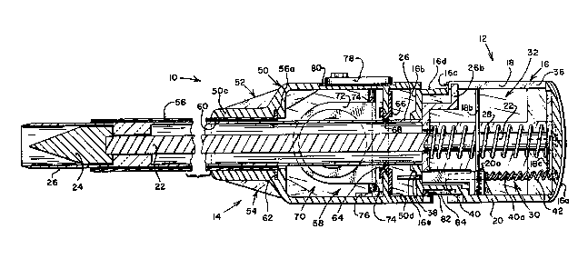
The drawings illustrate a trocar assembly, generally
designated 10, that is basically composed of two parts: a
trocar subassembly 12 and a trocar tube suba~sembly 14~
The two subas~emblies are interfitting, but designed to be
separable from each other. The basic elements of trocar
subassembly 12 are a hollow housing forming a grip or head
16 composed of nesting halves 18 and 20; an obturator 22
having a piercing tip 24; a generally tubular obturator
~leeve or shield 26; a ~pring 28 for biasing the shield;
and a latching mechanism shown generally at 30.
~` - ~4~ ~ 3 2 6g 2
Head 16 has a rounded rear wall 16a that fits
comfortably into the palm of the hand and a generally
rectangular front wall 16b. Wall 16b has a shoulder 16c
that defines a forward raised section shown generally at
16d. The two halves 18 and 20 are generally symmetrical
and snap fit together with four posts 18a extending
transversely from the inner wall of half 18. The head has
a central axial chamber 32 for receiving the obturator and
shield. Chamber 32 terminates in a generally triangular-
shaped recess 34 (as viewed in Fig. 3) having a narrowneck 34a formed in the inner face of the rear wall into
which a matingly formed rear end 22a of the obturator
shaft fits to hold the obturator in head 16.
The front wall 16b has a circular opening 32a that is
defined by a collar 16e and which opens into chamber 32.
As shown in Figs. 2-6, spring 28 encircles the rear end of
the obturator shaft with its ends seated against the inner
face of the rear wall of the grip and the rear end wall of
the shield. The side face of head half 18 has an axially
elongate opening 36. Formed as part of the rear end of
shield 26 is a protrusion or lip 26a which extends radi-
ally from the shield in line with the ~oint between head
halves 18 and 20. Extending upwardly and rearwardly from
the rear end of the shield is a position-indicating finger
26b which extends into opening 36 for indicating the posi-
tion of the shield relative to the obturator.
Disposed in head half 20, generally opposite from the
po~ition of lip 26a i~ a bore 38. Extending through this
bore for sliding movement relative to head 16 along an
axi9 parallel with the longitudinal axis'of the shield and
obturator i8 a trigger 40. Trigger 40 extends through
raised section 16d with an exposed forward extending tip.
The end of the trigger in chamber 32 is biased toward bore
38 by a spring 42 which extends between the end of the
3S trigger and the rear wall of head 16 in head half 20. A
~~ ` 5 1326~2~
rod section 40a is formed in the end of the trigger and
extends toward the rear wall of chamber 32 and is sized to
be received in spring 42 for aiding in holding the spring
in aiignment against the end of the trigger. The trigger
is further maintained in alignment relative to the chamber
by a guide 20a positioned next to the ~qide of the trigger
and another guide 18b extending from the face of head half
18 adjacent opening 36 to the corresponding surface of the
trigger. The end of spring 42 disposed against the rear
inner wall of head half 20 is held in position by a
partial channel 20b in which it is seated and an arm 18c
extending from head half 18 and seating against the spring
~nd seated against the inner wall.
The side of the trigger adjacent to guide 20a has
three generally planar sections. A guide section 40b is
disposed parallel with and adjacent guide 20a. An inter-
mediate section 40c is slightly recessed from section 40b,
except for a ridge 40d disposed at the end of section 40c
adjacent to the exposed tip of the trigger. Finally, a
further recessed end section 40e is also ad~acent to the
forward side of ridge 40d.
Opposite from trigqer 40 in the portion of chamber 32
defined by head half 20 is a leaf spring member 44. As
viewed in Figs. 3-6, Member 44 has a general narrow V-
shape with the base 44a of the IIVI' seated in a correspond-
ingly V-shaped cavity 46 in head half 20. One leg of the
spring member is pressed against the side of chamber 32.
The end 44b of the other leg is free standing and disposed
ad~acent collar 16e where it seat-~ in a block position
against lip 26a of the shield when the trigger i8
positioned in what is referred to as a lock position with
the exposed trigger tip extended. The leaf spring member
thus is also referred to as a second biasing means for
biasing end 44b in the block position. End 44b is accord-
ingly also referred to as a stop or means for preventing
- ~ -6- 1326~2~
the shield from moving to the extended position. Leaf
spring member 44 has a bend 44c in it intermediate the V-
base and end 44b. This bend puts the intermediate portion
of the leaf spring member closer to trigger 40. A portion
or arm 44d, also referred to as link means, of member 44
extends toward trigger 40. The distal end or tip 44e of
arm 44d has a slight curve, with the curved portion seated
on trigger side portion 40c and against ridge 40d with the
trigger in the lock position and the shield in the
extended position as shown in Fig. 3.
The basic elements of trocar tube subassembly 14 are:
a main body SO composed of two generally symmetrical
halves 52 and 54 that are held together by appropriate
fastening means; an axially elongate trocar tube S6; and a
flap valve mechanism 58. The rear end of body SO has a
rectangular recess SOa that mates with raised section 16d
on the front end of the grip of the trocar subassembly
when the two subassemblies are interfitted.
A front wall SOb of the body is curved to facilitate
gripping the trocar with the fingers and has a circular
opening 60 defined by a collar 50c in which the trocar
tube is mounted. The rear end of opening 60 expands into
a circumferential groove 62 into which a collar 56a on the
rear end of the trocar tube is seated to fix the tube
within collar 50c.
A rear wall 50d of the body haq a central circular
opening 64 in which a rubber grommet 66 is seated. Grom-
met 66 has a central opening 68 coextensive with opening
64. The obturator and shield are sized to pass through
the central grommet opening with the grommet orming a
seal around the shield.
~ ody 50 has an inner cavity 70 into which openings 60
and 64 open and in which flap valve mechanism 58 is
mounted. The flap valve mechanism includes a U-shaped
flapper 72, a shaft 74 which traverses the cavity and on
~7~ 13~2~
which the flapper is carried, a spring 76 disposed about
one end of the shaft, and an actuating lever/indicator 78
carried on one end of the shaft exteriorly of the body.
The exterior of the body at the location of the indicator
5 has a fan shaped recess 80 in which the indicator moves.
When the obturator and ~leeve are inserted in opening
68, the flapper valve opens, allowing the obturator and
sleeve to be fully inserted in trocar tube 56. The
indicator thus swings from a position indicating that
opening 68 is sealed to a position indicating it is open.
A lower lip lining an edge of the recessed rear wall 50d
has a nipple 82 extending inwardly~ The lower,outwardly
facing edge ad~acent raised portion 16d corresponding in
position to the nipple has a slot 84 in which the nipple
travels during normal use of the trocar assembly with the
two subassemblies joined. When the obturator subassembly
is removed from the trocar tube assembly, the nipple is
removed from the slot to allow separation.
The trocar assembly operates and is used as follows.
Prior to use, the trocar assembly will typically be in the
assembled form shown in Figs. 1-3 with the raised
rectangular section 16d fitting into recess 50a, and with
the obturator and shield inserted through the opening in
grommet 66, cavity 70, and the lumen of trocar tube 56.
The trocar shield is normally locked in its extended
position as shown in Figs. 1-3 for safety purposes and for
storage. In this position the piercing tip is shielded
and cannot be damaged by inadvertent contact with other
surfaces. In this locked position spring 28 biases shield
26 forwardly with lip 26a limiting the forward travel by
contact aqainst the inner surface of front wall 16b. The
bias of leaf spring member 44 keeps end 44b seated against
lip 26a, preventing rearward movement of the shield.
In order to unlock the shield, head 16 i~ pressed
toward main body 50 to the po~ition shown in Fig. 4. By
........... :
-8- 1 32~2~
doing so, raised section 16d, with the exposed tip of
trigger 40 protruding, is inserted into recess portion
SOa. Rear wall 50d is forced against the tip of the trig-
ger, causing the trigger to retract into chamber 32 to
what is referred to as a release position. This movement
usually takes place when the shield and obturator tip are
placed against an incision in the skin and pressure is
exerted against the skin by pressing against head 16.
Pressure on the head of the trocar assembly concurrently
shifts the trigger to the release position while applying
force against the skin tissue. The tip enters the inci-
sion and underlying tissue with continued pressure.
As the trigger moves to the release position, end 44e
of leaf spring member arm 44d is carried with it since
ridge 40d prevents the end from sliding along the trigger
side. This puts arm 44d in a more perpendicular alignment
across chamber 32, forcing free end 44b laterally away
from the shield, and therefore away from lip 26a, as shown
in Fig. 4. With leaf spring member end 44b displaced from
lip 26a, shield 26 is free to move rearwardly, exposing
obturator tip 24. The force of the body cavity wall tis-
sue on the shield forces it into the retracted position
shown in Fig. 5.
As the shield moves rearwardly, lip 26a contacts the
side of leaf spring member 44 between free end 44b and
bend 44c. Because of the angle of the leaf spring, it
acts like a cam with lip 26a to further displace free end
44b away from shield 26 to what is referred to as a
withdrawn position. Concurrently with this, the end 44e
of arm 44d is also displaced from side section 40c and
ridge 40d. The arm i9 biased toward the exposed tip of
the ~rigger 80 that as its end clears the ridge, it snaps
into a position ad~acent side section 40e. This is the
configurat~on ~hown in Fig. 5. The devices providing this
cam action are therefore also referred to collectively as
2 4
g
means for reactivating the blocking function of leaf
spring free end 44b.
Once the tip has penetrated the tissue and has
entered the cavity, the foxce against the front end of the
S shield ceases and the shield is automatically moved
axially back to its extended position through the action
of spring 28. Even with the two subassemblies pre~sed
together and trigger 40 in its release position, free end
44b of the leaf spring member seats against lip 26a when
the shield returns to the extended position. This
configuration is shown in Fig. 6. ~hus, while the
obturator tip remains in the body cavity, its tip is
protected by the protective shield which is locked into
the protective position so that the tip will not ac-
cidentally cut viscera and other internal tissue un-
intentionally.
The trocar subassembly may be withdrawn from the
trocar tube subassembly once the cavity has been
penetrated. In this operation, pressure is released from
head 16. Spring 42 is strong enough to push the sub-
assemblies apart, thereby returning the trigqer to the
lock position shown in Fig. 3 with the leaf spring member
arm end 44e back in place against trigger side section
40c. The obturator and shield are slid out of trocar tube
56 and main body 50. Spring 76 then forces flapper 72
against grommet 66, sealing opening 68. Air pressure
within the body cavity is thus maintained. In this
regard, body half 52 of body 50 is equipped with a
stopcock port 82 into which the nozzle of a ~topcock (not
30 shown) i8 in~erted. The stopcock will n~rmally be closed
during the trocar insertion to maintain the gas pres~ure
within the body cavity. If necessary, the stopcock may be
used as a conduit for passing additional insufflating gas
into the cavity.
` ~32~42~
--10--
After the obturator subassembly has been separated
from the trocar tube subassembly, surgical in~truments may
be inserted into the body cavity via the trocar tube sub-
assembly to view internal tissue~, perform operations
thereon, or drain body fluids. Indicator 78 may be used
as a handle to manually open valve flapper 76 to
facilitate such activities and also permit the removal of
specimens and to deflate the cavity.
While a preferred embodiment has been used to il-
lustrate the present invention, it will be understood that
variations in form and detail may be made without varying
from the scope and spirit of the invention as defined in
the claims. For example, the function of the trigger,
spring leaf member, and shield protrusion could be ef-
fected by appropriate sequencing of overlapping camsurfaces. Other equivalent modifications will also be
apparent to one skilled in the art of mechanical engineer-
ing, surgical instrument design, or related fields.