Note: Descriptions are shown in the official language in which they were submitted.
1 326828
This invention relates to devices for changing the
compre~sion ratio of internal combustion engines, by varying
the volume of a combustion chamber assumed when the piston i8
in the top dead center (TDC) position.
s
A compre~ion ratio-changing dovice for an internal
co~bustion engine i8 known, e.g. by Japanese Provisional
Patent Publlcation (Xokai) No. 58-91340, which comprises an
eccentric bearing interposed between the piston and the
conne¢ting rod ~uch that the axial position of the piston
relatlve to the connecting rod can be changed with a change
in the angular position of the eccentric bearing. The device
further comprises a hydraulically-operated lock pin arranged
within the connecting rod for being pushed into and moved
from tha eccentric bearing by means of hydraulic oil pressure
appliod thereto 80 a~ to cause the eccentric bearing to be
locked to and unlocked from the connecting rod, thereby
changing the compression ratio of the engine.
However, according the prior art device, hydraulic oil
pressure applied to the lock pin is supplied from two
independent main oil passages, one for ~etting a higher
compression ratio and the other for setting a lower
compression ratio, formed in the cylinder block by way o~
respective oil passages
3~
-- 1 --
X~ :
. : ,: ~ ,
1 326828
extending through the crankshaft, crank pin, and
connecting rod. These last-mentioned oil passages for
feeding hydraulic oil also serving as lubricating oil
require spacing for formation thereof within bearings
provided in the crankshaft, crank pin, etc. Since the
bearings are each disposed within a limited space, it
is difficult to obtain the spacing within the bearings
for formation of the dual-purpose oil passages for
changing the compression ratio and lubricating the
bearings. Furthermore, the aforementioned two main
oil passages are selected by means of a changeover
valve arranged within the cylinder block at a location
upstream of the main oil passages, in other words,
commands for bringing the lock pin into and out of its
locking position are issued at a location considerably
remote from the lock pin and transmitted to the lock
pin through the long oil passageways. As a
consequence, the lock pin does not move in quick
response to the commands, resulting in low
responsiveness in changing the compression ratio.
Another compression ratio-changing device has
been proposed, e.g. by Japanese Provisional Patent
Publication ~Kokai) No. 54-106724, which has a
hydraulic pressure chamber defined between an upper
inner end face of the piston and an opposed outer end
face of the piston guide which is secured to the
connecting rod and axially slidably received within
the piston. ~he piston is axially displaced relative
to the piston guide by applying thereto hydraulic
pressure within the hydraulic pressure chamber which
is supplied from a hydraulic pressure control device
provided on the cylinder block side, thereby changing
the volume of the combustion chamber and hence the
1 326828
compres~ion ratio of the engine.
However, according to the proposed device, the
hydraulic pressure for controlling the compression
ratiO is supplied from the hydraulic pressure control
device to the hydraulic pressure chamber by way of oil
passages formed through the crankshaft, crank pin and
connecting rod as well, thereby unavoidably requiring
spacing within bearings of the crankshaft and the
~rank pin for providing the oil passages for the
purpose of control of the compression ratio. In order
to not only obtain spacing for the oil passages for
controlling the compression ratio, but also secure
lubrication of the bearings, there may be supposed two
methods. That is, the first method is to provide an
exclusive oil passageway for controlling the
~ compression ratio in addition to the lubricating oil
passageway, while the second method i~ to provide a
dual-purpose oil passageway for feeding hydraulic oil
for controlling the compression ratio as well as
lubricating the bearings, the pressure of hydraulic
oil being set to values within such a range that the
hydraulic pressure can always serve to lubricate the
bearings, irrespective of whether it is set to a
higher value for higher compression ratio or to a
lower value for lower compression ratio. However,
according to the former method, it is difficult to
form the exclusive oil passageway within limited
spaces in the bearings. According to the latter
method, on the other hand, the lower hydraulic
pressure value for obtaining the lower compression
ratio cannot be set to a value low enough to
appropriately control the compression ratio because
such a low pressure value is too low for lubrication,
.~ - . . .
1 326828
and if the lower pressure value $8 set to a value higher than
such a low value, the higher hydraulic pressure value will
correspondingly be exces~ively hlgh, thereby necessitating
incrQasing the capacity of the hyraulic pressure control
device or the ma~s or weight of the piston Further, in this
prior art device, the hydraulic pres~ure 6upplied to the
hydraulic pressure cha ber i8 controlled by the hydraulic
pre~ur control device located remotely from the hydraulic
pre-~ur chambor, thu~ resulting in difficulty to obtain
guick displacement of the piston relative to the piston pin
and hence low responsiveness in changing the compros~ion
ratio of the engine
The invention provides a compression ratio-changing
lS device for use in an lnternal co~bustion engine, which i8
capabl- of changlng the compression ratio with i~proved
~esponsiveness as well as securing su~ficient bearlng and
lubricating functions oS the crankshaft, etc, while it is
~impl- in structure, roguiring no substantial modification of
the crankshaft, et¢
According to the present invention, there is provided a
compression ratio-changing device for an internal coi~ustion
engino including a cylinder block, at least one cylinder
having a cylinder wall formed in the cylinder block, a
crankshaft, at least one piston received within the at least
one cylinder for reciprocating therein, and at least one
connecting rod connecting the at least one piston to the
crankshaft, wherein a combustion chamber iB defined by the
cylinder and the piston, a change in the volume of the
- 4 -
::
: ~r i
.~ ~
- . . . - , .
1 326828
eombu~tion ehamber causing a change in the eompression ratio
of the engine, the device comprising:
a hydraulic oil source;
oil passage means formed through the connecting rod and
S connected to the hydraulic oil source:
coubustion chaiber volume-changing ~ean~ provided in the
pi~ton and operable by ~eans of hyraulie pressure supplied
fro~ th hydraulie oil ~oure through the oil passage ~eans
for ehanging the ~olu~e o~ the eo bu~tion eha ber;
hydraulic pressure control valve neans arranged in the
eonneeting rod for eontrolling the supply of the hydraulic
pres~uro to the co~bustion ehamber voluue-ehanging ~eans; and
driving ~ean~ provided at the eyllnder wall for driving
the hydraulie pres~ure ¢ontrol valve ~eans ~or eausing the
lS eonbu~tlon cha~b r volu~e-changing ~eans to change the volume
of the eo bustion chamber.
The above and other ob~ects, features and advantages of
the invention will be ~ore apparent from the ensuing detailed
d~eription taken in eon~unetion with the aeeompanying
drawings.
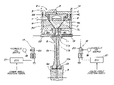
Fig. 1 i~ a ViQW showing a general arrange~ent of a
eo~pression ratio-changing device for an internal combustion
engine according to a first embodi~ent of the invention;
Fig. 2 is an enlarged view of an essential part of the
device of Fig. l;
Fig. 3 is a cross-sectional view taken along line III-
III in Fig. 2;
Fig. 4 is a view showing a general arrangement of a
_ 5 _
:~ .
Xl
. ~ ; . -. .. . .. . . .. . .
. ! "
1 326828
compression ratio-changinq device according to a second
embodiment of the invention; and
Fig. 5 is a view similar to Fig. 2, showing a third
e~bodiment of the invention.
s
The invention will now be described in detail with
reference to the drawinqs ~howing embodiments thereof.
CorrQsponding or ~imilar elements or parts are designated by
identical reference numerals throughout all the figures, and
detailod description thereoP is omitted in the description of
embodiments other than a first embodiment.
Fig. 1 through Fig. 3 show a compression ratio-changing
device for use in an internal combustion engine according to
lS the first embodiment of the invention. Referring to Fig. 1,
r ferenc- nu~eral 1 represent6 a cylinder block of the
engine, in which cylinder~ la are formed, only one of which
is shown. A piston 2 i8 slidably received withln the
Qlinder la for reciprocating motion therein. The piston 2
comprise~ a movable piston head 3, right and left halves
thereof being illustrated in different positions for better
understanding, and a piston base 4. The movable piston head
3 is fitted on the piston base 4 such that the former is
axially displaceable by a predetermined amount h relative to
the latter. A higher compression ratio hydraulic chamber 5
and a lower compression ratio hydraulic chamber 6 can be
Xj
, . . .
. ~ :
.
1 326828
-- 7
defined between the members 3 and 4, as described
later. A piston pin 7 has an intermediate portion
thereof force-fitted through a smaller end of a
connecting rod 8 and opposite end portions thereof
rotatably fitted in piston pin holes 4a radially
formed through the piston base 4. Higher compression
and lower compression ratio oil passages 8H, 8L are
axially formed through the smaller end of the
connecting rod 8, and are always aligned,
respectively, with higher compression and lower
compression ratio oil passages 7H, 7L formed through
the piston pin 7 in a manner extending obliquely
diametrically therethrough. On the other hand, formed
in the piston base 4 are a higher compression ratio
lS oil passage 4H and lower compression ratio oil passage
4L, which communicate the higher compression ratio oil
passage 7H and the lower compression ratio oil passage
7L of the piston pin 7 with the higher compression
pressure chamber 5 and the lower compression pressure
chamber 6, respectively, when the piston 2 is at the
....
bottom dead center and in the vicinity thereof.
Furthermore, an oil passage 8a is longitudinally
formed through a main portion of the connectin~ rod 8
for feeding hydraulic oil pressure from a lubricating
oil passage 9a formed in a crank pin 9 to the higher
compression ratio oil passage 8H or the lower
compression ratio oil passage 8L through a groove and
hole 10a formed through a bearing member 10 of the
crank pin 9. The lubrcating oil passage 9a is
connected to a lubrcating oil source 30 to be supplied
with pressurized oil pressure therefrom.
A spool valve 11 as a hydraulic pressure control
valve is arranged within the smaller end of the
1 326828
-- 8 --
connectinq rod 8. The spool valve 11 comprises a
spool valve bore llb diametrically formed through the
smaller end of the connecting rod 8 in a manner
extending parallel with the piston pin 7, and a spool
lla slidably received within the spool valve bore llb.
The spool valve bore llb has opposite end portions
tapered so as to effectively receive pressurized oil
jetted from oil jet pipes 19, 22 opposed thereto,
hereinafter described. The higher compression and
lower compression ratio oil passages 8H, 8L each have
one end on the crank pin side opening into the spool
valve bore llb, while the oil passage 8a has its one
end on the piston pin 7 side opening into the spool
valve bore llb.
lS The spool lla has an outer periperal surface
thereof formed with an annular groove 12 having a
predetermined width at an axially central portion
thereof, as clearly shown in Fig. 2.
With such arrangement, the spool lla axially
slides within the spool valve bore llb so that it can
assume two positions, that is, a higher compression
ratio position where the oil passage 8a is in
communication with the higher compression ratio oil
passage 8H via the annular groove 12, as shown in Fig.
1, and a lower compression ratio position where the
passage 8a is in communication with the lower
compression ratio oil passage 8L via the annular
groove 12, i.e., a position of the spool lla rightward
of the position shown in Fig. 1.
A click stop device 13 is provided between the
connecting rod 8 and the spool lla to retain the spool
lla in the higher compression or lower compression
ratio position, thereby preventing the spool lla from
. ~ , ~ .
.; : . . :-.-.
1 326~28
g
falling out of the valve bore llb while sliding in the
valve bore llb. The click stop device 13 comprises a
spring-receiving bore 8b formed in the connecting rod
8 and opening into the spool valve bore llb, a coiled
spring 14 received within the spring-receiving bore
8b, annular recesses 12H and 12L formed in axially
opposite lateral side portions of the annular groove
12, and a steel ball 15 arranged in the annular groove
12 at the open end of the spring-receiving bore 8b for
selective engagement by the force of the spring 14
with the annular recess 12H or 12L. Specifically,
when the spool lla is moved into the higher
compression ratio position, the steel ball 15 is
brought into engagement with the annular recess 12H,
as shown in Figs. 2 and 3, and on the other hand, when
the spool is moved into the lower compression ratio
position, the ball 15 is brought into engagement with
the annular recess 12L.
Driving devices 16, 17 are provided in the
cylinder block of the engine for forcibly displacing
the spool lla into the higher compression ratio and
lower compression ratio positions, respectively. The
driving devices 16, 17 each comprise a lubricating oil
source 18, 18 for supplying lubricating oil to the
engine, a higher compression or lower compression
ratio oil jet pipe 19, 22 through which oil is jetted
against the spool lla, and a higher compression or
lower compression ratio solenoid valve 20, 23 for
regulating the supply of pressurized oil through the
oil jet pipe 19, 22. The solenoid valves 20, 23 are
controlled by an electronic control unit (ECU) 21
which receives a crank angle position signal for
selectively energizing or deenergizing the solenoid
- . - ......................... . . :
~: ' , . ' ' ' , . '
1 326828
-- 10 --
valves 20, 23 over a predetermined time period or
within a predetermined crank angle range with a piston
bottom dead center (BDC) angle as the middle time or
angle. The oil jet pipes 19, 22 are so located as to
axially align with the spool lla when the piston 2
assumes the BDC position and its vicinity, as shown in
Fig. 1.
The operation of the compression ratio-changing
device constructed as above will be described
hereinbelow.
When the engine is to be brought into higher
compression ratio operation as required by operating
conditions of the engine, the solenoid valve 20 for
higher compression ratio is energized and at the same
. ~
time the solenoid valve 23 for lower compression ratio
is deenergized by the electronic control unit 21 over
a predetermined time period or within a predetermined
crank angle range with the BDC angle as the middle
time or angle, the solenoid valve 20 is opened to
allow pressurized oil from the lubricating oil source
18 to pass therethrough into the oil jet pipe 19. The
oil is then jetted against the spool lla from the oil
jet pipe 19, which is then aligned with the spool lla,
thereby causing the spool lla to be displaced to the
higher compression ratio position, as shown in Fig. 1.
As a result, the oil passage 8a is brought into
communication with the higher compression ratio oil
passage 8H through the annular groove 12 of the spool
lla. On this occasion, the steel ball 15 is brought
into engagement with the annular recess 12H of the
annular groove 12 by the force of the spring 14 and
holds the spool lla in the higher compression ratio
position. Consequently, hydraulic pressure is
,
1 32682~
supplied from the lubricating oil passage 9a of the
crank pin 9 through the groove and hole 10a of the
bearing member 10, the oil passage 8a, the annular
groove 12 of the spool llb, and the higher compression
ratio oil passages 8H, 7H, 4H into the hydraulic
pressure chamber 5 for higher compression ratio,
thereby causing the movable piston head 3 to be
upwardly displaced relative to the piston base 4, as
shown at the left half of the piston head 4 in Fig. 1.
Thus, the combustion chamber la is decreased in volume
and hence the engine is brought into higher
compression ratio operation.
On the other hand, when the engine is to be
brought into lower compression ratio operation as
required by operating conditions of the engine, the
solenoid valve 23 for lower compression ratio is
energized and at the same time the solenoid valve 20
for higher compres~ion ratio is deenergized by the
electronic control unit 21 over the predetermined time
period or within the predetermined crank angle range
with the BDC angle as the middle time or angle, so
that pressurized oil is jetted against the spool lla
through the oil jet pipe 22 which is then in alignment
with the spool lla, thereby causing the spool lla to
be shifted from the higher compression ratio position
into the lower compression ratio position. As a
result, the oil passage 8a is brought into
communication with the lower compression ratio oil
passage 8L through the annular groove 12 of the spool
lla, and the steel ball 15 is brought into engagement
with the annular recess 12L of the annular groove 12
by the force of the spring 14 and holds the spool lla
in the lower compression ratio position.
'
r
1 326828
Consequently, hydraulic pressure is supplied from the
lubricating oil passage 9a of the crank pin 9 through
the groove and hole lOa of the bearing member lO, the
oil passage 8a, the annular groove 12 of the spool
lla, and the lower compression ratio oil passages 8L,
7L, 4L into the hydraulic pressure chamber 6 for lower
compression ratio, thereby causing the movable piston
head 3 to be downwardly displaced relative to the
piston base 4, as shown at the right half of the
piston head 4 in Fig. 1. Thus, the combustion chamber
la is increased in volume and hence the engine is
brought into lower compression ratio operation.
In the above embodiment, the spool valve ll as
the hydraulic pressure control valve is located in the
vicinity of the higher compression and lower
compression ratio hydraulic pressure chambers S and 6
so that the total length of the oil passages between
the former and the latter is reduced, thereby
improving the responsiveness in changing the
compression ratio of the engine.
Further, pressurized oil is jetted from the oil
jet pipe 19, 22 against the spool lla only after the
piston 2 reaches a position near the BDC and
accordingly the spool llb is brought into alignment
with the oil jet pipe l9, 22, which results in
reduction in the amount of oil consumed and also
. . .--. .
enables setting a long oil jetting time period.
In the above embodiment, combustion chamber
volume-changing means is constituted by the movable
piston head 3, piston base 4, higher compression ratio
hydraulic pressure chamber 5, lower compression ratio
hydraulic pressure chamber 6, higher compression ratio
oil passages 4H, 7H, 8H and lower compression ratio
~, .
- .
~. . . -
- .. ~........ . .
1 326828
- 13 -
oil passages 4L, 7L, 8L.
Next, a second embodiment of the present
invention will be described with reference to Fig. 4.
The second embodiment is distinguished from the
first embodiment in that driving means 24 is employed
for displacing the spool lla by means of an
electromagnetic force in place of the driving means
16, 17 of the first embodiment utilizing oil jet. The
driving means 24 comprises an electric power supply
25, a pair of switches 26 operated by an electronic
control unit (ECU) 21, and a pair of electromagnets
27, 27.
A spool valve 11' comprises a spool lla' formed
by a permanent magnet with magnetic poles S, N at
opposite ends thereof. The electromagnets 27, 27 are
disposed in opposed relation to opposite end faces of
the spool lla'.
With the above arrangement of the compression
ratio-changing device, when the switches 26 are
changed over to a higher compression ratio position by
the electronic control unit 21, as shown by the solid
lines in Fig. 4, the electromagnets 27, 27 both assume
a polarity of S so that the spool lla' leftwardly
moves and assumes a position for effecting higher
compression ratio operation of the engine, as shown in 25 Fig. 4. On the other hand, when the switches 26 are
changed over to a lower compression position by the
electronic control unit 21, as shown by the broken
lines in Fig. 4, the electromagnets 27, 27 both assume
a polarity of N so that the spool lla' rightwardly
moves from the higher compression ratio position of
Fig. 4 into the lower compression ratio position for
effecting lower compression ratio operation of the
engine.
- ; . ~
1 326828
- 14 -
The other elements and parts other than those
referred to above are substantially identical in
construction and function with corresponding ones of
the first embodiment, description of which is
therefore omitted.
A third embodiment will now be described with
reference to Fig. 5.
The third embodiment is distinguished from the
first embodiment in that the hydraulic pressure
chamber 6 for lower compression ratio, the lower
compression oil passage 4L, and the lower compression
ratio oil passages 8L, 7L, as employed in the first
embodiment, are omitted, which constitute part of the
combustion chamber volume-changing means. The spool
lla has an oil-leaking groove llL axially formed in an
outer peripheral surface thereof, one end of which is
registrable with a higher compression ratio oil
passage 8H during lower compression ratio operation of
the engine and the other end opens in an end face of
the spool lla. The other elements and parts not
reerred to above are substantially identical in
construction and function, description and
illu~tration of which are therefore omitted.
According to the third embodiment, the
compression ratio-changing device operates in the same
manner as in the first embodiment described
hereinbefore, when the engine is to be brought into
higher compression ratio operation. When the engine
is to be brought into lower compression ratio
operation, the spool lla is rightwardly shifted from
the higher compression ratio position in Fig. 5 into
the lower compression ratio position by the force of
pressurized oil jetted thereagainst in the same manner
~:
~ , .
, , ,: ' ', ~ ~
,
1 326~28
- 15 -
as in the first embodiment. Then, the oil-leaking
groove llL in the spool lla becomes registered and
communicated with the higher compression ratio oil
passage 8H so that the hiqh pressure oil leaks from
the higher compression ratio oil passage 8H through
the oil-leaking groove llL and falls to the crank pin
9 side. Consequently, no hydraulic pressure is
supplied to the hydraulic pressure chamber for higher
compression ratio to cause the movable piston head to
downwardly move relative to the piston base 4. Thus,
the volume of the combustion chamber la is increased
and hence the engine is brought into lower compression
ratio operation.
In the embodiments described above, other types
of valve~ such as a rotary valve or a valve with a
plate cam may be used as the hydraulic pressure
control valve in place of the spool valve 11, ll'.
Furthermore, the combustion chamber
volume-changing means is not limited to those employed
in the above described embodiments, but it may
alternatively be constituted by an eccentric bearing
or an eccentric piston pin having offset axis which
are arranged such that the eccentric bearing or the
piston pin is locked to and unlocked from the
connecting rod or the piston by means of a
hydraulically-operated lock pin for changing the
compression ratio of the engine, as disclosed by
Japanese Provisional Patent Publication (Kokai) No.
58-91340.