Language selection

Search

Patent 1326962 Summary

Third-party information liability

Some of the information on this Web page has been provided by external sources. The Government of Canada is not responsible for the accuracy, reliability or currency of the information supplied by external sources. Users wishing to rely upon this information should consult directly with the source of the information. Content provided by external sources is not subject to official languages, privacy and accessibility requirements.

Claims and Abstract availability

Any discrepancies in the text and image of the Claims and Abstract are due to differing posting times. Text of the Claims and Abstract are posted:

  • At the time the application is open to public inspection;
  • At the time of issue of the patent (grant).
(12) Patent: (11) CA 1326962
(21) Application Number: 1326962
(54) English Title: DRIVESHAFT WITH DRIVING ELEMENTS ATTACHED TO IT IN GROUPS
(54) French Title: ARBRE DE COMMANDE AUQUEL SONT FIXES DES ORGANES D'ENTRAINEMENT GROUPES
Status: Expired and beyond the Period of Reversal
Bibliographic Data
(51) International Patent Classification (IPC):
  • F16D 01/06 (2006.01)
  • F01L 01/047 (2006.01)
  • F16H 53/02 (2006.01)
(72) Inventors :
  • SWARS, HELMUT (Germany)
(73) Owners :
  • EMITEC GESELLSCHAFT FUR EMISSIONSTECHNOLOGIE MBH
(71) Applicants :
  • EMITEC GESELLSCHAFT FUR EMISSIONSTECHNOLOGIE MBH (Germany)
(74) Agent: SMART & BIGGAR LP
(74) Associate agent:
(45) Issued: 1994-02-15
(22) Filed Date: 1988-10-03
Availability of licence: N/A
Dedicated to the Public: N/A
(25) Language of filing: English

Patent Cooperation Treaty (PCT): No

(30) Application Priority Data:
Application No. Country/Territory Date
G 87 13 285.0 (Germany) 1987-10-02

Abstracts

English Abstract


ABSTRACT
The force-locking connection between a shaft and
driving elements attached to it is improved or achieved
via a slight plastic expansion of the shaft in that the
driving elements are arranged in groups and connected by
connecting sleeves produced so as to be integral with the
driving elements. The higher degree of elastic expansion
is limited to the region of the connecting sleeves so that
the driving elements themselves are largely excluded from
this process. The dimensional accuracy of the finish-
machined driving elements is not adversely affected. If
necessary, recesses may be produced to form webs as a
result of which the elastic deformation occurring in the
inner region is reduced.


Claims

Note: Claims are shown in the official language in which they were submitted.

- 6 -
THE EMBODIMENTS OF THE INVENTION IN WHICH AN EXCLUSIVE
PROPERTY OR PRIVILEGE IS CLAIMED ARE DEFINED AS FOLLOWS:
1. A driveshaft with driving elements attached to it,
characterized in that at least some of the driving elements
are arranged in groups and that the individual members of
the group are connected to each other by elastically
expanded, thin-walled sleeves.
2. A driveshaft according to claim 1, characterized in
that the driving elements are produced so as to be integral
with the connecting sleeves.
3. A driveshaft according to claim 1, characterized in
that the driveshaft is hollow and that at least in the
region of the connecting sleeves it is plastically
expanded.
4. A driveshaft according to claim 1, characterized in
that the driving elements and/or the connecting sleeves are
shrunk on to the shaft.
5. A driveshaft according to claim 1, 2, 3 or 4,
especially having non-rotation-symmetrical driving
elements, characterized in that the driving elements have
been provided with axial recesses in such a way that
between a radially inner region of the elements extending
concentrically relative to the shaft and a radially outer
region of essentially uniform thickness, webs with a
reduced cross-section are formed.
6. A driveshaft according to claim 1, 2, 3 or 4,
characterized in that prior to being attached to the shaft,
the driving elements have a larger inner diameter than the
connecting sleeves.

- 7 -
7. A driveshaft according to claim 1 or 2,
characterized in that at least some of the driving
elements are produced of a material having an expanding
ability of at least 0.5%.

Description

Note: Descriptions are shown in the official language in which they were submitted.


1326962
The invention relates to a driveshaft with driving
elements attached to it. The driving elements referred to
are meant to be those elements which are suitable for co-
operating with other machinery parts such as gears, cams,
but also parts of friction and roller bearings. Below,
the invention will be described in connection with a
camshaft intended to be incorporated in an internal
combustion engine, but it is not limited to this
application. In its EP-A-0 213 529, one of the applicants
has proposed a process for attaching driving elements to a
hollow shaft in the case of which the latter consists of
commercial tube material, with the elements being slid on
and subsequently fixed to it by expanding the tube
portions underneath. The material of the tube itself is
plastically deformed whereas that of the cam is only
elastically deformed, with the spring-back of the latter
causing the pressure resulting in the force-locking
connection between the two parts. To enable the
connection to withstand the loads occurring in operation,
the product of the pressure force and the pressurized face
must achieve a certain value. If, as has been the case so
far, the width of the cam as well as the outer diameter of
the hollow shaft are not increased beyond the dimensions
applied for other design reasons, a relatively high
expansion pressure (in the region of 2500 bars) is
required for the shaft to undergo the necessary plastic
deformation and the cam the necessary elastic deformation.
This deformation is not limited to an inner region
~ :, . ., ". ., "
; ,,. .. ,, . , ~ .. :..... ... .-. : :.: .

1326962
- 2 -
ad~oining the ~haft, but extends across the entire cross-
section of the cam, and because the cam is not rotation-
symmetrical, the extent of the deformation is azimuthally
variable. It has been found that in consequence, one of
the advantages aimed at with the above-mentioned process
has been lost, i.e. to dimensionally finish-machine the
cam prior to assembly and, possibly, specifically
influence the material structure (for instance by surface
hardening). Since expansion of cams hardened in such a
way may cause surface cracks, the applicants, in their
German application P 37 17 534.3 which does not form part
of the prior art, proposed to divide the driving elements
into axially separate regions whose materials have
different properties and especially different expanding
coefficients.
It i6 the object of the present invention to provide
a driveshaft having driving elements attached to it in a
~ force-locking way in the case of which the degree of
elastic expansion is so slight that it does not extend as
far as their boundary regions, thereby not putting the
dimensional accuracy of the finish-machined driving
elements at risk. Furthermore, the object is to reduce
the necessary expansion pressure to approximately half the
value given above, a measure which increases the service
life of the seals which, on the probe used for expanding
purposes, limits the regions to be expanded below the
driving elements.
The objective is achieved by a driveshaft with
driving elements attached to it, characterized in that at
3~ least some of the driving elements are arranged in groups
and that the individual members of the group are connected
to each other by elastically expanded, thin-walled
sleeves. If, as proposed, the driving elements are at
least partially connected to each other by thin-walled
sleeves (which in consequence have a greater expansion
. . . . -- - - -- - - . : ~ ,
. ~ .:: .; . .

1326962
ability), e.g. in the form of double cams such as have
recently been used for multi-valve internal combustion
engines, on the one hand, the area available for producing
the force-locking connection is increased, as a result of
which the degree of elastic deformation may be reduced,
and because the sleeves are more easily expandable due to
their walls being thinner, the expansion pressure itself
may be reduced. The elastic deformation in the driving
elements may be limited to a radially inner region. It is
also possible to combine driving elements of different
kinds into groups, such as cams and bearing bushes, or the
connecting sleeves themselves, by selecting a suitable
type of material and surface condition, may be used for
the latter purpose.
In a further embodiment of the invention, the
driving elements combined in a group and the associated
connecting sleeves have been produced in one single part;
axially different material properties are possible but not
necessary.
The driving elements may be fixed on the one hand
through internal expansion of the shaft which is hollow
for this purpose or, on the other hand, by the equivalent
process of shrinking on. As with the latter process, in
view of the stability of the material structure, the
driving elements cannot be heated to any temperature, the
area pressures achieved in the course of the subsequent
cooling process are relatively low, so that an increase in
the pressurized area is particularly significant.
Especially for driving elements which, like cams, do
not have a rotation-symmetrical cross-section, it is
proposed to assist the reduction in elastic deformation
between the inner face and the outer face of the element
by reducing the material thickness of the latter along a
certain region looking at its longitudinal section so that
..
. ~ ~ . . --. -.

1326962
- 4 -
the out~ide of the element iB no longer subject to any
resulting deformation.
It is further proposed to limit the force-locking
effect to the region between the 61eeves and the shaft,
but to increase slightly the inner diameter of the driving
elements so that the expansion of the ~haft only leads to
the gap between the two parts to be closed without
noticeably expanding the element.
The requirements in respect of the expanding ability
of the material of the driving elements may be kept
relatively low so that these may be produced from
malleable cast iron for example, a material which has
other advantageous properties which make it particularly
suitable for this application.
BRIEF DESCRI~TION QF~EHE DRAWINGS
In a drawing which illustrates by way of example
only preferred embodiments of the invention,
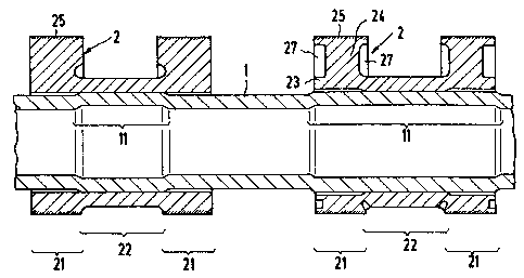
Figure 1 is a cross-section illustrating a
driveshaft embodying the invention.
Embodiments of the invention are illustrated in the
drawing in the form of axial longitudinal sections.
Double cams 2 have been slid on to the hollow shaft 1,
with each double cam 2 consisting of two portions 21
forming the actual cam and a sleeve 22 connecting them. A
hydraulic pressure probe which is not illustrated here but
which i8 known to the person skilled in the art, is used
to expand regions 11 of the hollow shaft which are
plastically deformed in the process. The deformation is
passed on to the connecting sleeves 22, but only within
the elastic range; their spring-back achieved the force-
locking connection connecting the shaft and the driving
elements. The expanded range 11 ls limited (lefthand half
.~. ... , . ~ . . . . . . . .. -- . .. ... .... ........... . . . .
, . .
. ~ .
- . . .. . .:: l .

13269~2
- 5 ~
of Figure 1) to that part of the hollow shaft 1 positioned
opposite the connecting sleeve 22 60 that the cam portions
21 are not or only slightly affected by elastic
deformation. The gap remaining between the hollow shaft 1
and the cams has been given exaggeratedly large dimensions
in the Figure. In a further embodiment (righthand half of
Figure 1), the expanded region 11 extends over the entire
double cam 2. In order to prevent the deformation of the -~
cam 21 from extending over an unacceptably long distance,
especially as far as its surface 25, either the cams 21
may have a slightly larger internal diameter than the
connecting sleeves 22 from the start so that in this case,
too, elastic deformation is practically passed on to the
latter only, or it is possible to provide recesses 27 as a
result of which webs 24 are formed between a radially
inner region 23 which is also elastically expanded and the
outer region 25, with the elastic deformation being
eliminated completely in the webs 24.
. ~ . . .. . . . . ..... . , . , . . ... " . . . ..

Representative Drawing
A single figure which represents the drawing illustrating the invention.
Administrative Status

2024-08-01:As part of the Next Generation Patents (NGP) transition, the Canadian Patents Database (CPD) now contains a more detailed Event History, which replicates the Event Log of our new back-office solution.

Please note that "Inactive:" events refers to events no longer in use in our new back-office solution.

For a clearer understanding of the status of the application/patent presented on this page, the site Disclaimer , as well as the definitions for Patent , Event History , Maintenance Fee  and Payment History  should be consulted.

Event History

Description Date
Time Limit for Reversal Expired 2010-02-15
Letter Sent 2009-02-16
Inactive: IPC from MCD 2006-03-11
Inactive: Late MF processed 2002-03-20
Letter Sent 2002-02-15
Grant by Issuance 1994-02-15

Abandonment History

There is no abandonment history.

Owners on Record

Note: Records showing the ownership history in alphabetical order.

Current Owners on Record
EMITEC GESELLSCHAFT FUR EMISSIONSTECHNOLOGIE MBH
Past Owners on Record
HELMUT SWARS
Past Owners that do not appear in the "Owners on Record" listing will appear in other documentation within the application.
Documents

To view selected files, please enter reCAPTCHA code :


To view images, click a link in the Document Description column. To download the documents, select one or more checkboxes in the first column and then click the "Download Selected in PDF format (Zip Archive)" or the "Download Selected as Single PDF" button.

List of published and non-published patent-specific documents on the CPD .

If you have any difficulty accessing content, you can call the Client Service Centre at 1-866-997-1936 or send them an e-mail at CIPO Client Service Centre.


Document
Description 
Date
(yyyy-mm-dd) 
Number of pages   Size of Image (KB) 
Claims 1994-07-20 2 47
Abstract 1994-07-20 1 24
Drawings 1994-07-20 1 17
Descriptions 1994-07-20 5 196
Representative drawing 2001-08-02 1 15
Maintenance Fee Notice 2002-03-17 1 179
Late Payment Acknowledgement 2002-03-26 1 172
Maintenance Fee Notice 2009-03-29 1 170
Fees 1997-01-19 1 61
Fees 1996-01-09 1 40
Courtesy - Office Letter 1989-02-02 1 35
Prosecution correspondence 1991-05-21 3 40
Examiner Requisition 1991-01-08 1 44
Prosecution correspondence 1993-11-16 1 30