Note: Descriptions are shown in the official language in which they were submitted.
~327278
Suspension device or the support
legs of a jack-up oil platform
The present invention relates to a suspension device
for the support legs of pla~forms for oil drilling or
S production at sea, and more particularly relates to
jack-up platforms.
The platforms of this type generally comprise legs
which bear on the sea bed and a hull which is mounted on
the leg to be movable and adjustable in height along
said legs.
The whole of the platforms is brought in a floating
condltion to the drilling or production site and the legs
are lowered until they contact the sea bed, then the
hull is raised above the level of the sea by bearing
; lS against the legs, up to an altitude which puts it ouf o
reach of the~highest waves.
The hull is therefore movable along the legs of the
platform by raising meahanisms connected to said hull
and including output gear pinions whose bearings are con-
; 20 nected to the hul} and which cooperate wlth racks mounted
on at least a part of the length of the legs. These gear
pinions are driven by a plurality of electric motors asso-
with speed reducers having a very high speed reducing ratio.
~: :
At the moment of contact of a leg with the bottom o
the sea, at the end of the descent, the impact may be very
132727~
violent in view of the movements of the hull under the
effect of the swell. These shocks are transmitted to the
raising mechanisms and this subjects the multiple gears of
the speed reducers to a very high stress.
In order to ensure a good behaviour of the gears of
the speed reducers at the moment of the contact of the legs
with the bottom of the sea, it is therefore neces~ary to
considerably overdimension them or to await favourable
weather conditions which increase the ¢osts of the instal-
lation.
An object of the invention is therefore to overcome
the aforementioned drawbacks o conventional devices by
providing a suspension device for jack-up oil plat-
form legs which, while being of a relatively simple cons-
truction, permits a decrease in the stresses due to theshocks in the structure, and above all in the gear pinions
; of the speed reducers, and to achieve the laying of the
platform with more severe conditions, ~ therefore in a wider
ra,n,ge of meteorological,, conditions, which decreases the costs
~0 of the installation.
The invention therefore provides a suspension device
;~ for support ~egs of a jack-up oil platform comprising
a hull mounted on the legs to be movable therealong by
driving mechanisms including a plurality of output gear
pinions cooperative with racks mounted on at least a part
of the length of the legs, each of said output pinions
being drivable by an electric motor associated
: - , , , . , .. ,, ." .. ,., .:: , ,
.:. : ~ . ~., ,. . ,~, :, . " , . . .
, , ~ ,, , -; . :
-
, ~ : ' , ~ ~: :
1 327278
with a speed reducer, pivotally mounted on a structure
which supports them and is connected to the hull by
means of at least one bearing allowing angular movement
of said speed reducer and each corresponding output
gear pinion, each speed reducer of the driving
mechanisms being cooperative with an energy absorption
mechanism comprising at least one torsionally
elastically yieldable support element connected to said
corresponding speed reducer and ensuring a progressive
absorption of the shock, in particular at the moment of
the laying of the legs on the sea bed.
According to a still broad aspect of the present
invention there i5 provided a suspension device used in
a jack-up oil platform having a hull, legs mounted to
the hull for supporting the hull on a sea floor, with
the legs and the hull movable relative to one another.
A suspension device is connected between the hull and
the legs for moving the legs and the hull relative to
one another. The device comprises a driving mechanism
includiny respective racks extending along at least a
portion of each of the legs. At least one output
pinion meshes with each of the racks. An electric
motor is operatively connected to each the output
pinion for rotating each output pinion. A respective
speed reducer is connected to and couples each electric
motor and a respective one of the output pinion. A
structural support is provided to support the driving
mechanism on the hull. The structural support includes
at least one bearing pivotally supporting each of the
speed reducers so as to allow the speed reducer to
pivot relative to the structural support when shock is
imparted thereto through the output pinion connected
thereto. Energy absorbing means is connected to each
of the speed reducers for absorbing shock imparted to
the driving mechanism through each the output pinions.
The energy absorbing means comprises respective support
means associated with each of the speed reducers and
~ r'`d
.
1327278
- 3a -
has an axis about which the support means is
torsionally elastically yieldable. Connscting means is
connected between each of the support means and the
speed reducer associated therewith for transmitting
pivotal movement of the speed reducer into torsion
about the axis of the support means. Each of the
support means is secured in the device so as to
elastically deflect about the axis thereof when the
pivotal movement is transmitted thereto by the
connecting means.
A better understanding of the invention will be
had from the following description which is given
solely by way of example with reference to the
accompanying drawings, in which:
Fig. 1 is a diagrammatic elevational view of a
jack-up oil platform in the configuration corresponding
to the lowering of the legs.
Fig. 2 is a diagrammatic view to an enlarged
scale of a section of one of the legs of the platform
showing a leg shifting mechanism.
Fig. 3 is a sectional view taken on line 3-3 of
Fig. 2.
Fig. 4 is an elevational view of a first
embodiment of the suspension device according to the
invention.
Fig. 5 is a sectional view taken on line 5-5 of
Fig. 4.
Fig. 6 is an elevational view of a variant of
the suspension device according to the invention.
Fig. 7 is an elevational view of another variant of
~B." -` .
, : . . , :
,: ' :' ' ' ~ :
`~327278
the suspension device according to the invention.
Fig. 8 i5 an elevational view o~ a still further va-
riant of the suspension device according to the invention.
Fig. 1 shows diagrammatically a jack-up or self-li~ting oil
platform ccmprising a hull 1 movably mounted on vertical
legs 2 adapted to rest on the sea bed 3 when the platform
is in the drilling or production position.
Each of the vertical legs 2 has, in the presently-
described embodiment, a triangular sectional shape and ~`
includes three pillars2a interconnected by a lattice struc-
ture of metal yirders. It terminates in its lower part
in a foot 4 which, in the presently-described embodiment,
has a hexagonal shape.
~ The platform is equipped, in the region of each leg 2,
;~ 15 with a system 10 for shifting and suspending the hull 1
- relative to said legs. This shifting system 10 permits
the lowering of the legs 2 down to a position in which they
are in contact with the sea bed, then, by bearing against
the legs, the raising of the hull 1 a~ove the sea up to
Zo an altitude which puts it out of reach of the highest waves.
For this purpose, as shown in Figs. 2 and 3, the
pillars 2a of the legs 2 are provided with diametrically
opposed racks 5 disposed on a part of the length of the
~. :
legs 2 and with which are cooperative output gear pinions
11 of motor drlve mechanisms 12 mounted on the hull 1. For
example, six output gear pinions may be provided for each
pillar 2a,each being equipped with a motor drive mechanism 12.
13272~8
-- 5
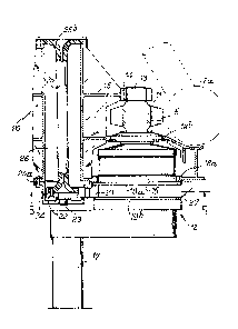
With reference now to Fig. 4, a motor drive mechanism
12 will now be described in more detail.
Fig. 4 shows partly the pillar 2a of a leg provided
with the rack 5 which cooperates with the output gear
pinion 11. This pinion 11 is mounted on a shaft 13 which is
guided at one of its ends by a bearing 14 of a structure
15 mounted on the hull. The shaft 13 is driven in rotation
by a speed reducer 16 which is driven by an electric
motor 17.
The speed reducer 16 is pivotally mounted on the struc-
ture 15 which carries it by means of bearings 18a and 18b,
whereby a certain angular movement of said speed reducer,
and therefore of the corresponding output pinion 1~ is
possible during the descent and the laying of the leg, as
will be seen hereinafter.
Further, the speed reducer 16 is connected to a me-
c*anism 20 for absorbing energy, in particular at the mo-
ment of the ccntact of the leg with the sea bed.
For this purpose, the speed reducer 16 includes ex-
ternally two flanges l9a and l9b between which is fixed atoothed sector 21 which cooperates with a gear puinion 22
(Fig. 5) mounted on a shaft 23 which is rotatively guided
by a housing 24 fixed to the structure 15. Further, the
pinion 22 is mounted on the end 25a of an elastically yieldable
support element which, in the e~x~iment shown in Fig.4,is cons-
tituted by a torsion bar 25 placed in a cavity 26 provided
inside the structure 15. The other end 25b of the torsion
:: : : ' ' ':
:: : . :
1~27278
-- 6 --
bar 25 is immobilized on the structure lS.
The torsion har 25 may be made from steel or a com-
posite material of high strength. It may also be formed
by a tube of composite material obtained by winding and
composed of glass threads and epoxide resin.
The speed reducer 16 also includes on the opposite
side to the toothed sector Zl a lug 27 for limiting the
angular movement of the speed reducer between two end-of-
travel stops 28a and 28b (Fig. S).
Each system for shifting and suspending the hu~l 1 of the
oil platform is therefore arranged in this wayO
The whole of the platorm is therefore brought in a
floating state to the drilling or production site and the
legs 2 are lowered until a contact with the sea bed. For
lS this purpose, the electric motors 17 therefore drive through
the speed reducers 16 the output gear pinions 11 which
are meshed with the racks S. During the descent of the
legs 2, the electric motors 17 act as brakes.
When the leg 2 comes into contact with the sea bed
at the end of the descent, the impact may be very violent
bearing in mind the movements of the hull under~the effect
o the swell~ The shock is therefore transferred to the
output gear pinions 11 by the rack 5 which causes the speed
reducers 16 to rotate in the bearings 18a and 18b. Each
speed reducer 16 in rotating drives the toothed sector 21
which in turn drives the gear pinion 22. The reaction
torque is therefore transmitted to the various torsion
: i : : :: . ...
~: ,:, ~ , : : ,: - , :
,: ; . : .
.
.
1327278
bars 25 which are deformed and act as suspension elements
of the leg 2 on the hull 1.
This suspension device absorbs the shock at the mo-
ment of contact of the leg on the sea bottom b y a pro-
gressive absorbtion o energy in a travel determined by thestops 28a and 28b between which the lug 27 of the speed
reducer 16 of each motor driven mechanism travels~ This
~; travel allows, owing to the articu1ated mounting of the
speed reducer 16 on the structure, a certain rotation of
the output gear pinions 11 at the moment of impact and thus
allows the racks 5 and therefore the legs 2 to oscillate
~ and to be stabilized by progressively transmitting the
:: load of the platform to the sea bed.
: ~ In the embodiment shown ln Fig. 6, the elastically
yieldable support element of the energy absorbing mechanism
20~is constituted by two torsion bars 30 and 31 connected
in series and placed in the cavity 26 of the structure l5.
The toothed sector 21 of the speed reducer 16 is engaged
with the gear pinion 22 mounted on the shaft 23 which is
20 -rotatively guided by a housing 32 fixed to the structure 15.
The gear pinion 22 is mounted on the end 30a of the first
P torsion bar 30. The other end 30b of this first torsion
bar 30 is connected to a gear pinion 33 which is meshed
with a gear pinion 34 mounted on the end 31a of the second
torsion bar 310 The gear p1nions 33 and 34 are each
mounted on a respéctive shaft 35 and 36 rotatively guided
by a rear housing 37 fixed to the structure 15. The end
,., ~. :, ...:
~: . :. : i, i .- : .:
1327278
31b of the torsion bar 31 is immobilized on the front
housing 32.
The reaction torque applied to the speed reducer 16
is transmitted through the toothed sector 21 and the gear
pinion 30 to the first torsion bar 30 which is deformed.
In deorming, the first torsion bar 30 drives the gear pi-
nions 33 and 3a and this causes the deformation of the
second torsion bar 31,one of ~he ends of which is immobilized
on the structure. The torque is therefore taken up by
the two torsion bars 30 and 31 which permits an absorbtion
o the shock at the moment of contact of the leg on the
sea bed.
With this arrangement of two torsion bars, the over-
all size is reduced and there is a great flexibility of
shock absorbtion. If required, the number of torsion bars
connected in series may be multiplied.
~; In the embodiment shown in Fig. 7, the end 40a of the
torsion bar 40 has, as before, a gear pinion 22 which coo-
perates with the toothed sector 21 fixed to the speed re-
ducers 16. On the other hand, the other end 40b of the
torsion bar 40 is provided with a pre-setting system 41 of
the torsion of said bar. This pre-setting system 41 com-
prises a motor-speed reducer unit 42 drivingly engaged with
a gear wheel 43 which is meshed with a toothed ring 44
fixed to the end 40b of the torsion bar. This pre-setting
system may be advantageously constituted by a worm and
worm wheel assembly.
~` 1327278
The pre-setting system permits, by means of the
gear wheel 43 and the ring gear 44~a pre deformation of
the torsion bar 40 and a modi*ication of the position o
the neutral point of the lug 27 limiting the angular mo-
vement o the speed reducer between the two end-of-travel
stops 28a and 28b (Fig. 5).
The energy absorbing mechanism 20 shown in Fig. 8
comprises a torsion bar 50 formed by a tubular sleeve com-
posed of an elastomer or a like elastic material in which
there may be incorporated rigid washers. As in the pre-
ceding embodiments, the end 50a of the torsion bar 50 is
mounted on the gear pinion 22 driven by the toothed sector
21 and the opposite end~50b is immobilized on the struc-
ture 15.
Further, this torsion bar may also be formed by a
solid cylinder composed of an elastomer or a like elastic
material, or of a laminated material formed by a juxtapo-
sition of washers composed of an elastomer or rigid
washers.
~ The end SOb of the torsion bar 50 may also be associa-
`ted with a torsion pre-setting system.
It can be seen that the various arrangements just
described permit a reduction in the stresses due to shocks
in the structure, and above all in the gearing of the
speed reducers, and also a control of the balancing of the
loads on all of the output gear pinions of said speed
reducers.
- ~ , .
~327278
-- 10 --
Moreover, the suspension device according to the in-
vention permits an equalization of the torques between
all the speed reducers of the system for shifting the
legs relative to the hull, and thus affords the possibility
of the laying of the platform under very severe sea con-
ditions, and therefore within a wider meteorological range
which considerably reduces the costs of installation.
Furtheremore, this device also affords the possibi-
lity of measuring the load applied to the output gear pi
].0 nions of the speed reducers by disposing for example a mea-
suring element on the end of the torsion bar opposed to
the driving gear pinion and measuring the angle of rota-
tion of the rotating end of the torsion bar, said angl~
being proportional to thls load.
, .
,
.