Note: Descriptions are shown in the official language in which they were submitted.
1327606
PROCESS FOR THE PRODUCTION OF UREA
BACKGROUND OF THE INVENTION
1. Field of the invention
~his invention relates to a urea production process by
synthesis where ammonia (NH3) and carbon dioxide (co2) are
reacted under high pressure and at a high temperature to f orm
urea, ammonium carbamate, water and unreacted compounds, and
in which reacted effluents discharged from the said synthesis
reactor are treated to decompose the carbamate and recover
the unreacted compounds in order t~ recycle them to the
reactor; more specifically, the inVention relates to a urea
production process with low energy consumption, high reaction
yields and low residual content of unreacted material in the
urea produced.
2. Description of the Prior Art
It is known that high reaction yields are favoured by a
high ammonia excess (compared with the stoichiometric ratio),
which require, however, a high reactor operating pressure. A
high synthQsis pressure is unfavourable to the efficient
separation of unreacted compounds from the urea solution
obtainQd~ In consequence before the so-called "stripping"
technology, in which the bulk of unreacted components are
sQparated in steps opQrating at reactor pressurQ by using a
stripping agent (NH3 and/or CC~), became known pressure was
drastically reduced downstream the reactor to achieve the
efficient separation of the unr~acted material.
In stripping processQs the reactor operating pressure has
been drastically redu~ed, to the dQtriment of yields, to a
compromise pressure in order to achieve the isobaric
separation of the unreacted material by using a stripping
agent.
Several processes have been recently described, aiming
to combine the advantages of high reaction yields typical of
conventional processes with the advantages of stripping
processes.
Among the most recent processes of this kind, the
following might be mentioned:
X ~
`` ~ 3 ~ 13276~6
.
A) USA Paeent No. 4.208.347 (Montedison); B) Japanese Patent Application
PCTlJP 70/00192 ~Mitsui T. and Toyo E.); C) U.S.A. Patent # -
~
4,269,~97 (Ammonia Casale SA); D) U.S.A. Patents 3,984,469 and4,137, 262 (Snamproget~
Ic should be stated in advance that the forerunner of the above patent
documents should be considered to be British Patent No. 1.1185.944
(Chemico) in which treatment of the bulk of the solution discharged from
a high yield reactor is in two steps in series (only the first or both
isobaric with the reactor); the bulk of the carbamate is separated in
the first step also with the help of fresh stripping NR3 and the residual
NH3 is separated in the second step with the introduction of fresh
stripping C02. `'`:'
The above processes according to A~, B) and C) have, downstream a urea
reactor, t~o separation steps in series in ~hich the unreacted compounds
are separated "selectively": more specifically in A) and D) the bulk -
of ehe carbamate is separated in the first step and residual ammonia is
separated in the second step using C02 as stripping agent in C) the
bulk of the ammonia is separated in the first step and the carbamate is
decomposed in the second step possibly with the help of C02 as stripping
agent either in the second or`in both steps. This is achieved by
operating under critical conditions in both separation steps. In the
process according to B) there are two separation steps downstream a
hi~h-yield reactor, in which the unreactet compounds are separated.
As in processes A~ and D), a falling film exchanger is used in the first
step, using NH3 as stripping agent. Similarly to A~ and D), therefore,
the bulk of the carbamate is selectively separated in the first step,
while in the second seep the residual~reactants are separated, using
C2 as scripping agent; ~a falling-film exchanger is used in both
steps. In process D), aQ a~ variation from process A), the second
treatment step is not isobaric with the rese of the loop (reactor
in a single step isobaric ~ith the first treatment step).
:
' ' ' ' ,~ '~' '
1327~06
In process A) all the vapours ~NH3 + C02) obtained by
decomposing carbamate (prevalently in the first step) are
separated and recycled directly to the reactor (and, where
the latter is in two sections, to the upper section), while
the vapours obtained in the second step (residual free
ammonia and stripping co2 fed to the falling film exchanger)
: are fully condensed and recycled to the reactor lupper
3 seetion in the case of a two-section reactor).
In process B) the vapours separated in the two steps
downstream a eonventional high yield reactor are mixed and
eondensed before being reeyeled in solution form to the
reactor by means of an e~eetor. In patent A), although a
reactor in two superimposed sections is deseribed in one of
the alternatives, the two streams of the material separated
in the tw~ steps in the s~ries downstream the reaetor are
both recycled to the main reactor (upper section in the ease
of a two-section reactor) or simply to the single piece
reaetor. Even if, as is known, the two-step reactor i8
adopted to exploit the concept (known per SQ) of using
j several reaction zones with different NH3/C~ molar ratios in
order to optimize transformation yields, it does not solve
satisfaetorily from an economie point of view the important
problem of heat balance control ~operating temperature) in
the two reaetion zones; this problem, up the present, has
been the main obstaele preventing the effeetive application
of these systQms.
The heat balanee problem becomes even more critical in
high-yield reaetors where it is neeessary to operate with
high NH3 exeesses, involving a greater lack of heat.
Aeeording to proc:esses A) and D), moreover, since all
gaseous eompounds from the seeond treatment step are
condensed before being reeycled to the reaetor, it is
ab~olutely imperative, by reason of the reactor's heat
balance, that practieally all the carbamate should be
separatQd in the first step, thus obtaining a suf~icient
amount of CC~ in the gas stream recycled directly as such to ~.
the reaetor, which ensures that sufficient heat is produced
~ " .
~3276~
as reaction heat from forming carbamate. To achieve such
selective separation of the bulk of thiocarbamide in the
first step it is nevertheless necessary to use complex and
expensive falling film exchangers and large quantities of
stripping agent (NH3) which, as described above, must be
expensively evaporated.
In effect in process A) there is also compensation for
the insufficient heat balance in the two reaction steps by
introduction in both steps of fresh f~ed ammonia, preheated
and/or evaporated, thus using up energy and involving complex
controls. It should also be pointed out that part of the
fresh feed ammonia must also be sent to the first reactor
effluent treatment stage as stripping agent to decompose the
bulk of the carbamate. Both reaction zones therefore have
t 15 insufficient heat, so that all the fresh feed ammonia must be
uneconomically preheated and/or evaporated.
In process B) the problem of the reactor's heat balance
is ignored since all the carbamate (exothermic reaction,
? hence main source of heat3 forms outside the reactor.
In process C) this critical aspect, which nevertheless
conditions and defines the recycling system for the unreacted
compounds from the two treatment steps, is not described
(because outside or not homogeneous with the essential aspect
of the specific treatment according to the invention).
Both in process A) and process B) the high synthesis
pressure required to produce high yields heavily conditions
ths separation efficiency of the unreacted compounds in the
two treatmerlt steps operating isobarically with the reactor.
3 o ~=~9~INV~IS~3.
The main ob~ect of this invention is to provide a
process which does not suffer from the above-mentioned
drawbacks and successfully combines a high-yield synthesis
reaction with subsequerlt efficient separation of the
compounds not transfor~ed into urea in such reaction.
Another object of the invention is to provide a process
which, while providing a high-yield synthesis reaction, can
at the same time carry out the efficient separation of the
...
1~27606
unreacted compounds and control the heat balance without the
additional consumption of energy. A further object of the
invention is to provide a process in which optimal reaction
conditions (NH3/CO2 ratio, reaction temperature etc.) upstream
the reactor are controlled by controlling treatment
conditions downstream the reactor.
Finally, yet another object of the invention is to
provide a process in which the pressure is so distributed in
the various steps as to result in a high degree of operating
lo flexibility and economy. These and other objects are
achieved with the process according to the invention,
characteri2ed by t~e fact that Since the synthesis reaction
is carried out in two zones in series each with a different
NH3/CC~ ratio, the whole of the raactant (NH3~CO2) stream
leaving the second treatment step is recycled to the first of
such zones after partial condensation, while at least part of
the gas (NH3+~) stream leaving the first treatment step is
recycled directly to the second reaction zone, the amount of
gas leaving the first and second treatment step being
controlled in such a way as to ensure optimal NH3/C02 ratios
and reaction temperatures in the two reaction zones.
A further feature of the invention i8 that the gas
strea~ recovered in the sQcond treatment step is partially or
totally condensed and a portion of vapors from the first
and/or second treatment StQp iS sent directly to the first
reaction zone so that the residual vapors provide by
reaction, in both cases (total or partial condensation) the
heat necessary to maintain at optimal value the temperature
in the first reaction zone; in the same way, the first
treatment step is controlled so as to produce the right gas
to maintain at optimal value the NH3/CO2 ratio and temperature
in the second reaction zone. Fresh NH3 or CO2 may possibly be
introduced in the first treatment step.
A particularly advantageous embodiment of the invention
35 i8 that the operating pressure in the second reaction zone is
equal to the pressure in the first treatment step while the
pressure in the first reaction zone is equal to the pressure
in the second treatment step and in the condenser, and
.: : - ~ .. . . .... .... ... . ..
1327606
preferably lower than the pressure in the second reaction
zone and in the first treatment step. A high degree of
operating flexibility and considerable energy saving are thus
achieved.
BRIEF DESCRIPTION OF THE DRAWINGS
The various aspects and advantages of the invention
will become more apparent from the description of the
embodiments shown in the attached drawings and from the
following examples, the embodiments and examples being an
illustration and not a limitation of the invent~on. In said
drawings fiyure~ 1 to 4 are block diagrams or schemes of the
preferred process emkodiments.
~ETAI~ED DESCR~PT~ON OF THE PREFERR~p EMBODINENTS
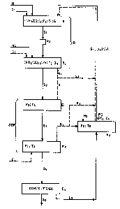
In the drawing in Fiq~ 1 the letter R indicates the
whole synthesis reaction zone and the lQtters STR indicate
the whole separation treatment zone for the stream from R.
This whole reaction zone R is now divided into at least
tow reaction zones: Rl where reaction between fresh reactants
Nl (indicating the NH3 feed stream) and C~ (indicating the CO2
feed stream) and the recycle stream (gas + liquid) G4 ~ Ll (or
L'l with G~ = O) takes place with molar ratio (NH3JC~)I.
pressure P~, temperature T~ and therefore urea transformation
yield Ql; R2 in which the synthesis reaction of stream Sl from -
R~, with the possible addition of fresh ammonia feed N2 and/or
carbon dioxide C3 is completed at molar ratio (NH3/Co2~ 2,
pres~ure P2, temperature T2 and yield Q2. The effluent S2 from
the second reaction zone R2 now undergoes a quantitative STR
treatment, also in two steps, to decompose the carbamate and
separate the unreacted compounds, consisting of: step E
where at selected operating pressure P3 and temperature T3
(bQsidQs residence time) an amount of gas G is separated, the
bulk of which is recycled as stream G~ directly to the second
reaction step R2 (the residual part G2, if any, being sent
through circuit RCI and/or directly to the first zone R~; step
~ in which effluent S3 from the first treatment step Et is
13276~
treated at pressure P4, temperature T4, preferably
countercurrently with fresh carbon dioxide C2 to recover all
the residual unreacted materials G3 which after partial
condensation in E3 (operating at pressure P5 and temperature
T5 with the possible addition of fresh ammonia N3) are
recycled as vapour-liquid mixture G~ + L~ to the first
reaction zone R~. Alternatively condensation in E3 may be
total (G4 = o, recycle RC't = L'l) and a portion of vapours G3
(G'3) is sent directly to the first reaction zone Rl.
Effluent S~ from E2 is then conventionally treated in E~ where
the required final product S5 iS separated and solution ~ is
recycled to condenser ~. Nith the process according to the
invention an entirely isobaric scheme where P~ = P2 = P3 = P4 =
P5, or preferably a non-isobaric scheme can be achieved.
With a non-isobaric schema, to the advantage of maximum
efficiency and flexibility R2 and E, may be kept at the same
pressure P = P2 = P3 ~ and R~, E2 and ~ at the same pressure P'
~' ' P~ ~ P~ = P5, P being higher than P'. The high pressure "P"
is therefore maintained only in a small portion of the plant,
r 20 with considerable savings in energy consumption and plant
investment costs. At the same time as high pressure P2, a
high (NH}/C02)2 ratio will also be selected so as to achieve
the highest yields.
According to the main feature of the invention, since
the decomposition and separation treatment of the compounds
unreacted in E~ and E2 is quantitative, such treatment is
controlled so that both in the first (E~) and in the second
(~) StQp can be obtained directly those gas streams (G) and
(~) which sent separately to the first and second reaction
zone ensure optimal (NH3/CO2)1 and NH3/COl)2 ratios and optimal
heat kalances to achieve maximum yields and correct reaction
temperature.
These high yield!3 are advantageously achieved by
minimizing the pressure in reactor R and, consequently, the
pressure of the two steps in the isobaric scheme with maximum
sQparation efficiency o~ the unreacted materials and minimum
energy consumption and investment costs in the non-isobaric
.
13276~6
scheme where on the second reaction zone and the first
trea~ment step operate at higher pressure.
Another advantage of the invention lies in the fact that,
- since the separation treatment is quantitative, the first
step may be carried out inexpensively, i.e. without having to
- use a falling film separator.
-
1. Non-isobaric operation (Fig. 2 and Table 1)
To the first reaction zone Rl operating at Pl = 160 bar
and Tl = 182C are fed a 32.32 mole NH3 stream Nl at 40c, and
the liquid-vapour mixture G~ + Ll containing 20 moles of Co2,
30.68 moles of NH3, 6 molas of H20 at 174C; the molar ratio
(NH3/C~)I is equal to 3.2 and the conversion yield Ql of CO2
into urea is 60~. The urea solution S~ feeding the second
reaction zone R2 consists therefore of 12 moles of urea, 8
mol~s of C02, 40 moles of NH3 and 18 moles of H20.
To the second reaction zone R2, operating at P2 = 185
bar and T2 = 192C, in addition to solution Sl from the first
zone Rl fed fcr example through pump Po to overcome the
pressurQ differential (from P~ = 160 bar to P2 = 185 bar) are
fed vapours G~ at 196C containing 2.2. moles of C~ and 36
moles of NH3 and 1 mole of H20 coming from the first treatment
step El also operating at P3 = 185 bar an~ T3 = 196C. In the
second reaction sone R2 the molar ratio (NH3/CO2) 2 is 4.5 and
C02 reaction yield Q2 is 75%. The urea solution S2 containing
16.66 moles of urea, 5~54 moles of CO2, 66.68 moles of NH3 and
23.66 moles of H20 feeds the first treatment step El where at
P3 ~ P2 ~ 185 bar and at T3 = 196C are separated 2.2 moles of
C02, 36 moles of NH3 and 1 mole of H20, which are fed directly
to the second reaction zone R2. Solution S3, containing 16. 66
moles of urea, 3.34 moles of C02, 30.68 moles of NH3 and 22.66
moles of H20 feeds the second treatment step E2 operating at
p4 - Pl 8 160 bar and T4 = 185C, where by using 16 . 66 moles of
co~ countercurrently (indicated by C2 in the drawing) are
sQparated from the urea solution 1.84 moles of CO2, 27.48
moles of NH3 and 2 moles of H20.
-~r
.~1 `. '
i3276~6
The gas from ~ consisting of 18.5 moles of cO2, 47.48
moles of NH3 and 2 moles of H~o feeds condenser ~ (carbamate
condenser), also fed from solution ~, 1.5 moles ~f co2, 3.2
moles of NH3 and 4 moles of H20, discharged from final
treatment system E~ where the last traces of co2 and H20 still
contained i solution S~ discharged from ~ are finally
separated. The mixed phase (vapours ~ carbamate solution) G4
+ Ll at 160 bar and 175C formed in condenser E3 is recycled
by gravity to the first reaction zone R~. It contains 20
moles of C02, 30.68 moles of NH3 and 6 moles of H20.
2. Isobariç o~eration (Fig. 3 and Table 2)
To t~e first reaction zone Rl, operating at Pl = 160 bar
and Tl = 180C , are fed 25.82 moles of NH3 (stream Nl) at 40C
and the liquid-vapour mixture G~ + ~ containing 21 moles of
C02, 37.18 moles of NH3 and 6 moles of H20 at 175C; the molar
ratio (NH3/CO2) 1 is 3 and the conversion yield Ql of C2 into
urea is 57%. The urea solution Sl which feed~ the second
reaction zone R2, therefore, consists of 12 moles of urea, 9
moles of C02, 39 moles of NH3 and 18 moles of H20.
To the second reaction zone R2, operating at P2 = Pl =
160 bar and T~ = 190C, are fed, besides solution Sl from the
first reaction zone Rl, vapours Gl at 194C containing 2.8
moles of C2~ 24.7 moles of NH3 and 1 mole of H20 coming form
the first treatment step El also operating at P3 = P2 = P- =
160 bar and at T3 - 194C.
To the second r~action zone R2 are also fed 7.5 moles
of NH3 (stream N2) at 40C and the molar ratio (NH3/CO2)2 is 4;
the CY~ conversion yield Q2 iS 70%-
The urea solution ~ containing 16.66 moles of urea,
7.14 moles of C2~ 61.8lB moles of NH3 and 23.66 moles of H20 ~ :
feeds the first treatment step El where at P3 = P2 = 160 bar
at T3 ~ 194C stream Gl is separated, such stream containing
2.8 moles of C02, 24.7 moles of NH3 and 1 mole of H20 fed
directly to the second reaction zone R2. Solution S3
containing 16.66 moles of urea, 4.34 moles of C02, 37.19
moles of NH3 and 22.66 moles of H20, feeds the second
: ~ . . . . . - : . . .. . . . .
13276~6
11
treatment step ~ at P4 = P3 = Pl = 160 bar and at T4 = 185C,
where by using stream C2 containing 16.66 moles of C02
countercurrently, 2.84 moles of C02, 33.98 moles of NH3 and 2
moles of H20 are separated from the urea solution. Gas G3
discharged from E2 consisting of 19.50 moles of C02, 33.98
moles of NH3 and 2 moles of H20 at P4 = P4 _ p3 = Pl = 160 bar at
T5 = 190C feeds the condenser E3 (carbamate condenser), also
fed by solution ~ (consisting of 1.5 moles of C02, 3.2 moles
of NH3 and 4 moles of H20), discharged from the final
o treatment system S5 where the last traces of c~ and H20,
still remaining in the solution from ~, are finally
separated. The mixed phase (vapours ~ carbamate solution) G4
+ ~ at 160 bar and 175C which formed in ~ is recycled to
the first reaction zone Rl. It contains 21 moles of c~,
37.18 moles of NH3, 6 moles of H20. All the ~trQams circulate
in the isobaric system by qravity.
3. Non~isobaric operation ltotal condensation
in the carbama~e condenser) ~Fig. 4 and Table 3~
As example 1, but with total condensation of part of
the recycle vapours sent to the first reaction zone R~, while
the balance of the recycle vapours is directly recycled to
the reactor. In this case only a solution is recycled from
condens~r E3 to the reactor, without vapour phase L'~ (G~ = 0)
and the condenser is fed with only part of gas G3, part of
the same G ~3 being sent directly to the reactor.
' .
.: . ~ . .. .. - . - .. . .
~ -- 1 2 --
1327606
~- P. O O ~n
¢
. o
~ o. o ~ ~ o
, , . ;, , ,
`D '
~ a ~ ~O
a~ `
U C
Q' O U~ ~ ~ ~ ~ :
~ ~ O
.
.
~ ~ ~ o ~
P
`D ~ 0~ `D ~ ' `
-- ~ ~ ~ ~ CO o W ,:
.`: . ' -
O ~:r O `D ~O . ' '
`.'-, '`' '"
-- C o ~ ~ ~ ~
o o
~t :; :
r" ~" ,D ¢ : ~
Ptt E' t~
' ` ' ' ` ' " ' :;
1 32 76 0 6
U~ <, , `
o- o
o , ,
o
t~C ~ æ, ~
V~ ~ O~
O
~-1 O' O ~ ~ ~ 3 `t~
'~ ~ -
C~ O O ~ ~ ~ ~
-- ~ ~ -.
Z~ C' O O
~ -- I~
~ ~O ~ I ~ -- ~D ,. ,
., .
. . .
-- O O O ~ ~ ~ ~ '-'':
~ -- -- " " .
-- O O O ~ ` ~,~
,~ Z X~ " ~,
: '' :..
:,
_
` - 14- 1327606
~,~ ~ o o
o
C 'D
~,,
~ O'o u~ ~ ~ ~ ~D
V~ ~ `C ~ ^ ^ ^
r~ O
oo ~ ^
o
~ . . `
E~ :
.. .
.
U~ ~ ~ ~ o ~ ,
o~ .,
CS~ , ~ ~ ~ :, .. `
CO,~ ,
~~ ` :
~ o ~ ~~ o to ..
- ` :.
. ~...~..
:-- ~ ~ ~
t, ~,. ..
.. ~ .
o~ ~ ~
. . ~.., ~ ....
~: ... . ;.
.,. . ,: .:: .
;: .. `.