Note: Descriptions are shown in the official language in which they were submitted.
13279~
CYCLONE SEPARATOR _AVI~G wATER-STEAM COOLED WALLS
This application is related to Canadian Serial No.
5S9,794 filed FebruarY 25, 1988.
Backqround of the Invention
This invention relates to a cyclone separator and,
more particularly, to such a separator for separating
solid fuel particles from gases discharged from a
combustion system or the like.
Conventional cyclone separators are normally provided
with a ~onolithic e~ternal refractory wall which is
abrasion resistant and insulative so that the outer casing
runs relativelY cool. Typically, these walls are formed
by an insulative refractory material sandwiched between an
inner hard refractory material and an outer metal casing.
In order to achieve proper insulation, these layers must
-- 1327~
-
--2--
be rel~tively thick which adds to the bulk, weight, and
cost of the separator. Also, the outside metal casing of
these designs cannot be further insulated from the outside
since to do so could raise its temperature as high as
1500F which is far in excess of the maximum temperature
it can tolerate.
Further, most conventional cyclone separators require
relatively expensive, high temperature, refractory-lined
ductwork and expansion joints between the reactor and the
cyclone, and between the cyclone and the heat recovery
section, which are fairly sophisticated and expensive.
Still further, conventional separators formed in the above
manner require a relatively long time to heat up before
going online to eliminate premature cracking of the
refractory walls, which is inconvenient and adds to the
cost of the process. Also, cyclone separators of this
type may require a separate roof tube circuit which still
further adds to the cost of the system.
SummarY of the Invention
The present invention seeks
to provide a cyclone separator in which heat losses are
reduced and the requirement for internal refractory
insulation is minimized.
'~ .
. ~ :
~ .:
- ~ .
1327~
--3--
The present invention further seeks to provide a cyclone
separator of the above type in which the need for expensive,
high-temperature, refractory-lined ductwork and expansion joints
between the furnace and the cyclone separator and between the
latter and the heat recovery section are minimized.
More particularly, the invention pertains to a cyclone
separator comprising an inner cylinder, an outer cylinder
extending around the inner cylinder in a coaxial relationship to
define an annular chamber between the two cylinders, the outer
cylinder comprising a plurality of tubes extending vertically and
circumferentially in a parallel relationship for at least a
portion of their lengths. A ring header is connected to the
lower ends of the tubes for supplying cooling fluid to the tubes
and a hopper extends downwardly from the ring header. Means is
provided for directing gases containing solid particles through
the annular chamber for separating the solid particles from the
gases by centrifugal forces, the separated gases exiting through
the inner cylinder and the separated solids falling to the
hopper. The upper end portions of the tubes are bent to form a
roof for the annular chamber and to form an outlet chamber for
the separated gases and there is means for passing water or steam
or a steam and water mixture through the tubes to cool the outer
cylinder.
In one aspect the outlet chamber has a floor and wherein the
inner cylinder is disposed so that an upper portion of the inner
cylinder extends above a plane formed by the floor of the outlet
A~
, . . . .. .... . ~ , .. , .,., , . ~ . .. . ...
. .. . .
.. . ~ , . .. .
, . ~ . ~ . . . .. .
.. ~ . . . ; . .. . ..
.. . , , ~ . ~ . . .
^\
13279~
--4--
chamber.
In another aspect a continuous fin extends between adjacent
tubes and a plurality of tiles extend adjacent an inner wall of
the outer cylinder with means connecting the tiles to the fins.
Refractory is disposed between the fins and the tiles.
In a still further aspect a continuous fin extends from
corresponding portions of adjacent tubes to form a gas tight
structure.
Further still in another aspect each of the bent upper end
portions of the tubes include a horizontal portion extending from
the outer cylinder to the inner cylinder, a vertical portion
engaging a corresponding portion of the inner cylinder along the
length of the vertical portion and another horizontal portion
extending outwardly from the inner cylinder to form a floor of
the outlet chamber.
Brief Description of the Drawings
The above brief description as well as further objects,
features and advantages of the present invention will be more
fully appreciated by reference to the following detailed
description of presently pre-ferred but nonetheless illustrative
embodiments in accordance with the present invention when taken
in conjunction with the accompanying drawings wherein:
Fig. l is a schematic view of the cyclone separator of the
present invention and an adjacent heat recovery area of a boiler
system
Fig. 2 is an enlarged perspective view of the tubes forming
the outer cylinder of the separator of Fig. l; and
.. ' : ' ' ' . : . - '
`"
~ _5_ 1327~6
Fig. 3 is an enlarged, cross-sectional view taken
along the portion of the wall of the outer cylinder of
Fig. 3 designated by the line 3-3, and showing the
insulative materials surrounding the tubes.
Description of the Preferred Embodi~ent
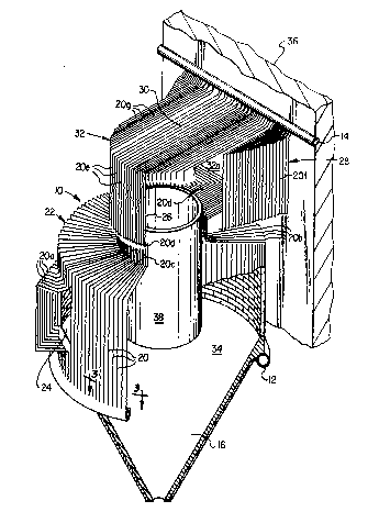
Referring to Figs. 1 & 2 of the drawings, the
reference numeral 10 refers in general to the cyclone
separator of the present invention which includes a lower
ring header 12 and an upper header 14. The header 12
extends immediately above, and is connected to, a hopper
16 disposed at the lower portion of the separator 10.
A group of vertically-extending, spaced, parallel
tubes 20 are connected at their lower ends to the header
12 and extend vertically for the greater parts of their
lengths to form a right circular cylinder 22.
A portion of the tubes 20 are bent out of the plane
of the cylinder 22, as shown by the reference numerals
20a, and, as shown in Fig. 2, approximately half of these
bent tube portions are bent away from the other half to
form an inlet passage 24 to the interior of the cylinder
for reasons that will be described.
At the upper end of the cylinder 22 the tubes 20 are
bent radially inwardly, as shown by the reference numeral
20b, and then upwardly as shown by the reference numeral
-6- 1327~
20c, to define a circular opening which, of course, is of
a diameter less than that of the diameter of the cylinder
22. The tubes 20 are then bent radially outwardly as
shown by the reference numeral 20d, and a portion of these
bent tube portions 20d are bent upwardly as shown by the
reference numeral 20e. As better shown in Fig. 2 the best
tube portions 20e form approximately one-half of a right
circular cylinder 26. The remaining portions of the bent
tube portions 20d extend horizontally are bent at right
angles in a horizontal plane, and then vertically, as
shown by the reference numeral 20f, to form two vertically
extending, spaced walls one of which is shown by the
reference numeral 28. The tube portions 20e and the
vertically extending tube portions 20f are bent to form
lS horizontal tube portions 20g which form a roof 30 for an
enclosure 32 defined by the tube portions 20d, the partial
cylinder 26 and the walls 28.
The enclosure 32 has an outlet opening 32a which
discharges to a heat recovery area, shown in general by
the reference numeral 36.
The lower header 12 can be connected to a source of
cooling fluid, such as water which passes from the header
12, through the tubes 20, and into the upper header 14
.- , ~................ ,
,
_7_ iq 2 ~
which is converted to a header 37 rorming a portion of the
water flow circuitry of the heat recovery area 36.
An inner pipe, or barrel, 38 is disposed within the
cylinder 22, is formed from a solid, metallic material,
such as stainless steel, and has an upper end portion
extending slightly above the plane of the tube portions
20d. The pipe 38 extends immediately adjacent the tube
portions 20c, and its length substantially coincides with
the inlet passage formed by the bent tube portions 20a.
Thus, an annular Chamber 3~ is formed between the outer
surface of the pipe 38 and the inner surface of the
cylinder 22, and the tube portions 20b form a roof for
said chamber.
The tubes 20 are disposed between an insulative
material and an erosion preventing structure which are
omitted from Fig. 2 for the convenience of presentation
but which are shown in Fig. 3. More particularly, a fin -
40 is welded to, and extends from, the corresponding walls
of each pair of adjacent tubes 20. A lagging, or panel 42
of a lightweight material, such as aluminum, is provided
in a slightly spaced relationship to the plane of the
tubes 20, and a heat insulative material 44 is disposed
between the outer surface of the tubes 20 and the inner
wall of the lagging ~4. ~ plurality of tiles 46 extend
adjacent the inner wall of the cylinder 22 and are
, . . - .
.,. ~ . .
--- 1327~6
connected by anchors 48 extending from the inner walls of
the tubes 20. A layer of refractory material 50 is
disposed between the tiles 46 and the tubes 20.
In operation, and assuming the separator lO of the
present invention is part of a boiler system including a -
fluidized bed reactor, or the like, disposed adjacent to
the separator, the inlet passage 24 formed by the bent
tube portions 20a receives hot gases from the reactor
which gases contain entrained fine solid particulate fuel,
ash, limestone, etc. from the fluidized bed. The gases
containing the particulate material thus enter and swirl
around in the annular chamber 34 defined between the
cylinder 22 and the inner pipe 38, and the entrained solid
particles are propelled by centrifugal forces against the
inner wall of the cylinder 22 where they collect and fall
downwardly by gravity into the hopper 16. The relatively
clean gases remaining in the annular chamber 34 are
prevented from flowing upwardly by the roof formed by the
tube portions 20b and their corresponding fins 40, and
thus enter the pipe 38 through its lower end. The gases
thus pass through the length of the pipe 38 before exiting
from the upper end of the pipe to the enclosure 32 which
directs the hot gases radially outwardly to the heat
recovery area 36.
_9_ 13279~6
water or steam from an external source is passed into
the lower header 12 and passes upwardly through the tubes
20 before exiting, via the upper header 14 to the
header 37 of the heat recovery area 36. The water thus
maintains the cylinder 22 and the enclosure 32 at a
relatively low temperature.
Several advantages result from the foregoing
arrangement. For example, the separator of the present
invention reduces heat losses and minimizes the
requirement for internal refractory insulation. Also, the
bulk, weight, and cost of the separator of the present
invention is much less than that of conventional
separators. The separator of the present invention also
minimizes the need for expensive high temperature
refractory-lined ductwork and expansion joints between the
reactor and cyclone separator, and between the latter and
the heat recovery section. Still further, by utilizing
the tube portions 20b to form a roof for the annular
chamber 34 between the cylinder 22 and the pipe 38, the
requirement for additional roof circuitry is eliminated.
A latitude of modification, change and substitution
is intended in the foregoing disclosure and in some
instances some features of the invention will be employed
without a corresponding use of other features.
.
-10- 1327~346
Accordingly, it is appropriate that the appended claims be
construed broadly and in a manner consistent with the
scope of the invention therein.