Note: Descriptions are shown in the official language in which they were submitted.
- :
`- 1328004
AIRCRAFT CABIN NOISE CONTROL APPARATUS
: '
The present invention relates to apparatus for
controlling cabin noise in propeller or fan drlven aircraft.
Several proposals for reducing noise are reviewed in an
article entitled 'Strategies for reducing propeller aircraft
cabin noise' by F B Metzger in Automotive Engineering, 1981,
Vol 2, No 1, Page 5. In particular, the use of synchrophasing
to retuce noise levels in multi-engine transport aircraft is
reviewed. Synchrophasing is the automatic control of one or
more propellers to provide a fixed phase relationship between
the circumferential blade locations of the propellers in
relation to a reference propeller. By malntaining an accurate
phase relationship between the propellers the annoying beat
characteristic of unsynchronsied propellers is avoided. Cabin
noise levels may be reduced by careful ad~ustment of this phase
relationship.
There have been a number of proposals for large unducted
fan aircraft engines for operation at cruising speeds of
between 0.6M and 0.8M. Such engines are mounted at the rear of
an aircraft fuselage and a number of proposed deslgn~ include
contra-rotating forward and rearward fans. The rearwsrd fan
reduces reqidual swirl from the forward fan and improves the
overall efficiency of the engine. Cabin noise arising from the
;~ ; use of sùch engines is llkely to be a ma~or problem.
The present invention provides an improved form of-
aircraft cabin noise control using synchrophasing and activeolse contr~l ~echnl~aes.
:
1328004 - -
According to the present invention, cabin noise control
apparatus for a propeller or fan driven aircraft includes means
for varying, during flight, the phase relationship between a ~-
reference propeller or fan of the aircraft and one, some or all
of the other propellers or fans of the aircraft characterised
in that the phase relationship is varied in response to the
output from a signal processor connected to receive and analyse
signals from a plurality of transducers located inside the
cabin.
The transducers may be microphones in which case the
signal processor may form part of an active nolse control
system which generates sound waves in anti-phase with ambient
noise waves. Such a system may, for example, be as claimed in
UK Patent No 2149614. This system provides apparatus for
reducing noise in an enclosed space where the noise, 8enerated
by an external source, has a fundamental frequency fO and a
serles of harmonlcs thereof. The value of f 0 is monltored and
communicated to a signal processor ant the sound pressure level
in the enclosure 18 monitored by a plurallty of microphones and
also communlcated to the processor. The processor outputs
signals to a plurality of loudspeakers, these signals being in
antiphase with the input signals 80 as to minimise the sound
. .
pressure level in the enclosure.
Alternatively, the transducers may be mounted, for
,.:~:,
example, on a vibrating part of the aircraft which radiates
sound into the cabin. The signal processor linked to such
accelerometers may also form part of an active noise control
system slmilar to that just described. Microphones and
accelerometers may also be used in this way in combination with
one another.
In an aircraft having multishaft engines, the phase
varying means may be arranged to vary the phase relationship
between the reference propeller or fan on one shaft and a
propeller or fan on the other shaft of the same engine.
;;~ An embodiment~of the invention will now be described
~, . . .' , ', . .
132~0~4
with reference to the drawings of whlch:-
Figure 1 is a schematic diagram of aircraft cabin noise
control apparatus in accordance with the invention,
Figure 2 is a block diagram of a computer simulation of
the apparatus of Figure 1,
Figure 3, 4 and 5 are graphs showing the results of the
simulation of Figure 2,
Figure 6 is a graph showing error functions for systems
with and without active noise control.
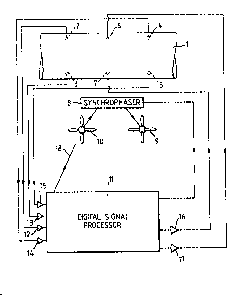
In Figure 1, an aircraft cabin 1 (only part of which is
shown) contains four microphones 2, 3, 4, 5 and two
loudspeakers 6, 7 which form the active elements of a cabin
noise control system. Outputs from the microphones 2, 3, 4, 5
are fed via amplifiers 12, 13, 14, 15 respectively to the input
of a digital signal processor, ll. A reference signal 18 at
the fundamental frequency f~ is fed into the processor ll via
a tachometer (not shown). The processor 11 has an adaptation
algorithm ln a memory store (not shown). The adaptation
algorithm 18 de6cribed in UK Patent No 2149614 and operates to
mlnimlse the sum of the squarea of the mlcrophone outputs. The
same error functlon as 18 used in the processor of the above
patent 18 used to ad~ust the synchrophase angle between a
reference propeller 10 and a 6ynchrophased propeller 9
j controlled by a synchrophaser 8 having a control input from the
¦ 25 signal processor 11. Thus the synchrophase angle 18 varled
, .
; dynamlcally durlng flight to mlnimlse propeller nolse in the
cabln over a range of flying conditlons. The following
algorlthm may be used to ad~ust the synchrophase angle to
mlnlmlse cabln nolse:-
The sampled output from the Qth error sensor, eQ(n), 1~
a linear combination of the output due to a reference propeller
dQ(n) and outputs from a further M slave propellers whose
synchrophase angle, ~ , ls controlled. The sampled outputs
due to the M slave propellers are considered as a convolution
; 35 of an effective source strength S ~n) where
~ , ' " ~ ., ; ~
1328004
\
S (n) = A cos l ~On m ~
where A = an arbitrary reference amplitude
~ = 2~ x blade passage frequency x sample time
and n = the sample number
with an effective filter having coefficient8 C
80 that
M J-l
R( ) dR(n) + ~1 ~ CRm~ Sm(n~J)
The total error~ E~ i8 defined a8:
E ~ ~ eR
R-l
So that the rate of change of E with re8pect to one
8ynchropha~e angle is:
. L
aE ~ 2 ~ e (n) aeR(n)
~m R~ m :
Now
a~ o ~m~ A ~in (~u(n-~) + ~m~
~ 5 ~ ~ CRm~ A c08 ¦~o(n i) + ~m 2)
;1 ;,' ;`::
- 1328Q04
Let k = 2 ~ so that
o
~e~(n) = ~ CJ~ j sm(n-i-k) rRm( )'
which is computed from a knowledge of S (n) and the previously
measured filter coefficients.
Thus
a~ 2 ~ e~(n) r~m(n)
and ad~usting the synchrophase angle(s) with an instantaneous
estimate of this gradient every sample gives
(n + 1) ~ ~m(n) - a ~1 eQ(n) ~m(
, 10 where a 18 a convergence coefficient.
A block dlagram of a computer slmulation of the
apparatus is shown ln Flgure 2. The simulatlon assumes four
microphones and two loudspeakers together with inputs from
a reference propeller and a synchrophased propeller. A
; 15 reference signal x(n) of the form cos( 2 ) is flltered by
`~ filters 40 and 41 which are adaptively ad~usted by the digital
~; signal processor 11 to generate secondary source contributions
yl(n) and y2(n), from the two loudspeakers. Filters 32-39 are
; employed as delays and integrators which model the cabin -~ :
acoustics. The reference and synchropha8ed propeller
~'i!';''~ ~ ' ~ contributlons are similarly filtered by filters 20-27. The
filter 42 represents the action of the synchrophaser and
introduces a phase change in the input from one propeller which
i8 determined adaptively by the action of the digital signal
: . . .
. :~ . ' ' ,
,
1328004
processor 11. Error terms are subsequently computed by means
of summers 28-31. The actual convergence behaviour of the
computer simulation may not be exactly the same as that in a
real aircraft because of the uncertainties in estimating the
S time delays in changing synchrophase angles. The results of
the simulation (see Figures 3, 4 and 5) show that an active
noise control system coupled with synchrophased propellers can
be stable. As can be ~een from Figure 3, the total error,
which ls the sum of the squares of the outputs from the four
microphones, converges to a minimum whilst a steady
synchrophase angle of between 2 and ~ is reached (see Figure
5). Figure 4 shows the corresponding variation of the filter
coefficients driving the two secondary sources during the same
~imulation run as for Figures 3 and 5.
The afore-mentioned simulation uses an error function
comprising the sum of the squares of the microphone outputs at
the fundamental blate passage frequency. However, an error
function comprising the sum of the squares of the microphone
outputs at a harmonlc of this frequency, or combinations of
harmonics, may be uset alternatively. Those skillet in the art
~; ~ will realise that the above algorithm can be readily modifiet
~ accordingly. To ensure that the total error converges to the
'; lowest minimum value possible, a test can be performed by
determining its value under a first synchrophase angle
~o ~ 25 ~contition ant then under a second synchrophase angle, ~ radians
` removet from the first. The synchrophase angle contition which
,~ ~ gives the lowest total error can be uset as a starting point
i ~ for a new convergence proceture.
For active noise control apparatus comprising a large
number of microphones and 8econdary sound 80urces, the
; computational load may be great. This load may be reduced by
u8ing the following modified algorithm:
~328004
r L
m ~m( N) ~ l ~ eR(kN)rQ (kN)
L
~ eR(kN-l)r~ (kN~
where al is a convergence coefficient, k i8 an integer and ~
is updated once every N samples. A similar modification can be
applied to the adaptation algorithm as described in UK Patent
No 2149614 for updating the filter coefficients.
It will be appreciated that the processor 11 will still
give a valld output to the synchrophaser 8 even when the
secondary source contributions are reduced to zero. The
variation of total error, E, with synchrophase angle for such a
system, A, is shown in Figure 6, together witn the correspond- ;
ing variation of E for a system B, wherein the synchrophaser
and loudspeakers are allowed to operate simultaneously. It can
; be seen that the minimum value of E for system B occurs at a
~5 different ~ynchrophase angle to that of system A. Furthermore,
`~ system B produces a lower value of E for all synchrophase
~ angle~ from 0 to 2~ radians.
., ' ~' .
~. . .. :
'";,~ ' ' , ' '' '
: : .
: .
,,.,~; :.
,~. ...
: ~ : :
, i~ i .
:': . : :
: ;~: ' '
, :;,.. , . .. j... ............ .. ..... . ... . . ..