Note: Descriptions are shown in the official language in which they were submitted.
` " ~328121
,
ACTUATOR MECHANISM FOR A HIGH-VOLTAGE CIRCUIT BREAKER
. .
, "
",
,,, FIELD OF_THE INVENTIONo
" This invention relates to a stored-spring energy type
,, actuator mechanism for a high-voltage circuit breaker.
~;, ,'.
BACKGROUND_OF THE INVENTION:
A stored-spring-energy type actuator mechanism of the
above kind is described, for example, in "Sprecher Energie Revue5'
~ ~ No. 1/86 on pages 4 and 5. In this arrangement energy for
i~ ~ switching on a high-voltage circuit breaker and for
simultaneously loading a circuit-breaker switch-off spring is
stored in a spring-energy accumulator. The spring-energy
accumulator can be loaded by means of an electric motor or by
,.. . .
hand. When the high-voltage circuit breaker is switched on and
the spring-energy accumulator and the switch-off spring
accumulator are loaded, the circuit breaker can subsequently be
switched off, switched on and switched off again without the
spring-energy accumulator having to be recharged. For reasuns of
reliability of supply, it is desirable that the circuit breaker
be able to execute ~ plurality of such switching actions even in
the event of failure of the feed network of the actuator
mechanism. In order to provide such operation, ~t has been
proposed, for example, in German O~fenlegungsschrift No.
3,540,674, to make the stored energy of the spring-energy
accumulator sufficiently high that the high-voltage circuit
breaker can be switched on several times and the switch-off
:: ,
:,
--` i328~1
- spring accumulator charged at the same tim~. As a result of the
spring characteristics, however, if the spring-energy accumulator
is not re-charged, there is substantially more energy availahle
,, for the first switching action than for subseguent switching
- actions.
This reguires on the one hand additional damping
..: .
elements for dissipating excess energy and on the other hand
appropriate dimensioning of the actuator mechanism for
.
substantial stored energies and the hlgh forces conse~uently
occurring.
SUMMARY OF THE INVENTION: -
It is an object of the invention to provide a stored~
spring-energy actuator mechanism with a spring-energy accumulator
in which energy for switching on a high-voltage circuit breaker
can be stored to an extent suf~icisnt ~or the mechanism to switch
on the circuit breaker at least one time in the event of failure
of the feed network.
In fulfillment of the above object, at least in a
preferred form of the invention, the stored energy for a single
switch-on operatlon of a high-voltage circuit breaker is stored
in a spring-energy accumulator. The energy for further switching
operations may be stored in a fluid-pressure accumulator, which
feeds a fluid motor via a control valve and by means of which
motor the spring-energy accumulator can be charged. In the known
stored-spring-energy drive, the electric motor can thus be
.~'''' , . ., ~ '-'"`
,: ., , ~, : .
: . . , :, . . , . - , .
: :. :. . . - . , , .
~ :, :, ,, , ~,
Y . . - ,. ,
~32~2~
replaced by a fluid motor which can be fed from a local fluid-
~ 1 pressure accumulator. This can be done without substantial
,~` modification to the known form of stored-spring-energy mechanism.
, ~
In a preferred embodiment of the invention, there is
connected in parallel with the fluid motor a cheek valve which is
conductive to flow in a direction from a low-pressure connection
.
to a high-pressure connection of the fluid motor and restrictive
to flow in the opposite direction. The spring-energy accumulator
., :-, .
can thus be wound up by hand, for example by means of a crank,
without having to intervene in either the fluid circuit or the
: ., ,
~-- mechanical connections between the fluid motor and the spring-
:
energy accumulator.
-~ In a further preferred embodiment, a control means is
. .,
` ~- provided for opening the valve when the spring-energy accumulator
..
is partly unloaded. This ensures immediate recharging of the
spring-energy accumulator even during or aft~r a switch-on
operation so that switch-on actions o~ the high voltage circuit
breaker can be preformed in brief succession.
; The fluid motor can be driven by means of hydraulic
.. ~ ,
' fluid which can be pumped by means of a pump through a check
valve from a low-pressure source into the fluid-pressure
accumulatox. This enables high-voltage cixcuit breakers which
~ ,~
are already installed, for example in a switch gear plant, to be
re-equipped without having substantially to change the
in~rastructure. The original electrical feeder line provided for
the electric motor for charging the spring-enargy accumulator can
,.; , '
: ,:
:~; 1328121
be connected to the pump, which only involves adjustments to the
stored-spring-energy actuator. A stored-spring-energy actuator
with a fluid motor which can be driven by means of a gas, in
particular compressed air, pumped into the fluid-pressure
; accumulator by means of a local compressor, has the same
advantages. If a central supply of pressurized gas is installed
in the switchgear plank, the fluid-pressure accumulator can be
connected directly to such supply.
-~ In a multiple-pole high-voltage circuit breaker having
a stored-spring-energy actuator mechanism for each pole, a single
local fluid-pressure accumulator can be provided for all of the
actuator mechanisms. Without great expense, feed lines can be
~ led from the fluid~pressure accumulator to the loading devices of
j~` each mechanism.
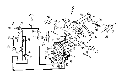
BRIEF DESCRIPTION OF DRAWIN~:
An exemplary embodiment ofjth~ invention is described
in greater detail with reference to the single drawing figure.
The drawing is a diagrammatic view of a stored-spring-~nergy
actuator mechanism having a loading device for charging a spring-
energy accumulator, which loading device has a fluid motor which
; can be fed ~rom a local fluid-pressure accumulator.
: DESCRIPTION OF PREFERRED EMBODIMENT:
A stored-spring-energy actuator mechanism 10 has
hydraulic motor 12 which acts via gearing 14 on a toothed rim 16
." ~'.
-;- 4
: .
; - - : ,. - .
~ 13~12~
of a rotatably mountsd spring cage 18. The rotational axis 20 of
the spring caga 18 coincides with the axis of a spring shaft 22.
Fixed to a laterally protruding lug 24 on the spring cage 18 is
the outer end of a spiral spring 26 having an inner end connected
to the ~pring shaft 22.
Connected for rotation with the spring shaft 22 is a
switch-on latch lever 28 supported in releasable manner on a
switch-on latch 30. By means of an electrically actuable switch-
on magnet system 32, the switch-on latch 30 can be pivoted
clockwise from the position shown in the figure into a release
position~ A cam plate 34 is also mounted for rotation on the
spring shaft 22. The distance, designated A, between the
rotational axis 20 and a radial contact surface 36 of the cam
plate 34 increases continuously, in a direction opposita the
direction of arrow B, of the cam. A transition ~rom the greatest
. ~,
,~ distance A to the smallest distance A is effected by a slightly
curved, virtually radially extending edge 37.
A bifurcated roller lever 40 is carried ~or rotation on
;` .i ~
a rotatably moun~ed roller-lever shaft 3~ arranged in parallel to
. ~ axis 20. Rotatably mounted at the free end of lever 40 is a
~; roller 42 with which the contact surface 36 of the cam plate 34
.~. can engage. The roller-lever shaft 38 arries a switch-o~f latch
:
44 at one end, and a transmission lever 46 at the other end. The
switch-off latch lever 44 is shown in solid lines in a switch-off
::~ position 0. It can be pivoted anti-clockwise into a switch-on
position I shown by chain-dotted lines. In the switch-on
~ 5
,.~ ~1
!;~ ," , .
~32~i21
position I, the switch-off latch lever 44 is supported in a
releasable manner on a switch-off latch 48 which can be pivoted
from the position shown into a release position by means of an
electrically controllable switch-off magnet system 50. Likewise
indicated by chain-dotted lines is the position of the roller
lever 40 in the switch-on position Io
The transmission lever 46 is operatively connected
through a diagrammatically indicated transmission system 52, to
a movable switch contact 54 of a high-voltage circuit breaker 67
and to a switch-off spring 58.
The above-described elements of the stored-spring-
energy drive mechanism 10 work as follows. When the switch-on
latch lever 28 is supported on the switch-on latch 30, the spring
cage 18 can be rotated through 360~, in arrow direction C by
.."
means of the hydraulic motor 12, to load spring 26. The energy
thus stored in the spiral spring 26 is suf~iciently large to
switch on the high-voltage circuit breaker 56 and at the same
time load the switch-of~ spring 58, as will now be described.
When the switch-on magnet system 32 is excited, the
switch-on latch 30 is pulled back into the rel~ase position so
that the spring shaft 22 together with the cam plate 34 is free
to rotate in arrow direction B under the influence of loaded
spring 26. ThP roller 42 thereby comes to bear on the contact
surface 36, which results in the roller lever 40 and thus the
roller-lever shaft 38 being pivoted anti-clockwise into the
switch-on position I. Once the switch-on latch lever 28 is
::; . . .
~.,
: ' ., - .: . '' ,
. . ~ . ~
- -` 1328121
- released, the switch-on latch 30 immediately returns again into
its neutral position so that, aPter a revolution of 360, the
~ switch-on latch lever 28 again comes to bear on the switch-on
: latch 30.
., As a result of the pivoting movement of the roller-
lever shaft 38, the switch-off latch lever 44, in the switch-on
position I, latches on the switch-off latch 48. Due to the fact
;- that the transmission lever 46 also pivots; the high-voltage
circuit breaker 56 is switched on and the switch-off spring 58 is
loaded at the same time.
~ The spiral spring 26 can now be loaded again by
i~ rotation of the spring cage 18 by means of the hydraulic motor
` ~ 12.
- In order to switch off the high-voltage cir¢uit breaker
56, the switch-off magnet system 50 is excited, whereupon the
switch-off latch 48 releases the switch-off latch lever 44. The
switch contact 54 of the high-voltage circuit breaker 56 is
opened by the switch-off energy stored in the switch-off spring
~` 58 and the roller-lever shaft 38 is rotated into the switch-off
position 0~ During this movement, the edge 37, running
approximately radially inwardly of the cam plate 34, provides
sufficient clearance space to accommodate pivoting movement of
~: the ~oller lever 40 and roller 42.
~;. It may be noted that a single pole of a high-voltage
~"~ circuit breaker 56 or a plurality of poles can be actuated by
~' ~J means of a single stored-spring-energy mechanism 10.
' ~
; .
'''`'' ~ ' ', , ,' , ' '".'' '
`` ~32812~
:
: A backstop or clutch device 62 acts on the output shaft
60 of the hydraulic motor 12 in such a way that rotation o~ shaft
~ 60 in a direction to load the spiral sprin~ 26 is permitted but
:. rotation in the reverse direction i5 prevented. Undesirable
unloading of the spiral spring 26 is thereby prevented. The
spiral spring 26 can alternatively be loaded by hand, by means o~
a crank 64 which can be brought into operative connection with
~: gearing 14.
,
;~ A hydraulic pump 68 driven by an Plectric motor 66 is
provided for pumping hydraulic fluid, for example hydraulic oil,
from a low-pressure reservoir 70 through a check valve 72 into a, ~
generally known hydraulic pres ure accumulator 74. In this
arrangement, the check valve 72 prevents hydraulic fluid under
pressure from flowing back to the pump 60 and the reservoir 70.
In order to prevent an excessive pressure increase in the
pressure accumulator 74, the pressure accumulator 74 is
i hydraulically connected to a pressure-relief valve 76 which opens
at excessive pressure and allows the hydraulic fluid to flow back
into the low-pressure tank 70 until the pressure in the pressure
accumulator 75 has dropped to the desired value. Also
~ hydraulically connected to the pressure accumulator 74 is a
.~ pressure relay 78 with switch contacts 80 which close when the
i . . -
~: pressure in the accumulator 74 falls below a lower limit value
".~ and open at an upper limit value. The pressure relay 78 controls
` ~ an excitation coil 82 of a switch 84 by means of which the
~.:
~ ~ electric motor 66 can be switched on and of~O
~'',''', .
~`. ` 8
: . : .
- ~328~21
- An adjustable orifice 88 for regulating the fluid ~low
: rate and also a controllable valve 90 are connect~d in series
between the pressure accumulator 74 and a high-pressure
. :: connection 86 of the hydraulic motor 12, A low-pressure
:,
connection 91 of motor 12 is hydraulically connected to the
reservoir 70. A further check valve 92 is connected in parallel
with the hydraulic motor 12 in such a way that it is conductive
in the direction from the low-pressure connection 91 to the high-
pressure connection 86 of the hydraulic motor 12 and restrictive
in the opposite direction.
The stored-spring-energy mechanism 10 is further
provided with a control member g4 in operative connection with
: .,
^ valve 90 as indicated in chain-dotted line. The control member
:~ 94 has a pivotable control shaft 96 parallel to the rotational
~ . ~
axis 20 and three single-arm levers ~2, 100 and 102. In the
position of the control member g4 shown in solid lines, the valve
90 is restrictive to fluid flow. In the position of member 94
: indicated by chain-dotted lines (and pivoted anti-clockwise
through about 45 degrees from the solid~line position,) the valve
: ~ 90 is conductive to fluid flow. The lever 98 provides a
~; connection which trans~ers the pivotal position of the control
~' shaft 96 to the valve 90, while the lever lO0, in the position
show~ by solid lines bears on a tongue 104 protruding radially
~ .
.:,; outwardly from the spring shaft 22. The lever 102, in the
.~ position shown by chain-dotted lines, is pivoted into the path of
~ a pin 106 arranged on the spring cage 18. As sxplained below,
~; ~ 9
~'''.`'~,~ .,
:.
., ' ~
~, ' ; " ' ~ .' ' ~ ~
.
:
~ ` ~32~121
the control member 96 controls the valve 90 and also an auxiliary
switch 108 as a function of the loaded state of the spiral
.. ,
spring 26.
i~,
The mode of operation and control of the hydraulic
;,
; circuit is now described in greater detail. When the pressure in
':
the pressure accumulator 74 drops below the lower limit value,
the switch contacts 80 of the pressure relay 78 close, as a
result of which the excitation coil 82 of the switch 84 is
excited. The switch 84 switches on the electric motor 66, as a
result of which hydraulic fluid is pumped from the reservoir 70
into the pressure accumulator 74. When the pressure in the
pressure accumulator 74 reaches the upper limit value, the switch
contacts 80 of the switch 78 open, as a result of which the
electric motor 66 is switched off. The check valve 72 prevents
hydraulic fluid from flowing back to the hydraulic pump 68 and
into the reservoir 70. If for any reason the electric motor 66
does not stop, or for some other reason the pressure in the
pressure accumulator 74 becomes too high, the pressure-relief
valve 76 opens in order to protect the high-pressure system from
damage. Under normal conditions, hydraulic fluid should always
be stored in the pressure accumulator 74 at an adequate pressureO
When the spiral spring 26 is loaded,the control member
.,
~ 94 i~ located in the position shown by solid lines and valve 90
~ ~,
is restrictive to fluid flow. When the spring shaft 22 is
released by the switch-on latch 30, the spring shaft 22 starts to
; rotate in arrow direction A, as a result of which the lever 100
,```~ 10
. l
- ~ 1328121
and thus the entire control member 94 (as a result o~ the
.
: ,
rotation of the tongue 104) are pivoted into the position shown
by chain-dotted lines. The valve 90 is thus opened and the
~ hydraulic motor 12 starts to rotate, as a result of which the
; . spiral spring 26 is loaded in arrow direction C. Once the
switch-on operation of the high-voltage circuit breaker 56 is
completed, the spring shaft 22 has turned through 360 and is
.~ supported again on the switch-on latch 30. The rotation of the
` ~ spring cage 18 by means of the hydraulic motor 12 takes place
substantially slower than the unloading of the spiral spring 26
I; when the high-voltage circuit breaker 56 is switched on. When
; ~ the spring cage 18 has been rotated through virtually 360 in
. arrow direction C, pin 106 ~ngages lever 102 and pivots the lever
back into the position shown in solid lines, as a result of which
the valve 90 is closed and the hydraulic motor 12 stopped. The
spiral spring 26 is now sufficiently loaded to be able to switch
on the high-voltage circuit breaker 56 again. The force exerted
,. :
; on the spring cage 18 by the spiral spring 26 is absorbed by the
'. i ~ backstop 62.
In normal working operation, the check valve 92 is
: closed and thus prevents hydraulic fluid from flowing from the
line which feeds high-pressure connection 86 back to the
` reservoir 70. However, it may be necessary for the spiral spring
~: 26, e.g., during in~pection or asæembly woxk, to be wound up by
hand by means of the crank 64. During this operation, the
~ hydraulic motor 12 changes to pump operation and pumps hydraulic
..~
~ 11
:: '
. ,.
: !
~,
: '
'~
;;' ' ~:
~:' ' : ' , ,. .: ~ '
-` ~3281~1
fluid from the low-pressure connection 91 to the high pressure
connection 86. In this event, check valve 92 opens and allows
hydraulic fluid to circulate through the hydraulic motor 12 and
the check valve 92.
The position of the auxiliary switch 108 gives an
indication of the position of the control member 94 and thus also
of the loaded condition of the spiral spring 26. The auxiliary
,, .
: switch is frequently re~uired for fsedbaak to a cen~ral switching
station or for other monitoring purposes. It can readily be seen
that an auxiliary switch 108 can also be used for the csntrol of
electrically actuable valve 90.
In high-voltage circuit breakers 54 in which each pole
:
: can be driven by means of a separate stored-spring-energy
actuator 10, it may be advisable to use a single pressure
accumulator 74 for winding up the spiral springs 26 of all poles.
Stored-spring-energy mechanisms 10 having an
~:. arrangement according to the invention for loading the spring-
energy accumulators can also be used in high-voltage circuit
~ .:
breakers in which the spring-energy mechanism 10 only closes the
.` switch contacts 54, and in which the switch contacts 54 can be
opened by a separate actuator or by a switch-off spring 5~ which
is loaded by a separate actuator.
. It is evident that the capacity of the fluid pressure
accumulator 74 should be sufficient to provide at least one-time
.`~ operation of the motor 12 to load spring 26 in a wind-up
i~ direction, in the event of an electrical power failure~
`` 12
..,~
;,''.',
!. ~ . , .
'
132~121
' 'A
: While only a preferred embodimen~ of the invention has
been described herein in detail, the invention is not limited
thereby and modifications can be made within the scope of the
attached claims.
'.; ~
, . .
., .
.. :,
'-`'''" .
. .. .
1: ~
::!
,.
~'',.:,
'~. '
`l
... ~ '.
','~
," :~,
:~l 13
.,,
:,'
.~ ,~,
'.: ' . . ~ ' :
: